Case Study: Conveyor Length Is Too Short
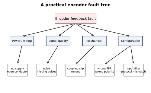
A cut-to-length conveyor produces parts that become a few millimetres shorter after several metres of travel. The raw count also loses a small amount each cycle.
What to Check
- Check wheel slip, missing pulses, and input frequency.
- Preserve drive/PLC alarm history and raw data.
- Compare the signal at encoder and receiver when relevant.
Diagnostic Sequence
- Reproduce the fault in the safest controlled condition.
- Observe raw feedback before interpreting the scaled machine value.
- Change one variable based on the strongest evidence.
- Verify the repair across repeated cycles and production speed.
Common Mistakes
- Replacing parts before the fault is reproduced.
- Changing scaling to hide a count problem.
- Stopping verification after one successful cycle.
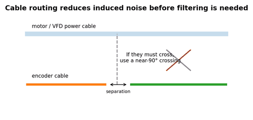
Field Rule: A temporary encoder cable routed away from the motor leads eliminates the drift. The permanent fix is corrected routing/shield bonding, not a scale change.
Case Study: Encoder Fault During Deceleration
A servo axis trips only during aggressive deceleration. Slow moves are normal.
What to Check
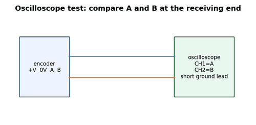
- Mark coupling hubs, trend following error, and inspect A/B or serial error status.
- Preserve drive/PLC alarm history and raw data.
- Compare the signal at encoder and receiver when relevant.
Diagnostic Sequence
- Reproduce the fault in the safest controlled condition.
- Observe raw feedback before interpreting the scaled machine value.
- Change one variable based on the strongest evidence.
- Verify the repair across repeated cycles and production speed.
Common Mistakes
- Replacing parts before the fault is reproduced.
- Changing scaling to hide a count problem.
- Stopping verification after one successful cycle.
Field Rule: Witness marks show hub slip under reverse torque. Correct coupling installation fixes the feedback error.
Case Study: New Encoder Reads Backward
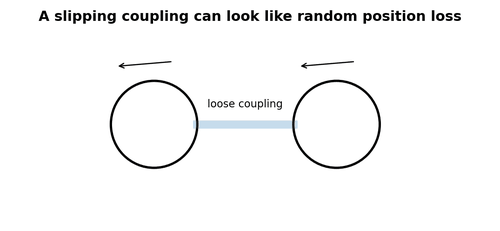
A replacement incremental encoder produces clean pulses but the PLC position decreases during positive travel.
What to Check
- Verify machine-defined positive direction and A/B phase.
- Preserve drive/PLC alarm history and raw data.
- Compare the signal at encoder and receiver when relevant.
Diagnostic Sequence
- Reproduce the fault in the safest controlled condition.
- Observe raw feedback before interpreting the scaled machine value.
- Change one variable based on the strongest evidence.
- Verify the repair across repeated cycles and production speed.
Common Mistakes
- Replacing parts before the fault is reproduced.
- Changing scaling to hide a count problem.
- Stopping verification after one successful cycle.
Field Rule: The replacement pinout swaps A and B compared with the old cable adapter. Correct pin assignment restores direction.
Case Study: 24 V Supply Present but No Pulses
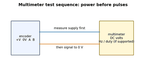
The meter shows 24 V at the cabinet power supply and the encoder is dark/dead.
What to Check
- Measure at the encoder connector under load.
- Preserve drive/PLC alarm history and raw data.
- Compare the signal at encoder and receiver when relevant.
Diagnostic Sequence
- Reproduce the fault in the safest controlled condition.
- Observe raw feedback before interpreting the scaled machine value.
- Change one variable based on the strongest evidence.
- Verify the repair across repeated cycles and production speed.
Common Mistakes
- Replacing parts before the fault is reproduced.
- Changing scaling to hide a count problem.
- Stopping verification after one successful cycle.
Field Rule: A corroded 0 V contact causes a 9 V drop. Repairing the connector restores operation.
Case Study: Works with Cable Unplugged
An open-collector channel measures correctly when disconnected but collapses when connected to the PLC.
What to Check
- Check receiver input and pull-up current.
- Preserve drive/PLC alarm history and raw data.
- Compare the signal at encoder and receiver when relevant.
Diagnostic Sequence
- Reproduce the fault in the safest controlled condition.
- Observe raw feedback before interpreting the scaled machine value.
- Change one variable based on the strongest evidence.
- Verify the repair across repeated cycles and production speed.
Common Mistakes
- Replacing parts before the fault is reproduced.
- Changing scaling to hide a count problem.
- Stopping verification after one successful cycle.
Field Rule: The signal was connected to the wrong common group, effectively loading the output. Correct wiring fixes the level.
Case Study: PLC Count Freezes at Full Speed
Encoder counts during jog but freezes near maximum rpm.
What to Check
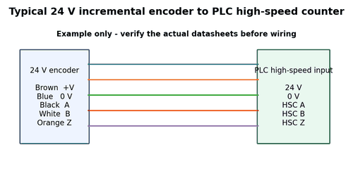
- Calculate pulse frequency and check HSC/filter limits.
- Preserve drive/PLC alarm history and raw data.
- Compare the signal at encoder and receiver when relevant.
Diagnostic Sequence
- Reproduce the fault in the safest controlled condition.
- Observe raw feedback before interpreting the scaled machine value.
- Change one variable based on the strongest evidence.
- Verify the repair across repeated cycles and production speed.
Common Mistakes
- Replacing parts before the fault is reproduced.
- Changing scaling to hide a count problem.
- Stopping verification after one successful cycle.
Field Rule: The channel was wired to a normal filtered input rather than the dedicated HSC terminal.
Case Study: Homing Fails Once Every 20 Starts
The axis finds the home sensor but occasionally reports reference not found.
What to Check
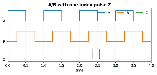
- Capture home sensor and Z over repeated cycles.
- Preserve drive/PLC alarm history and raw data.
- Compare the signal at encoder and receiver when relevant.
Diagnostic Sequence
- Reproduce the fault in the safest controlled condition.
- Observe raw feedback before interpreting the scaled machine value.
- Change one variable based on the strongest evidence.
- Verify the repair across repeated cycles and production speed.
Common Mistakes
- Replacing parts before the fault is reproduced.
- Changing scaling to hide a count problem.
- Stopping verification after one successful cycle.
Field Rule: The index pulse occurs just outside the search window because the coupling shifted. Re-aligning encoder index resolves it.
Case Study: Fault After Washdown
Feedback alarms occur the morning after sanitation.
What to Check
- Inspect connector sealing and insulation.
- Preserve drive/PLC alarm history and raw data.
- Compare the signal at encoder and receiver when relevant.
Diagnostic Sequence
- Reproduce the fault in the safest controlled condition.
- Observe raw feedback before interpreting the scaled machine value.
- Change one variable based on the strongest evidence.
- Verify the repair across repeated cycles and production speed.
Common Mistakes
- Replacing parts before the fault is reproduced.
- Changing scaling to hide a count problem.
- Stopping verification after one successful cycle.
Field Rule: Moisture inside a connector creates leakage on one differential conductor. Replacing the connector and improving drip routing fixes it.
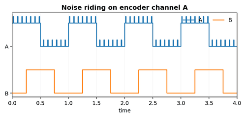
Case Study: False Counts When Brake Releases
A vertical axis gains several counts when the brake contactor opens.
What to Check
- Observe stationary raw count and scope A/B during brake switching.
- Preserve drive/PLC alarm history and raw data.
- Compare the signal at encoder and receiver when relevant.
Diagnostic Sequence
- Reproduce the fault in the safest controlled condition.
- Observe raw feedback before interpreting the scaled machine value.
- Change one variable based on the strongest evidence.
- Verify the repair across repeated cycles and production speed.
Common Mistakes
- Replacing parts before the fault is reproduced.
- Changing scaling to hide a count problem.
- Stopping verification after one successful cycle.
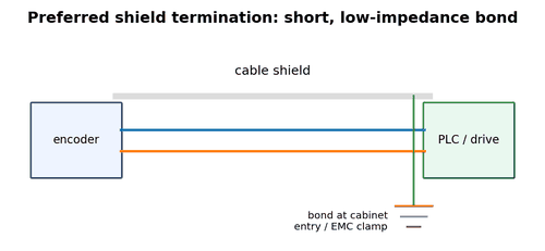
Field Rule: Poor shield termination allows the brake transient to couple into single-ended encoder lines. EMC correction eliminates false edges.
Case Study: Absolute Position Offset After Replacement
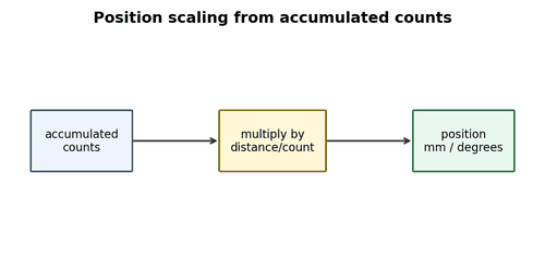
The machine starts with position shifted by 120 degrees after installing a compatible absolute encoder.
What to Check
- Compare raw value, direction, preset, and controller offset.
- Preserve drive/PLC alarm history and raw data.
- Compare the signal at encoder and receiver when relevant.
Diagnostic Sequence
- Reproduce the fault in the safest controlled condition.
- Observe raw feedback before interpreting the scaled machine value.
- Change one variable based on the strongest evidence.
- Verify the repair across repeated cycles and production speed.
Common Mistakes
- Replacing parts before the fault is reproduced.
- Changing scaling to hide a count problem.
- Stopping verification after one successful cycle.
Field Rule: The new encoder factory zero differs. Applying the documented electronic preset restores machine zero.
Case Study: Intermittent Fault at Mid-Stroke
A gantry faults near the center of travel regardless of direction.
What to Check
- Inspect drag chain and trend signal by position.
- Preserve drive/PLC alarm history and raw data.
- Compare the signal at encoder and receiver when relevant.
Diagnostic Sequence
- Reproduce the fault in the safest controlled condition.
- Observe raw feedback before interpreting the scaled machine value.
- Change one variable based on the strongest evidence.
- Verify the repair across repeated cycles and production speed.
Common Mistakes
- Replacing parts before the fault is reproduced.
- Changing scaling to hide a count problem.
- Stopping verification after one successful cycle.
Field Rule: One conductor is fractured where the cable repeatedly bends. A continuous-flex replacement fixes the fault.
Case Study: Speed Oscillates at Very Low RPM
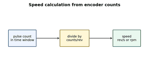
A slow-turning process shows a jumping rpm display but no physical speed change.
What to Check
- Compare raw period between pulses and software update method.
- Preserve drive/PLC alarm history and raw data.
- Compare the signal at encoder and receiver when relevant.
Diagnostic Sequence
- Reproduce the fault in the safest controlled condition.
- Observe raw feedback before interpreting the scaled machine value.
- Change one variable based on the strongest evidence.
- Verify the repair across repeated cycles and production speed.
Common Mistakes
- Replacing parts before the fault is reproduced.
- Changing scaling to hide a count problem.
- Stopping verification after one successful cycle.
Field Rule: The program uses a short count window with too few pulses. Period measurement or longer averaging stabilizes the display.
Case Study: Repeated Encoder Bearing Failures
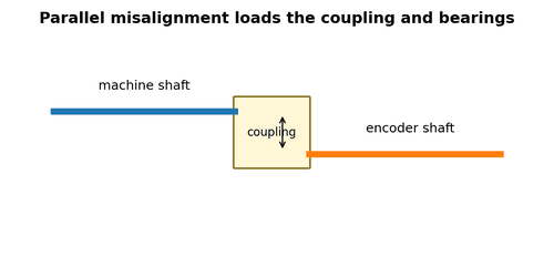
Three encoders fail within a year on the same shaft.
What to Check
- Inspect alignment, radial load, and bracket rigidity.
- Preserve drive/PLC alarm history and raw data.
- Compare the signal at encoder and receiver when relevant.
Diagnostic Sequence
- Reproduce the fault in the safest controlled condition.
- Observe raw feedback before interpreting the scaled machine value.
- Change one variable based on the strongest evidence.
- Verify the repair across repeated cycles and production speed.
Common Mistakes
- Replacing parts before the fault is reproduced.
- Changing scaling to hide a count problem.
- Stopping verification after one successful cycle.
Field Rule: A rigid coupling forces shaft misalignment into the encoder bearings. Correct alignment and coupling selection stop repeat failures.
Case Study: One Differential Wire Open
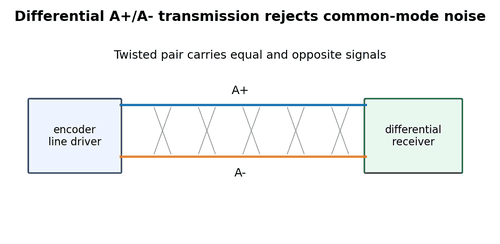
The encoder works slowly but faults near full speed and around contactor switching.
What to Check
- Measure A+ and A- individually and differentially.
- Preserve drive/PLC alarm history and raw data.
- Compare the signal at encoder and receiver when relevant.
Diagnostic Sequence
- Reproduce the fault in the safest controlled condition.
- Observe raw feedback before interpreting the scaled machine value.
- Change one variable based on the strongest evidence.
- Verify the repair across repeated cycles and production speed.
Common Mistakes
- Replacing parts before the fault is reproduced.
- Changing scaling to hide a count problem.
- Stopping verification after one successful cycle.
Field Rule: A- is open at a connector. The receiver loses differential noise rejection. Repairing the contact restores margin.
Case Study: Counts Exactly Four Times Too High
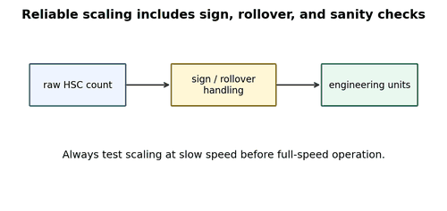
The machine travels 100 mm but software reports about 400 mm after controller replacement.
What to Check
- Check PPR versus quadrature mode.
- Preserve drive/PLC alarm history and raw data.
- Compare the signal at encoder and receiver when relevant.
Diagnostic Sequence
- Reproduce the fault in the safest controlled condition.
- Observe raw feedback before interpreting the scaled machine value.
- Change one variable based on the strongest evidence.
- Verify the repair across repeated cycles and production speed.
Common Mistakes
- Replacing parts before the fault is reproduced.
- Changing scaling to hide a count problem.
- Stopping verification after one successful cycle.
Field Rule: The new HSC counts x4 edges while old software scale already multiplied by four. Correcting one side fixes the error.
Case Study: Position Jumps at 32767
Position occasionally becomes negative at the same count.
What to Check
- Inspect integer data types.
- Preserve drive/PLC alarm history and raw data.
- Compare the signal at encoder and receiver when relevant.
Diagnostic Sequence
- Reproduce the fault in the safest controlled condition.
- Observe raw feedback before interpreting the scaled machine value.
- Change one variable based on the strongest evidence.
- Verify the repair across repeated cycles and production speed.
Common Mistakes
- Replacing parts before the fault is reproduced.
- Changing scaling to hide a count problem.
- Stopping verification after one successful cycle.
Field Rule: A 16-bit signed intermediate variable overflows. Changing calculation to a wider type resolves the apparent encoder fault.
Case Study: Serial Encoder CRC Errors
A smart encoder reports correct position most of the time but CRC error counter rises with motor load.
What to Check
- Check differential waveform, termination, route, and ground potential.
- Preserve drive/PLC alarm history and raw data.
- Compare the signal at encoder and receiver when relevant.
Diagnostic Sequence
- Reproduce the fault in the safest controlled condition.
- Observe raw feedback before interpreting the scaled machine value.
- Change one variable based on the strongest evidence.
- Verify the repair across repeated cycles and production speed.
Common Mistakes
- Replacing parts before the fault is reproduced.
- Changing scaling to hide a count problem.
- Stopping verification after one successful cycle.
Field Rule: Cable shield was not bonded at the cabinet entry. Correct EMC termination reduces errors to zero.
Case Study: Index Pulse Exists but Home Is Wrong
Z is visible on the scope and the axis homes every time, but final position is offset after maintenance.
What to Check
- Check physical encoder orientation and home offset.
- Preserve drive/PLC alarm history and raw data.
- Compare the signal at encoder and receiver when relevant.
Diagnostic Sequence
- Reproduce the fault in the safest controlled condition.
- Observe raw feedback before interpreting the scaled machine value.
- Change one variable based on the strongest evidence.
- Verify the repair across repeated cycles and production speed.
Common Mistakes
- Replacing parts before the fault is reproduced.
- Changing scaling to hide a count problem.
- Stopping verification after one successful cycle.
Field Rule: Encoder body was rotated on an adjustable mount, moving the index angle. Re-indexing the mount restores the reference.