Maintenance and automation interviews do not always end with questions across a desk.
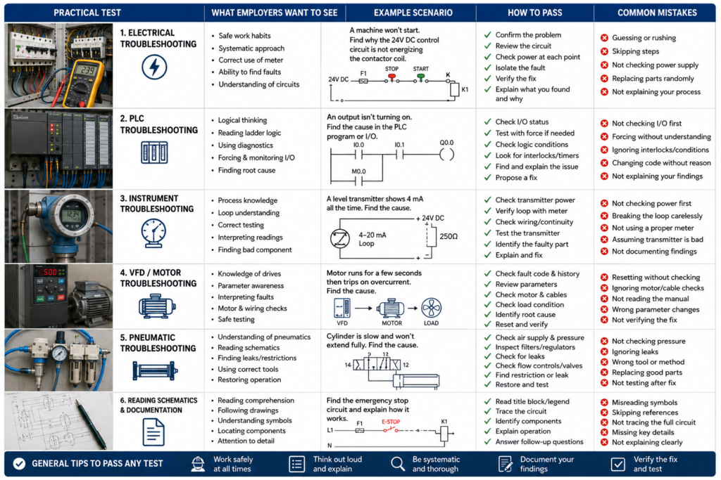
Many employers want to see how you approach a real fault. They may place a motor-control circuit, sensor, PLC trainer or damaged component in front of you and ask:
Why is it not working?
The test is usually not designed to discover whether you can memorise every fault code. It is designed to reveal how you think.
Hiring managers are watching whether you:
- Work safely
- Confirm the symptom
- Use drawings and measurements
- Test one possibility at a time
- Avoid replacing random components
- Explain your reasoning
- Know when to stop and ask for help
You do not always need to find the final fault to perform well.
A candidate who follows a safe, logical process may score better than someone who guesses correctly but cannot explain why.
What Employers Are Really Testing
A practical troubleshooting assessment normally evaluates four areas.
| Area | What the employer wants to see |
|---|---|
| Safety | You recognise hazards and isolate equipment correctly |
| Technical knowledge | You understand circuits, devices and machine behaviour |
| Diagnostic method | You test logically instead of guessing |
| Communication | You explain findings and ask useful questions |
The strongest approach is:
Make safe
→ Confirm the problem
→ Gather information
→ Divide the system
→ Measure
→ Identify the cause
→ Verify the repair
Do not begin dismantling equipment before understanding the fault.
1. The Motor-Control Circuit Test
A common test uses a contactor-controlled motor or training board.
The employer may introduce a fault such as:
- Blown control fuse
- Open stop-button contact
- Tripped overload
- Failed contactor coil
- Missing phase
- Loose terminal
- Incorrect auxiliary contact
- Low control voltage
You may be given a schematic, multimeter and limited time.
How to approach it
First establish whether the equipment can be energised safely. Ask what isolation and live-testing procedures apply.
Then separate the power and control circuits.
For the control side, trace:
Control supply
→ Fuse
→ Stop circuit
→ Start command
→ Interlocks
→ Overload contact
→ Contactor coil
If the contactor does not pull in, measure systematically along that path.
If the contactor pulls in but the motor does not run, check:
- Main supply
- Contactor power contacts
- Overload path
- Cable
- Motor terminals
- Mechanical load
Do not immediately declare the motor faulty because it is the largest component in front of you.
What makes a strong answer
Say what you expect before measuring:
I expect control voltage between these terminals when the start button is pressed. If it is missing, I will work backward toward the supply.
That demonstrates understanding rather than random meter use.
2. The Sensor and PLC Input Test
Another common setup includes a proximity sensor connected to a PLC input.
The fault may involve:
- Incorrect PNP or NPN sensor
- Broken 0 V connection
- Missing 24 V supply
- Incorrect PLC input common
- Misaligned sensor
- Wrong input address
- Damaged cable
- Sensor LED on but no valid PLC signal
How to approach it
Check the complete signal chain:
Physical target
→ Sensor operation
→ Sensor output
→ Terminal wiring
→ PLC input LED
→ PLC tag
→ Program use
A glowing sensor LED does not prove the PLC receives the signal.
Measure the sensor supply and output relative to the correct reference. Then confirm whether the corresponding PLC input channel changes.
If the physical input changes but the machine still does not respond, continue into the program.
If the input never changes, stay in the field circuit.
This separation is important. It prevents software modifications being used to hide a wiring fault.
3. Reading an Electrical Drawing
Some employers provide a schematic and ask you to locate:
- The motor protection device
- The contactor coil
- The emergency-stop circuit
- A PLC input
- A terminal number
- The supply feeding a sensor
- The output controlling a solenoid
They may also describe a symptom and ask which points you would test.
How to pass
Do not rush through the drawing.
Identify:
- Supply voltage
- Protection
- Control devices
- Output device
- Terminal references
- Cross-references
- Wire numbers
Explain the current path in plain language.
For example:
The 24 V supply passes through the stop and safety conditions, then through the overload auxiliary contact before reaching the contactor coil.
Employers are not only testing symbol recognition. They want to know whether you can use a drawing during a real breakdown.
4. The Faulty Component Table
You may receive several components and be asked to test them:
- Fuse
- Contactor coil
- Relay
- Limit switch
- Overload contact
- Solenoid valve coil
- Motor winding
- Proximity sensor
The employer may ask which are good and which are faulty.
How to approach it
Before measuring, explain what test is appropriate.
For a coil, check:
- Correct rated voltage
- Resistance
- Open circuit
- Shorted winding
- Physical damage
For a switch or contact, verify continuity in both states.
For a motor, compare winding resistances rather than relying on one measurement. Check whether insulation testing is appropriate and whether the motor is disconnected from sensitive electronics.
Do not use resistance mode on an energised circuit.
That single mistake can end the interview quickly.
5. The VFD Fault Test
A drive may show a fault, remain in local mode or refuse to start.
Common test conditions include:
- Missing run command
- Incorrect control source
- No speed reference
- Active fault
- Safe Torque Off open
- Incorrect motor data
- Local/remote mode mismatch
- Communication failure
How to approach it
Separate the drive’s conditions:
Power present?
Drive ready?
Safety enable healthy?
Run command received?
Speed reference present?
Motor connected?
Active fault?
Read the display and status words before changing parameters.
Do not perform a factory reset because you do not recognise the settings. That may erase the only working configuration.
A strong candidate checks the existing parameter state, compares it with the drawing or manual and changes only what is justified.
6. The Mechanical Troubleshooting Test
Not every practical assessment is electrical.
You may be given a conveyor, bearing assembly, pneumatic cylinder or gearbox with symptoms such as:
- Noise
- Vibration
- Overheating
- Slow movement
- Uneven wear
- Repeated belt failure
- Air leakage
Employers want to see whether you look beyond the failed part.
For a repeatedly damaged bearing, investigate:
- Alignment
- Lubrication
- Contamination
- Shaft condition
- Incorrect fitting
- Excessive load
- Vibration
- Installation force
Replacing the bearing without finding why it failed is not complete troubleshooting.
7. The “Machine Will Not Start” Scenario
Sometimes the test is entirely verbal.
The interviewer says:
The operator presses Start, but nothing happens. What do you check?
A weak answer is:
I would check the PLC.
A stronger answer separates the system:
Safety healthy?
Control power present?
PLC running?
Start command received?
Permissives satisfied?
Output commanded?
Actuator energised?
Physical movement possible?
You may also ask:
- Did the machine run earlier?
- Was maintenance recently performed?
- Are there alarms?
- Is the machine in automatic mode?
- Did the fault begin after a product jam?
- Are other devices affected?
Good questions demonstrate diagnostic maturity.
How to Behave During the Test
Explain your reasoning
Do not work silently unless specifically requested.
Say:
The contactor is not energising, so I will first confirm whether the coil receives its rated voltage.
This allows the interviewer to assess your method, even when time expires before you find the fault.
Do not guess measurements
Never pretend to have measured something you did not measure.
Say:
I have confirmed voltage at the fuse output, but I have not yet verified it at the overload contact.
Precision builds trust.
Avoid changing several things at once
If you tighten three terminals, reset the overload and change a parameter simultaneously, you may restore operation without knowing the original cause.
Make one controlled change and test again.
Use the correct instrument setting
Before measuring, verify:
- AC or DC voltage
- Current or voltage input socket
- Resistance mode
- Expected measurement range
- Reference point
Interviewers notice meter handling immediately.
Respect safety boundaries
Ask before:
- Energising equipment
- Removing guards
- Resetting safety devices
- Performing live measurements
- Disconnecting conductors
- Forcing PLC signals
- Running a motor
A practical test is not an excuse to ignore normal safety rules.
Common Mistakes That Cost Candidates the Job
Replacing parts without evidence
Saying “I would replace the PLC” before checking the input voltage suggests expensive guesswork.
Blaming software immediately
Many apparent PLC faults are caused by wiring, sensors, protection devices or mechanical conditions.
Ignoring the operator’s description
The person running the machine may know exactly what happened before the failure.
Bypassing interlocks
Never suggest bypassing an emergency stop or guard switch to “see whether it runs.”
Using only continuity tests
Continuity can be useful, but a connection may appear good without load and fail when current flows.
Voltage-drop testing may reveal faults that an unloaded resistance test misses.
Failing to verify the repair
Finding a loose wire is not the end.
Reconnect it properly, test the complete operating cycle and confirm that the fault has not created another problem.
A Strong Troubleshooting Script
When unsure how to begin, use this structure:
First, I would make the equipment safe and confirm the exact symptom. I would review alarms, drawings and recent work, then divide the system into power, control, software and mechanical sections. I would test from a known-good point, compare measurements with expected values and make one change at a time. After repairing the cause, I would test normal operation, check relevant fault conditions and document the work.
That answer fits many practical scenarios because it demonstrates the process employers want.
Final Thoughts
The practical test is not only about finding a hidden loose wire.
It shows how you behave when faced with unfamiliar equipment and limited information.
Employers want someone who can:
Work safely
+
Measure correctly
+
Think logically
+
Communicate clearly
+
Confirm the real cause
You may not recognise every component immediately. You may not know the employer’s specific PLC platform.
That is not automatically a failure.
A calm technician who admits what they do not know, checks documentation and follows a structured diagnostic process is much safer to hire than someone who guesses confidently and starts changing settings.
The best way to prepare is not memorising 100 fault answers.
Practise troubleshooting real circuits, explaining each decision and proving the cause before touching the replacement-parts shelf.