A pressure sensor is used to measure gas or liquid pressure and send that value to a PLC, controller, display, or monitoring system.
Pressure sensors are used in:
Water systems
Hydraulic systems
Pneumatic systems
Vacuum systems
Pump control
Filter monitoring
Hydrostatic level measurement
Steam systems
CIP/SIP cleaning
Compressed air systems
Food and beverage processes
Chemical systems
Machine protection
When a pressure sensor gives a wrong value, the problem is not always the sensor itself.
The fault can come from:
Wrong pressure range
Wrong pressure type
Blocked pressure port
Damaged diaphragm
Bad 24V supply
Wrong 4–20 mA scaling
Wrong PLC scaling
Wrong zero setting
Air trapped in liquid lines
Liquid trapped in gas lines
Temperature drift
Overpressure damage
Pressure spikes
Wrong sensor installation
Loose connector
Cable damage
Poor grounding
Electrical noise
Wrong absolute/gauge/differential sensor type
Clogged impulse line
Bad transmitter configuration
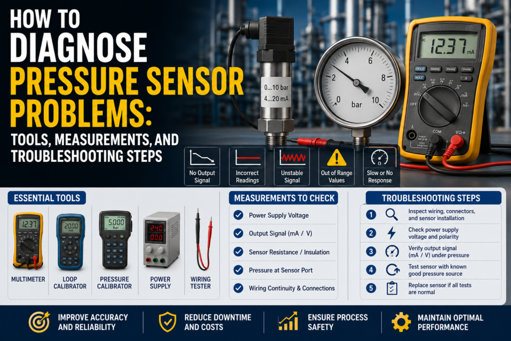
The best way to diagnose pressure sensor problems is to check the system step by step.
Important Safety Note
Pressure sensors are often installed on systems that can be dangerous.
Before troubleshooting:
Follow lockout/tagout procedures.
Depressurize the line before removing a sensor.
Check if the medium is hot, corrosive, toxic, flammable, or under high pressure.
Wear correct PPE.
Do not remove sensors from hydraulic, steam, chemical, or compressed air systems while pressurized.
Do not exceed the sensor pressure range during testing.
Do not apply an insulation tester to connected PLC inputs or transmitter electronics.
Use proper rated hoses, fittings, and test equipment.
Pressure can injure people quickly, especially in hydraulic, steam, and compressed air systems.
First: Identify the Pressure Sensor Type
Before testing, identify what type of pressure sensor you have.
The most important things to check are:
Pressure type
Pressure range
Output signal
Power supply
Process connection
Medium type
Sensor technology
PLC input type
Pressure Type: Absolute, Gauge, or Differential
This is very important.
A sensor can be electrically healthy but still give a “wrong” value if the wrong pressure type is used.
Gauge Pressure Sensor
A gauge pressure sensor measures pressure relative to atmospheric pressure.
At normal atmospheric pressure, a gauge pressure sensor should read:
0 bar gauge
or
0 psi gauge
Gauge sensors are common in:
Hydraulic systems
Pneumatic systems
Compressed air
Pump discharge pressure
Water lines
Open tank hydrostatic level
Vacuum grippers
Absolute Pressure Sensor
An absolute pressure sensor measures pressure relative to a complete vacuum.
At normal atmospheric pressure, an absolute pressure sensor should read approximately:
1.013 bar abs
or
101.3 kPa abs
or
14.7 psi abs
So if an absolute pressure sensor is open to atmosphere and shows around 1 bar, that can be correct.
Do not expect it to show zero.
Absolute pressure sensors are common in:
Vacuum systems
Autoclaves
Steam sterilization
Barometric pressure
Sealed processes
Systems where atmospheric pressure changes matter
Differential Pressure Sensor
A differential pressure sensor measures the pressure difference between two points.
It has two pressure connections:
High side
Low side
It measures:
Differential pressure = High side pressure – Low side pressure
Differential pressure sensors are used for:
Filter clogging detection
Closed tank level measurement
Flow measurement
Cleanroom pressure
Ventilation systems
Heat exchangers
If the high and low side are reversed, the reading may be negative or incorrect.
Common Pressure Sensor Fault Symptoms
Common symptoms include:
No pressure reading
Pressure stuck at zero
Pressure stuck at maximum
Reading too high
Reading too low
Reading jumps randomly
Pressure drifts over time
Sensor display correct but PLC value wrong
4–20 mA stuck at 4 mA
4–20 mA stuck at 20 mA
Output below 4 mA or above 20 mA
0–10V output stuck at 0V or 10V
Pressure switch does not switch
Pressure switch always ON
Pressure value changes with temperature
Sensor fails after pressure spikes
Vacuum value wrong
Hydrostatic level reading wrong
Differential pressure reading negative
Filter alarm activates too early or too late
Each symptom points to a different possible fault.
Tools Needed for Pressure Sensor Troubleshooting
1. Digital Multimeter
A multimeter is the first tool to use.
Use it to check:
24V DC supply
4–20 mA signal
0–10V signal
PNP output
NPN output
Relay contact
Cable continuity
Short circuits
Loose wiring
Grounding problems
A good multimeter can solve many basic pressure sensor faults.
2. Loop Calibrator / Process Meter
A loop calibrator is very useful for 4–20 mA pressure transmitters.
Use it to:
Measure loop current
Simulate 4–20 mA into the PLC
Check PLC scaling
Check HMI scaling
Check alarms
Prove if the fault is sensor-side or PLC-side
If the sensor display is correct but the PLC value is wrong, use a loop calibrator.
3. Pressure Calibrator / Hand Pump
A pressure calibrator lets you apply a known pressure to the sensor.
It can be:
Pneumatic hand pump
Hydraulic hand pump
Pressure calibrator with display
Deadweight tester
Vacuum hand pump
Use it to compare the sensor output against a known pressure.
This is one of the best ways to prove whether the sensor is accurate.
4. Reference Pressure Gauge
A reference gauge is useful for comparing real pressure.
It can be:
Digital pressure gauge
Analog pressure gauge
Calibrated test gauge
Manometer
Vacuum gauge
The reference gauge should have a suitable range and accuracy.
5. Manometer
A manometer is useful for low pressure and differential pressure.
It is commonly used for:
Ventilation systems
Filter monitoring
Cleanroom pressure
Low-pressure gas systems
Small differential pressure checks
6. Vacuum Pump / Vacuum Gauge
Useful for vacuum sensors.
Use it to test:
Negative gauge pressure
Absolute pressure
Vacuum switches
Vacuum transmitters
Pick-and-place vacuum systems
7. PLC Software
Use PLC software to check:
Raw analog input value
Scaled pressure value
Analog input configuration
Alarm logic
HMI scaling
Engineering units
Input filtering
Wrong channel assignment
Digital communication values
Many “bad pressure sensor” problems are PLC scaling problems.
8. Sensor Configuration Tool
Some pressure sensors are configurable by:
Display buttons
IO-Link
HART
USB adapter
Field communicator
Manufacturer software
Use the configuration tool to check:
Pressure range
Output range
Zero offset
Units
Damping
Switching points
PNP/NPN behavior
NO/NC setting
Alarm current
Digital mapping
Sensor diagnostics
9. Insulation Tester
Use carefully.
An insulation tester can help find:
Damaged cable insulation
Water in connector
Short to ground
Moisture in junction box
Cable leakage
But do not test connected PLC inputs, transmitters, or sensor electronics.
Disconnect first and follow the manual.
10. Oscilloscope
An oscilloscope is useful for difficult noise problems.
Use it to find:
Power supply ripple
Signal noise
Voltage spikes
VFD interference
Pressure signal oscillation
Switching noise from contactors
Not always needed, but useful when the pressure value jumps randomly.
11. Thermometer
Temperature affects pressure sensor accuracy.
Use a thermometer to check:
Process temperature
Ambient temperature
Steam temperature
Cabinet temperature
Hydraulic oil temperature
This is important if the pressure reading drifts as the system heats up.
Step 1: Check the Real Process Pressure
Before blaming the sensor, check if the process pressure is actually what you expect.
Ask:
Is the pump running?
Is the valve open?
Is the line pressurized?
Is the tank empty or full?
Is the filter blocked?
Is the system in vacuum?
Is the pressure trapped between closed valves?
Is there air in a liquid line?
Is there liquid in a gas line?
Is the sensor installed at the correct point?
A pressure sensor can only measure the pressure at its own installation point.
If the port is blocked or installed in the wrong location, the reading may not represent the real process.
Step 2: Check Local Display or Status LED
If the pressure sensor has a display, start there.
Check:
Does it power on?
Does it show pressure?
Does it show an alarm?
Does it show overrange?
Does it show underrange?
Does it show sensor fault?
Does it show the same pressure as the PLC?
Does it show correct units?
If Display Is Correct but PLC Is Wrong
The problem is likely:
4–20 mA wiring
0–10V wiring
PLC analog input
PLC scaling
HMI scaling
Wrong units
Wrong channel
Digital communication mapping
If Display Is Wrong Too
The problem may be:
Pressure port blockage
Wrong sensor range
Wrong pressure type
Bad zero setting
Sensor damage
Process problem
Power supply problem
Configuration problem
Step 3: Check Power Supply Voltage
Most industrial pressure sensors use 24V DC.
Measure voltage at the sensor terminals.
Good 24V DC Reading
For many industrial sensors:
20.4V DC to 28.8V DC
This is 24V ±20%.
Always check the sensor datasheet.
Bad Readings
0V
Wrong polarity
Voltage below allowed range
Unstable voltage
Voltage drops under load
High AC ripple
Loose 0V/common wire
Overloaded power supply
Measure power while the sensor is connected and working.
A supply can look normal with no load but fail under load.
Step 4: Check 4–20 mA Output
Many pressure transmitters use 4–20 mA.
Example range:
0–10 bar = 4–20 mA
| Pressure | Expected Current |
|---|---|
| 0 bar | 4 mA |
| 2.5 bar | 8 mA |
| 5 bar | 12 mA |
| 7.5 bar | 16 mA |
| 10 bar | 20 mA |
Good 4–20 mA Measurements
Around 4 mA at lower range value
Around 12 mA at 50% of range
Around 20 mA at upper range value
Signal changes smoothly with pressure
Measured current matches sensor display and configured range
Bad 4–20 mA Measurements
| Reading | Possible Problem |
|---|---|
| 0 mA | No power, broken loop, wrong wiring |
| Below 3.6 mA | Fault alarm on many transmitters |
| 4 mA all the time | Zero pressure, output stuck, wrong range, blocked port |
| 20 mA all the time | Full scale, overpressure, saturated output, wrong range |
| Above 21 mA | Fault alarm or overrange on many transmitters |
| Jumping current | Noise, loose wire, unstable process |
| Display correct but mA wrong | Output configuration fault |
| mA correct but PLC wrong | PLC scaling fault |
Alarm current values depend on transmitter configuration.
Step 5: Check 0–10V Output
Some pressure sensors use voltage output.
Example range:
0–10 bar = 0–10V
| Pressure | Expected Voltage |
|---|---|
| 0 bar | 0V |
| 2.5 bar | 2.5V |
| 5 bar | 5V |
| 7.5 bar | 7.5V |
| 10 bar | 10V |
Good 0–10V Measurements
0V at lower range value
5V at 50% of range
10V at upper range value
Voltage changes smoothly with pressure
PLC value matches measured voltage
Bad 0–10V Measurements
0V all the time
10V all the time
Voltage unstable
Voltage drops when connected to PLC
Correct voltage but wrong PLC value
Signal affected by motor or VFD operation
Long cable causing voltage drop or noise
Voltage outputs are usually more sensitive to noise and cable length than 4–20 mA outputs.
Step 6: Check Pressure Switch Output
Some pressure sensors act as pressure switches.
They may have:
PNP output
NPN output
Relay output
IO-Link switching output
PNP Pressure Switch
A PNP output switches positive voltage to the PLC input.
Good PNP Measurements
Output OFF: usually near 0V or floating
Output ON: near +24V DC
PLC input turns ON when output is ON
Sensor LED matches PLC input
Bad PNP Measurements
Output never reaches +24V
Output stuck at +24V
Output LED ON but PLC input OFF
Wrong PLC input common
Broken output wire
Output overloaded or shorted
NPN Pressure Switch
An NPN output pulls the PLC input to 0V.
Good NPN Measurements
Output ON: near 0V DC
PLC input turns ON with correct wiring
Correct input type used
Bad NPN Measurements
Sensor wired to PNP input by mistake
Output does not pull low
Output stuck at 0V
No pull-up path
Wrong common wiring
PNP/NPN mismatch is a very common fault.
Relay Pressure Switch
Relay output sensors have dry contacts.
Good Relay Measurements
NO contact inactive: open circuit
NO contact active: closed circuit
NC contact inactive: closed circuit
NC contact active: open circuit
A closed relay contact should usually be below 1 Ω plus test lead resistance.
Bad Relay Measurements
Contact always open
Contact always closed
High resistance when closed
Wrong NO/NC terminal used
Relay overloaded
Switch point configured wrong
Step 7: Simulate the PLC Input
If the sensor output is correct but the PLC value is wrong, simulate the PLC input.
For 4–20 mA:
| Simulated Current | PLC Should Show |
|---|---|
| 4 mA | 0% of range |
| 8 mA | 25% of range |
| 12 mA | 50% of range |
| 16 mA | 75% of range |
| 20 mA | 100% of range |
For 0–10V:
| Simulated Voltage | PLC Should Show |
|---|---|
| 0V | 0% of range |
| 2.5V | 25% of range |
| 5V | 50% of range |
| 7.5V | 75% of range |
| 10V | 100% of range |
If the PLC does not show the correct value, the problem is probably:
PLC scaling
Analog input setting
Wrong signal type
Wrong input channel
Wrong engineering range
Wrong HMI tag
Wrong units
Step 8: Check PLC Scaling and Units
Pressure scaling mistakes are common.
Check:
Sensor range
PLC range
HMI range
bar vs kPa vs psi
gauge vs absolute pressure
4–20 mA vs 0–20 mA
0–10V vs 2–10V
Decimal point
Offset
Wrong channel
Wrong analog input type
Example
Sensor range:
0–10 bar = 4–20 mA
Measured current:
12 mA
Correct pressure:
5 bar
If the PLC shows 7.5 bar, the pressure sensor may be fine. The PLC scaling may be wrong.
Step 9: Check Pressure Range
A pressure sensor must match the real process pressure.
Good Range Selection
Normal working pressure is inside the measuring range
Pressure peaks are below overpressure limit
Sensor has enough resolution for the application
Sensor is not constantly near maximum range
Sensor is not too large for low-pressure measurement
Bad Range Selection
0–100 bar sensor used for 0–1 bar process
0–6 bar sensor exposed to 20 bar pressure spike
Vacuum process using pressure-only sensor
Gauge sensor used where absolute pressure is needed
Differential pressure sensor range too small
Overpressure limit exceeded
If the sensor range is too large, accuracy and resolution may be poor.
If the range is too small, the sensor may saturate or get damaged.
Step 10: Check Zero Pressure Reading
Zero depends on the pressure type.
Gauge Sensor at Atmosphere
A gauge pressure sensor open to atmosphere should read approximately:
0 bar gauge
Absolute Sensor at Atmosphere
An absolute pressure sensor open to atmosphere should read approximately:
1.013 bar abs
or
101.3 kPa abs
Differential Sensor With Both Ports Open
A differential pressure sensor with both ports open to the same pressure should read:
0 differential pressure
Bad Zero Readings
Gauge sensor shows pressure when open to atmosphere
Absolute sensor shows 0 bar at atmosphere
Differential sensor shows offset with both ports equal
Zero changes after pressure spike
Zero drifts with temperature
Zero changes when cable is moved
Bad zero can indicate:
Wrong pressure type
Wrong zero offset
Sensor damage
Blocked vent
Blocked reference port
Temperature drift
Overpressure damage
Step 11: Check for Blocked Pressure Port
A blocked pressure port is a very common problem.
This can happen with:
Sludge
Product buildup
Paint
Glue
Food product
Crystallized chemical
Limescale
Rust
Oil contamination
Frozen water
Dust
Process deposits
Good
Pressure port is clean
Diaphragm is not coated
Pressure reaches the sensor quickly
Reading changes when process pressure changes
No delay or sticking
Bad
Pressure reading changes slowly
Pressure stays high after process is depressurized
Pressure stays low even when line is pressurized
Sensor only works after cleaning
Flush diaphragm covered by product
Small pressure hole blocked
Impulse line blocked
If the port is blocked, the sensor may be good but isolated from the real process pressure.
Step 12: Check the Diaphragm
The diaphragm is the sensitive mechanical part of the sensor.
Check for:
Dents
Scratches
Corrosion
Coating
Cracks
Mechanical damage
Chemical attack
Product buildup
Seal damage
Good Diaphragm
Clean
Flat or normal shape
No dents
No corrosion
No leakage
No heavy coating
Responds quickly to pressure changes
Bad Diaphragm
Dented from tool damage
Damaged by overpressure
Coated with hard product
Corroded
Leaking filling fluid
Cracked ceramic cell
Blocked flush diaphragm
Permanent zero shift after mechanical impact
Never clean a diaphragm with sharp tools.
A damaged diaphragm can permanently ruin the sensor accuracy.
Step 13: Check Cable and Connector
Cable problems are common in industrial environments.
Check:
Loose connector
Water inside connector
Corrosion
Broken cable
Crushed cable
Damaged insulation
Oil or chemical damage
Loose terminals
Broken shield
Wrong cable wiring
Good
Connector dry
Cable intact
Terminals tight
No corrosion
Signal stable when cable is moved
Shield connected correctly
Bad
Reading jumps when cable is touched
Water in connector
Green corrosion
Intermittent signal
Broken conductor
Short to ground
Cable pulled tight
Damaged gland
Move the cable gently while watching the pressure value.
If the reading jumps, suspect cable or connector damage.
Step 14: Check Insulation Resistance
Insulation faults can cause unstable signals, drift, or false readings.
Disconnect sensor electronics before testing.
General Practical Values
| Insulation Resistance | Meaning |
|---|---|
| >100 MΩ | Very good |
| 20–100 MΩ | Usually acceptable, check manual |
| 1–20 MΩ | Suspicious |
| <1 MΩ | Usually bad |
Low insulation may be caused by:
Moisture in connector
Damaged cable
Chemical ingress
Water in junction box
Cracked sensor housing
Condensation
Poor cable gland
Do not insulation-test live electronics unless the manufacturer allows it.
Step 15: Check Grounding and Shielding
Pressure signals can be affected by electrical noise.
Common noise sources:
VFD motor cables
Servo drives
Large contactors
Solenoid valves
Welding equipment
Bad grounding
Long analog cables
Unshielded signal cables
Poor 24V power supply
Good
Signal cable separated from power cables
Shield connected according to manual
Ground difference close to 0V
Pressure signal stable
No pressure spikes when motors start
Bad
Pressure value jumps when VFD starts
Pressure changes with motor speed
Analog output noisy
Cable routed with motor cable
Shield disconnected
Ground difference above about 1V AC or DC
Signal spikes when contactors switch
Measure voltage between sensor body, machine frame, and panel PE.
Ideally, it should be close to 0V.
Step 16: Check Pressure With a Reference Gauge
To prove the sensor accuracy, compare it with a reference gauge.
Good
Sensor value close to reference gauge
Reading stable
Output changes smoothly
Zero returns after pressure is removed
Same result when pressure is applied again
Bad
Sensor far from reference
Sensor unstable
Pressure value sticks
Zero does not return
Reading depends on whether pressure is rising or falling
Sensor shows large offset
Use a reference gauge with suitable accuracy.
A cheap gauge may not be accurate enough to judge a precise pressure transmitter.
Step 17: Apply Known Pressure With a Pressure Calibrator
This is one of the best diagnostic tests.
Example sensor:
0–10 bar = 4–20 mA
Apply known pressures and check output.
| Applied Pressure | Expected Current |
|---|---|
| 0 bar | 4 mA |
| 2.5 bar | 8 mA |
| 5 bar | 12 mA |
| 7.5 bar | 16 mA |
| 10 bar | 20 mA |
Good
Output matches applied pressure
Signal is linear
Zero is correct
Span is correct
Reading is repeatable
Bad
Output offset at zero
Output span wrong
Reading nonlinear
Output sticks
Output noisy
Zero does not return
Sensor fails at high pressure
This test separates real sensor error from process problems.
Step 18: Check Hydrostatic Level Pressure
Pressure sensors are often used for tank level.
The formula is:
p = ρ × g × h
For water:
1 meter water column ≈ 9.81 kPa
or
1 meter water column ≈ 0.098 bar
Example
Tank has 2 meters of water.
Expected pressure at the bottom:
2 × 9.81 kPa = 19.62 kPa
That is approximately:
0.196 bar
If the sensor range is:
0–2 m water = 4–20 mA
Then:
0 m = 4 mA
1 m = 12 mA
2 m = 20 mA
Good
Pressure matches liquid height
Density setting is correct
Sensor installed at correct height
Vent tube clear for gauge sensors
PLC scaling matches tank height
Bad
Pressure does not match level
Density wrong
Sensor installed above tank bottom but not compensated
Vent tube blocked
Impulse line blocked
Closed tank pressure not compensated
PLC uses wrong tank height
Hydrostatic level errors are often caused by density, installation height, or blocked venting.
Step 19: Check Differential Pressure
For differential pressure sensors, check both pressure ports.
Common markings:
High side: H, +, HP
Low side: L, -, LP
Good
High and low side connected correctly
Both impulse lines clear
Zero reads correctly when both sides are equal
Differential pressure increases as expected
Filter pressure drop matches process condition
Bad
High and low ports reversed
One impulse line blocked
Condensation in one line
Air trapped in liquid impulse line
Liquid trapped in gas impulse line
Zero offset with equal pressure
Negative reading when positive expected
Filter Example
Pressure before filter:
3.0 bar
Pressure after filter:
2.6 bar
Differential pressure:
0.4 bar
If the sensor shows 0 bar, one line may be blocked or connected incorrectly.
If it shows negative pressure, high and low ports may be reversed.
Step 20: Check Vacuum Measurement
Vacuum can be confusing because it may be measured as gauge pressure or absolute pressure.
Gauge Vacuum
Gauge vacuum is often shown as negative pressure.
Example:
0 bar gauge = atmosphere
-0.5 bar gauge = partial vacuum
-1 bar gauge = near full vacuum
Absolute Vacuum
Absolute pressure decreases as vacuum increases.
Example:
1.013 bar abs = atmosphere
0.5 bar abs = partial vacuum
0 bar abs = perfect vacuum
Good
Sensor type matches vacuum measurement method
Vacuum pump creates expected pressure
Reading changes smoothly
Sensor range includes vacuum
PLC scaling matches gauge or absolute units
Bad
Absolute sensor expected to show negative pressure
Gauge sensor expected to show absolute pressure
Wrong scaling direction
Vacuum line leaking
Sensor range does not include vacuum
Blocked pressure connection
Always confirm whether the value is gauge or absolute.
Step 21: Check Temperature Effects
Temperature can affect pressure sensor readings.
Check:
Process temperature
Ambient temperature
Steam cleaning temperature
Cabinet temperature
Hydraulic oil temperature
Sensor temperature rating
Compensated temperature range
Good
Pressure remains stable with temperature changes
Sensor is used inside its temperature limits
Error remains within specification
No sudden drift during heating
Cable and seals rated for temperature
Bad
Pressure drifts as system warms up
Zero shifts after steam cleaning
Sensor fails after SIP/CIP cycle
Electronics too close to hot process
Medium temperature exceeds sensor limit
Seal material not suitable
Condensation enters connector after temperature cycling
If pressure reading changes with temperature while real pressure is stable, check temperature compensation and sensor suitability.
Step 22: Check Pressure Spikes and Overpressure Damage
Pressure spikes can damage sensors.
Common sources:
Pump start/stop
Water hammer
Hydraulic valve switching
Fast solenoid valves
Blocked discharge
Compressor pulses
Cleaning cycles
Steam shocks
Signs of Overpressure Damage
Permanent zero offset
Sensor stuck at high value
Sensor no longer returns to zero
Output saturated
Diaphragm damaged
Sensor works at low pressure but fails at high pressure
Calibration fails
Reading not repeatable
If pressure spikes are suspected, use:
Snubber
Damping element
Pressure restrictor
Higher pressure range
Sensor with better overpressure rating
Better valve control
Soft start logic
Step 23: Check Damping and Response Time
Many pressure sensors allow damping or filtering.
Damping smooths the signal but slows the response.
Good
Signal stable
Response fast enough for process
No false alarms
No missed pressure peaks if peaks matter
Bad
Damping too high: pressure changes appear too late
Damping too low: pressure value jumps too much
PLC filter too strong
HMI display hides fast pressure spikes
Sensor too slow for machine protection
For pump control, some damping may help.
For safety or pressure spike detection, too much damping can be dangerous.
Step 24: Check Digital Communication
Smart pressure sensors may use:
IO-Link
HART
Modbus
PROFINET
EtherNet/IP
Common problems include:
Wrong address
Wrong process data mapping
Wrong units
Wrong scaling factor
PLC reading temperature instead of pressure
Wrong byte order
Wrong parameter set
Sensor replaced but not configured
Communication timeout
If local sensor display is correct but PLC digital value is wrong, check mapping and configuration.
Troubleshooting by Symptom
1. No Pressure Reading
Possible causes:
No power
Broken cable
Wrong wiring
Broken loop
Sensor failure
PLC input fault
Wrong communication setup
Checks:
Measure 24V supply
Measure 4–20 mA or voltage output
Check cable continuity
Check sensor display
Check PLC input
Check communication status
2. Reading Stuck at Zero
Possible causes:
No pressure
Blocked pressure port
Wrong range
Gauge sensor open to atmosphere
Output stuck at 4 mA
PLC scaling wrong
Sensor damaged
Checks:
Apply known pressure
Check output mA
Check pressure port
Check sensor range
Compare display with PLC
Check zero setting
3. Reading Stuck at Maximum
Possible causes:
Overpressure
Wrong range
Blocked port holding trapped pressure
Output stuck at 20 mA
PLC scaling wrong
Sensor saturated
Diaphragm damage
Checks:
Depressurize safely
Measure output
Check local display
Apply known pressure
Inspect diaphragm
Check range setting
4. Reading Too High
Possible causes:
Wrong zero
Wrong pressure type
Blocked port with trapped pressure
PLC scaling error
Sensor offset
Temperature drift
Gauge/absolute confusion
Hydrostatic density setting wrong
Checks:
Open gauge sensor to atmosphere
Check absolute pressure expectation
Measure 4–20 mA
Simulate PLC input
Compare with reference gauge
Check zero offset
5. Reading Too Low
Possible causes:
Blocked pressure port
Pressure not reaching sensor
Leak in pressure line
Wrong range
Wrong PLC scaling
Air in liquid line
Sensor installed too high for level measurement
Diaphragm damage
Checks:
Compare with reference gauge
Check pressure port
Check impulse line
Apply known pressure
Check scaling
Check installation height
6. Reading Jumps Randomly
Possible causes:
Loose connector
Electrical noise
Pressure pulsation
VFD interference
Bad grounding
Air bubbles
Pump vibration
Sensor range too small
Cable damage
Checks:
Move cable gently
Check grounding and shield
Watch signal when pump starts
Use oscilloscope if needed
Check process pulsation
Add damping only after checking real faults
7. PLC Value Wrong but Sensor Display Correct
Possible causes:
Wrong analog scaling
Wrong units
Wrong HMI tag
Wrong input type
Wrong 4–20 mA range
Wrong digital mapping
Checks:
Measure output current or voltage
Simulate PLC input
Check PLC raw value
Check HMI scaling
Check units and range
8. Pressure Switch Does Not Switch
Possible causes:
Wrong setpoint
Wrong hysteresis
Wrong NO/NC mode
Wrong PNP/NPN wiring
Pressure never reaches setpoint
Blocked port
Sensor output damaged
Checks:
Apply known pressure
Watch output LED
Measure output voltage
Check setpoint and hysteresis
Check PLC input
Check port blockage
Quick Measurement Table
| Test | Good Measurement | Bad Measurement |
|---|---|---|
| 24V DC supply | Usually 20.4–28.8V DC | Missing, low, unstable, reversed |
| Gauge sensor at atmosphere | Around 0 bar gauge | Large offset |
| Absolute sensor at atmosphere | Around 1.013 bar abs | 0 bar abs or wrong value |
| Differential sensor equal pressure | Around 0 differential | Offset or negative unexpected |
| 4–20 mA at 0% | Around 4 mA | 0 mA, alarm current |
| 4–20 mA at 50% | Around 12 mA | Wrong current for range |
| 4–20 mA at 100% | Around 20 mA | Saturated or wrong scaling |
| 0–10V at 50% | Around 5V | Wrong voltage or unstable |
| PNP output ON | Near +24V DC | Low voltage or no change |
| NPN output ON | Near 0V DC | Does not pull low |
| Relay closed | Usually <1 Ω plus leads | High resistance or open |
| Water column pressure | 1 m ≈ 9.81 kPa | Does not match liquid height |
| Insulation resistance | >100 MΩ very good | <1 MΩ usually bad |
| Ground difference | Close to 0V | >1V suspicious |
| PLC simulation | Correct scaled value | Scaling/input problem |
What Measurements Are Usually Good?
These are general practical values:
24V DC supply around 20.4–28.8V DC
Gauge sensor open to atmosphere reads about 0 bar gauge
Absolute sensor open to atmosphere reads about 1.013 bar abs
Differential sensor with equal pressure on both ports reads about 0 differential pressure
4 mA at lower pressure range
12 mA at middle of pressure range
20 mA at upper pressure range
0–10V output gives 5V at 50% range
PNP output ON close to +24V DC
NPN output ON close to 0V DC
Relay closed contact below about 1 Ω plus lead resistance
1 meter water column equals about 9.81 kPa or 0.098 bar
Insulation resistance above 100 MΩ is very good
Ground voltage difference close to 0V
Sensor reading close to reference gauge
PLC value matches measured mA or voltage after scaling
What Measurements Are Usually Bad?
These readings usually indicate a fault:
0V supply
Wrong polarity
24V supply below allowed range
4–20 mA output at 0 mA
Output below 3.6 mA or above 21 mA without known reason
4 mA all the time while pressure changes
20 mA all the time during normal pressure
0–10V output stuck at 0V or 10V
Gauge sensor showing large pressure when open to atmosphere
Absolute sensor showing zero at atmosphere
Differential sensor offset with equal pressure
Pressure reading far from reference gauge
Sensor does not return to zero after pressure is removed
Pressure port blocked
Diaphragm damaged or dented
Insulation resistance below 1 MΩ
Pressure value jumps when cable is touched
Pressure value changes when VFD starts
PLC value does not match measured output signal
Practical Diagnostic Order
When diagnosing a pressure sensor, I would follow this order:
- Identify pressure type: gauge, absolute, or differential.
- Check sensor range and output type.
- Check the real process condition.
- Check local display and diagnostic messages.
- Measure 24V power supply.
- Measure 4–20 mA, 0–10V, PNP/NPN, or relay output.
- Compare sensor display with PLC/HMI value.
- Simulate PLC input to prove scaling.
- Check PLC units and engineering range.
- Check zero pressure reading.
- Inspect pressure port and diaphragm.
- Check cable, connector, and terminals.
- Check insulation resistance if allowed.
- Check grounding and shielding.
- Compare with a reference gauge.
- Apply known pressure using a calibrator.
- For hydrostatic level, check pressure vs liquid height.
- For differential pressure, check high/low side and impulse lines.
- For vacuum, check gauge vs absolute scaling.
- Check temperature effects, pressure spikes, and damping.
- Check digital communication mapping if used.
This order helps avoid replacing a good sensor when the real problem is wiring, scaling, blocked pressure, or wrong configuration.
Final Thoughts
Pressure sensor troubleshooting is both an electrical and mechanical task.
A pressure sensor may be electrically healthy but still show a wrong value because the pressure port is blocked, the diaphragm is damaged, the PLC scaling is wrong, the pressure type is misunderstood, or the sensor is installed in the wrong place.
The most useful tools are:
Digital multimeter
Loop calibrator
Pressure calibrator
Hand pump
Reference pressure gauge
Vacuum pump
Manometer
PLC software
Sensor configuration tool
Insulation tester
Oscilloscope
Thermometer
The most important measurements are:
24V DC supply
4–20 mA output
0–10V output
PNP/NPN/relay output
Zero pressure reading
Reference pressure comparison
Known pressure calibration test
Insulation resistance
Ground voltage difference
PLC raw and scaled values
The key rule is simple:
If the sensor display is correct but the PLC value is wrong, check wiring and scaling.
If the output signal is correct but the process value seems wrong, check pressure type, units, and PLC logic.
If the sensor itself reads wrong against a known pressure, check zero, diaphragm condition, blocked ports, overpressure damage, and calibration.