Pressure measurement is one of the most important measurements in industrial automation.
A pressure sensor measures the pressure of a gas or liquid and converts it into an electrical signal. This signal can then be used by a PLC, controller, display, or monitoring system.
Pressure sensors are used in:
Water systems
Hydraulic systems
Pneumatic systems
Food and beverage production
Chemical processing
Steam systems
CIP and SIP cleaning
Vacuum systems
Pump control
Filter monitoring
Hydrostatic level measurement
Compressed air systems
Machine safety and protection
Process control
In simple words:
A pressure sensor tells the control system how much force a gas or liquid is applying to a surface.
That value can then be used to control pumps, valves, alarms, machine processes, and safety limits.
What Is a Pressure Sensor?
A pressure sensor is a device that converts mechanical pressure into an electrical signal.
The pressure can come from:
Liquid
Gas
Steam
Oil
Air
Water
Hydraulic fluid
Process media
The electrical output can be:
4–20 mA
0–10V
0–5V
Relay output
Switching output
IO-Link
HART
Modbus
Digital fieldbus signal
In industrial automation, the most common signal is often 4–20 mA, because it works well over long cable distances and is resistant to electrical noise.
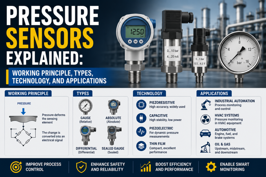
How Does a Pressure Sensor Work?
Most pressure sensors work by using a measuring diaphragm.
A diaphragm is a thin membrane inside the sensor.
When pressure is applied, the diaphragm bends slightly.
The sensor electronics detect this deformation and convert it into an electrical signal.
The basic process is:
Pressure acts on the diaphragm.
The diaphragm deforms.
The sensing element detects the deformation.
The electronics amplify and process the signal.
The transmitter outputs a usable signal to the PLC or controller.
So the key idea is:
Pressure creates mechanical deformation, and the sensor converts that deformation into an electrical value.
Main Parts of a Pressure Sensor
A typical industrial pressure sensor contains several important parts.
1. Process Connection
This is the mechanical connection between the sensor and the pipe, tank, machine, or process.
Common process connections include:
Threaded connection
Clamp connection
Flange connection
Hygienic connection
Flush diaphragm connection
Pressure port
Manifold connection
The process connection must match the pressure range, medium, temperature, and industry requirement.
2. Pressure Opening or Diaphragm
The pressure enters the sensor through a pressure port or acts directly on a diaphragm.
In many hygienic and food applications, a flush diaphragm is used so that product cannot collect inside a small pressure hole.
3. Measuring Diaphragm
The diaphragm deforms when pressure changes.
This deformation is very small, but it is enough for the sensor element to detect.
4. Sensor Element
The sensor element converts diaphragm movement or stress into an electrical signal.
Common sensor principles include:
Piezoresistive
Resistive
Capacitive
Piezoelectric
Inductive
Hall effect
MEMS
5. Signal Processing Electronics
The raw sensor signal is usually very small.
The electronics amplify, filter, linearize, and compensate the signal.
They may also correct for temperature effects.
6. Output Stage
The output stage sends the pressure value to another device.
Common outputs include:
4–20 mA
0–10V
Switching output
Digital communication
Local display
7. Housing and Electrical Connection
The housing protects the electronics.
The electrical connection can be:
M12 connector
Cable outlet
Terminal head
DIN connector
Plug connector
Fieldbus connector
The correct connection depends on the environment and installation.
Main Pressure Sensor Types by Measuring Principle
There are several technologies used to measure pressure.
The most common are:
Resistive pressure sensors
Piezoresistive pressure sensors
Capacitive pressure sensors
Piezoelectric pressure sensors
Inductive pressure sensors
Hall effect pressure sensors
MEMS pressure sensors
1. Resistive Pressure Sensors
A resistive pressure sensor measures pressure by detecting a change in electrical resistance.
When pressure causes mechanical stress in a diaphragm or measuring element, the resistance changes.
The electronics measure this resistance change and convert it into pressure.
Many resistive pressure sensors use a Wheatstone bridge circuit.
This allows small resistance changes to be measured accurately.
Simple Explanation
Pressure bends the diaphragm.
The diaphragm movement creates mechanical strain.
The strain changes resistance.
The electronics measure this resistance change.
The sensor outputs a pressure value.
2. Piezoresistive Pressure Sensors
A piezoresistive pressure sensor is a very common pressure sensor type.
It uses a semiconductor material, often silicon.
When mechanical stress is applied to the silicon sensing element, its electrical resistance changes.
This resistance change is measured and converted into pressure.
Piezoresistive sensors are widely used because they can offer:
Good accuracy
Good sensitivity
Small measuring ranges
Good long-term stability
Compact design
Good performance in process and machine applications
How Piezoresistive Pressure Sensors Work
The pressure acts on a diaphragm.
This pressure is transferred to a silicon chip or sensing element.
The silicon element changes resistance when stressed.
The resistance change is measured using a bridge circuit.
The electronics convert the bridge signal into a pressure output.
Oil-Filled Piezoresistive Sensors
In many industrial designs, the sensitive silicon chip is separated from the process medium by a stainless steel diaphragm.
Behind the diaphragm, there may be a transmission fluid such as silicone oil or another suitable filling fluid.
The process pressure acts on the metal diaphragm.
The diaphragm transfers pressure through the internal fluid to the silicon sensor chip.
This protects the sensitive chip from the process medium.
This design is common in many industrial and hygienic pressure transmitters.
3. Capacitive Pressure Sensors
A capacitive pressure sensor measures pressure by detecting a change in capacitance.
Inside the sensor, a diaphragm acts as one plate of a capacitor.
When pressure bends the diaphragm, the distance between capacitor plates changes.
This changes the capacitance.
The electronics measure this capacitance change and convert it into pressure.
Simple Explanation
Pressure moves the diaphragm.
The distance inside the capacitor changes.
Capacitance changes.
Electronics convert the change into pressure.
Capacitive pressure sensors can be very sensitive and are often used in low-pressure and differential pressure applications.
4. Piezoelectric Pressure Sensors
A piezoelectric pressure sensor uses a material that creates electrical charge when mechanical pressure is applied.
This is called the piezoelectric effect.
Piezoelectric sensors are especially useful for dynamic pressure measurement.
They are often used where pressure changes quickly.
Examples include:
Engine pressure
Combustion pressure
Vibration-related pressure
Fast pressure pulses
Dynamic machine monitoring
They are not always the best choice for slow static pressure measurement because the charge signal can decay over time.
5. Inductive Pressure Sensors
Inductive pressure sensors detect pressure by measuring changes in inductance.
Pressure moves a diaphragm, magnetic core, or mechanical element.
This changes the inductance of a coil.
The electronics detect this change and convert it into a pressure value.
Inductive sensors are less common than piezoresistive and capacitive sensors, but they can be useful in some industrial designs.
6. Hall Effect Pressure Sensors
A Hall effect pressure sensor uses a magnetic field and a Hall element.
Pressure movement changes the position of a magnet or magnetic element.
The Hall element detects this change.
The electronics convert it into pressure.
These sensors are often used in compact electromechanical pressure sensing systems.
7. MEMS Pressure Sensors
MEMS means Micro-Electro-Mechanical System.
A MEMS pressure sensor uses tiny mechanical structures built on a silicon chip.
These structures deform under pressure.
The chip converts this deformation into an electrical signal.
MEMS pressure sensors are common in:
Automotive systems
Medical devices
Consumer electronics
HVAC
Portable instruments
Industrial transmitters
Absolute pressure measurement
They are small, sensitive, and cost-effective.
Pressure Types: Absolute, Relative, and Differential Pressure
Before selecting or troubleshooting a pressure sensor, you must know what type of pressure is being measured.
The three most important pressure types are:
Absolute pressure
Relative pressure
Differential pressure
Absolute Pressure
Absolute pressure is measured relative to a complete vacuum.
A complete vacuum is zero absolute pressure.
Absolute pressure is always positive.
It is often shown as:
Pa abs
bar abs
psi abs
An absolute pressure sensor uses a sealed vacuum reference inside the sensor.
Simple Explanation
Absolute pressure compares the process pressure to vacuum.
So:
0 bar abs = perfect vacuum
1 bar abs = roughly atmospheric pressure at sea level
2 bar abs = about 1 bar above atmosphere
Typical Applications for Absolute Pressure
Absolute pressure sensors are used for:
Vacuum measurement
Vacuum pumps
Autoclaves
Sterilization systems
Steam pressure monitoring
CIP/SIP cleaning
Barometric pressure
Sealed systems
Process control where atmospheric pressure changes matter
Absolute pressure is important when the process depends on real physical pressure, not just pressure above atmosphere.
Relative Pressure / Gauge Pressure
Relative pressure, also called gauge pressure, is measured relative to the surrounding atmospheric pressure.
It can be positive or negative.
It is often shown as:
bar gauge
bar g
psi gauge
Pa gauge
A relative pressure sensor usually has a vent or reference path to atmosphere.
Simple Explanation
Gauge pressure compares process pressure to the air pressure around the sensor.
So:
0 bar gauge = same as atmospheric pressure
1 bar gauge = 1 bar above atmospheric pressure
-0.5 bar gauge = vacuum relative to atmosphere
This is the most common pressure measurement in many industrial systems.
Typical Applications for Relative Pressure
Relative pressure sensors are used for:
Hydraulic systems
Pneumatic systems
Compressed air
Pump pressure
Water pressure
Hydrostatic level in open tanks
Vacuum gripping systems
Machine pressure monitoring
Filter pressure monitoring
Process lines open to atmosphere
Differential Pressure
Differential pressure is the pressure difference between two points.
It can be positive or negative.
The sensor has two pressure connections:
High pressure side
Low pressure side
The sensor measures:
Differential pressure = pressure 1 – pressure 2
Simple Explanation
Differential pressure does not measure pressure compared to air or vacuum.
It measures the difference between two pressures.
For example:
Pressure before filter = 3.0 bar
Pressure after filter = 2.6 bar
Differential pressure = 0.4 bar
That difference can show that the filter is becoming clogged.
Typical Applications for Differential Pressure
Differential pressure sensors are used for:
Filter clogging detection
Flow measurement
Closed tank level measurement
Cleanroom pressure monitoring
Ventilation systems
Pump monitoring
Heat exchanger monitoring
Hydraulic systems
Air handling units
Differential pressure can also be calculated using two separate pressure sensors and PLC logic.
Pressure Sensor Technologies in More Detail
Now let’s look at common industrial pressure sensor cell designs.
Silicon Piezoresistive Pressure Sensor
A silicon piezoresistive sensor uses a silicon chip as the sensitive measuring element.
The electrical resistance of the silicon changes when pressure causes mechanical stress.
Because silicon is sensitive and stable, this technology can provide good accuracy and small measuring ranges.
Industrial Connection Design
In many industrial sensors, the silicon chip is not exposed directly to the process.
A stainless steel diaphragm separates the process medium from the internal chip.
The pressure is transferred through a filling fluid.
This design protects the chip from:
Moisture
Chemicals
Contamination
Mechanical damage
Conductive liquids
Food products
Aggressive media
Front-Flush Design
Some pressure sensors use a front-flush diaphragm.
This means the diaphragm is flush with the process connection and does not have a deep pressure port.
This is useful for:
Food products
Sticky liquids
Paints
Pastes
Viscous media
Hygienic processes
CIP/SIP cleaning
Applications where dead zones must be avoided
A flush diaphragm is easier to clean and less likely to clog.
Advantages of Silicon Piezoresistive Sensors
Good accuracy
Good sensitivity
Good for low pressure ranges
Useful for hydrostatic level measurement
Good long-term stability
Compact design
Can be used with transmitters
Suitable for many process applications
Limitations
May require filling fluid
Diaphragm must be protected from damage
Temperature effects must be compensated
Not always ideal for extreme pressure shocks
Material compatibility must be checked
Ceramic Thick-Film Pressure Sensors
Ceramic pressure sensors use a ceramic diaphragm or ceramic body.
Resistors are applied to the ceramic structure, often forming a Wheatstone bridge.
When pressure bends the diaphragm, the resistors change value.
The electronics convert this change into pressure.
How Ceramic Pressure Sensors Work
The ceramic diaphragm deforms under pressure.
The resistive layer on the diaphragm changes resistance.
Four resistors are commonly connected as a Wheatstone bridge.
The bridge signal changes with pressure.
The transmitter converts the signal into a pressure reading.
Advantages of Ceramic Measuring Cells
Good corrosion resistance
Good long-term stability
No internal transmission fluid required in many designs
Good resistance to many chemicals
The ceramic diaphragm can act as the process-separating diaphragm
Limitations
Ceramic cannot usually be welded directly to metal process connections.
Because of this, a seal is often needed between the ceramic cell and process connection.
That seal must be compatible with:
Temperature
Pressure
Chemical medium
Cleaning process
Food or hygienic requirements
Ceramic diaphragms can also be sensitive to mechanical impact, depending on the design.
Ceramic Thin-Film Pressure Sensors
Some ceramic sensors use a thin measuring layer between a ceramic membrane and ceramic base body.
The diaphragm deflects under pressure, and the electronics detect the resulting change.
Depending on design, the reference space can be vented or evacuated.
This allows some ceramic sensors to measure:
Relative pressure
Absolute pressure
Ceramic thin-film designs can provide good chemical resistance and stability.
Metal Thin-Film Pressure Sensors
A metal thin-film pressure sensor uses a stainless steel measuring body.
A thin resistive structure is applied to the metal surface using precise manufacturing methods such as photolithography.
When pressure deforms the metal diaphragm, the resistance structure changes.
Four resistors are commonly connected as a Wheatstone bridge.
The electronics convert the bridge output into a pressure signal.
Advantages of Metal Thin-Film Sensors
Strong stainless steel construction
Good resistance to pressure peaks
Good resistance to burst pressure
Good for high pressure
Good for shock and vibration
No internal filling fluid required in many designs
Robust for hydraulic and machine applications
Limitations
Usually more common for relative pressure
Absolute pressure design can be more complex
Very low pressure ranges may be better with other technologies
Temperature effects must still be compensated
Metal thin-film sensors are often used in demanding mechanical systems with high pressure and vibration.
Wheatstone Bridge in Pressure Sensors
Many resistive pressure sensors use a Wheatstone bridge.
A Wheatstone bridge is a circuit made of four resistive elements.
When pressure deforms the diaphragm, some resistors stretch and others compress.
This changes the bridge balance.
The output signal is small, but it is proportional to pressure.
The electronics amplify the bridge signal and convert it into a usable output.
Simple Explanation
No pressure = bridge balanced.
Pressure applied = diaphragm bends.
Resistors change.
Bridge becomes unbalanced.
Output voltage changes.
Electronics convert voltage into pressure.
This is common in strain gauge, ceramic, and metal thin-film pressure sensors.
Temperature Dependency of Pressure Sensors
Temperature has a strong effect on pressure sensor accuracy.
A pressure sensor is usually calibrated at a reference temperature, often around 20°C.
But in real applications, the process temperature may be much higher or lower.
The ambient temperature around the electronics may also change.
This can affect:
Sensor zero
Span
Electronics
Diaphragm behavior
Filling fluid behavior
Seal behavior
Long-term stability
Why Temperature Matters
A pressure sensor may have excellent accuracy at room temperature.
But if it is used in hot steam, cold outdoor systems, or cleaning processes, the actual error can become larger.
That is why pressure sensor datasheets often include:
Reference accuracy
Temperature coefficient
Temperature error
Compensated temperature range
Maximum medium temperature
Ambient temperature range
Long-term drift
Initial Accuracy vs Temperature Stability
Sometimes a sensor with slightly lower initial accuracy but better temperature stability is better than a sensor with high accuracy only at room temperature.
For example:
Sensor A has very good accuracy at 20°C but drifts a lot at 80°C.
Sensor B has slightly worse accuracy at 20°C but stays stable from 0°C to 100°C.
For real process conditions, Sensor B may give better results.
This is important in:
Steam systems
CIP/SIP cleaning
Outdoor installations
Hydraulic systems
Hot water systems
Food and beverage processes
Chemical processes
Pressure Sensors During Sterilization Processes
In food, beverage, pharmaceutical, and hygienic processes, pressure sensors may be exposed to sterilization.
Common sterilization methods include:
Autoclave sterilization
Sterilization in place
Steam sterilization
CIP/SIP processes
Hot steam is often used.
During sterilization, sensors may need to survive:
High temperature
High pressure
Rapid temperature changes
Condensation
Thermal shock
Cleaning chemicals
A common sterilization condition is around:
134°C
and
more than 3 bar pressure
for approximately 30 minutes
The exact process depends on the plant and hygiene requirement.
Saturated Steam Relationship
Steam pressure and steam temperature are physically connected.
At higher saturated steam pressure, the steam temperature is also higher.
This is why pressure measurement can be useful in sterilization.
By controlling steam pressure, the system can also ensure the required sterilization temperature is reached.
What Sensors Need for Sterilization Applications
For sterilization or SIP applications, pressure sensors should have:
Suitable high-temperature resistance
Hygienic process connection
Cleanable diaphragm
Correct sealing materials
Good temperature compensation
Resistance to rapid temperature changes
Correct pressure range
Suitable housing protection
Reliable long-term stability
Not every pressure sensor is suitable for steam sterilization.
Always check the temperature, pressure, and material compatibility.
Accuracy, Precision, and Measurement Error
Pressure sensor specifications can be confusing.
Three important terms are:
Precision
Accuracy
Measurement error
Precision
Precision describes how close repeated measurements are to each other.
If a sensor gives almost the same value every time under the same pressure, it has good precision.
Precision is about repeatability.
A sensor can be precise but still wrong if all readings are offset from the true value.
Accuracy
Accuracy describes how close the measured value is to the true value.
A sensor with good accuracy gives a value close to the real pressure.
Accuracy includes the idea of offset from the true pressure.
Precision vs Accuracy
A sensor can be:
Precise and accurate
Precise but not accurate
Accurate on average but not precise
Neither precise nor accurate
In simple words:
Precision = repeatability.
Accuracy = closeness to the true value.
Standard Measuring Error
Standard measuring error often describes the sensor’s deviation based on a best-fit straight line.
This may include:
Linearity
Hysteresis
Repeatability
It describes how well the output follows the expected pressure curve.
Maximum Measuring Error
Maximum measuring error is usually a more complete error value.
It may include:
Standard measuring error
Zero offset
Span error
Linearity
Hysteresis
Repeatability
When comparing sensors, check exactly what the manufacturer includes in the error specification.
Some specifications show typical values, while others show maximum values.
A maximum value is usually more conservative.
Pressure Range Terms
Pressure sensor datasheets often include several pressure limits.
Important terms include:
Measuring range
Overpressure limit
Burst pressure
Vacuum range
Proof pressure
Rated pressure
Measuring Range
The measuring range is the normal range where the sensor is designed to measure accurately.
Example:
0–10 bar
-1 to 1 bar
0–100 kPa
0–250 mbar
The output signal is normally scaled to this range.
Example:
0–10 bar = 4–20 mA
Overpressure Limit
The overpressure limit is the pressure the sensor can survive without permanent damage.
It may not measure accurately during overpressure, but it should not be destroyed if the limit is not exceeded.
Burst Pressure
Burst pressure is the pressure at which the sensor may physically rupture or fail dangerously.
You should never operate near burst pressure.
Vacuum Range
Some sensors can measure vacuum or negative gauge pressure.
Example:
-1 to 0 bar gauge
-1 to 10 bar gauge
This is common in vacuum systems and suction applications.
Pressure Sensor Output Signals
Pressure sensors can output different signal types.
4–20 mA Output
This is very common in industrial automation.
Example:
0 bar = 4 mA
10 bar = 20 mA
Then:
5 bar = 12 mA
Advantages:
Good for long distances
Noise resistant
Easy PLC integration
Fault detection possible
Works well in industrial environments
0–10V Output
Voltage output is also common.
Example:
0 bar = 0V
10 bar = 10V
Then:
5 bar = 5V
Advantages:
Simple
Easy to measure with multimeter
Good for short cable distances
Limitations:
More sensitive to voltage drop
More sensitive to noise
Less ideal for long cable runs
Switching Output
Some pressure sensors act as pressure switches.
They switch ON or OFF at a set pressure.
Example:
Output ON above 6 bar
Output OFF below 5.5 bar
This is useful for:
Pump control
Compressor control
Low-pressure alarm
High-pressure alarm
Filter warning
Vacuum detection
Digital Output
Modern sensors may provide digital communication such as:
IO-Link
HART
Modbus
PROFINET
EtherNet/IP
Digital communication can provide:
Pressure value
Temperature value
Switching status
Diagnostics
Device settings
Alarm status
Parameter data
Pressure Sensor Applications
Pressure sensors are used in many industries.
Hydraulic Systems
Pressure sensors monitor hydraulic pressure in:
Presses
Lifts
Clamping systems
Injection molding machines
Mobile machinery
Hydraulic power packs
They help protect equipment and control force.
Pneumatic Systems
Pressure sensors are used in compressed air systems for:
Air pressure monitoring
Leak detection
Vacuum gripping
Cylinder supply monitoring
Compressor control
Low-pressure alarms
Pump Systems
Pressure sensors help control pumps by measuring:
Discharge pressure
Suction pressure
Line pressure
Filter pressure
Pump protection conditions
They can help prevent:
Dry running
Overpressure
Blocked discharge
Cavitation
Low supply pressure
Filter Monitoring
Differential pressure is often used to detect clogged filters.
As a filter becomes dirty, pressure drop across the filter increases.
A differential pressure sensor or two pressure sensors can detect this.
Hydrostatic Level Measurement
A pressure sensor at the bottom of a tank can measure liquid level.
The formula is:
p = ρ × g × h
Where:
p = pressure
ρ = liquid density
g = gravitational acceleration
h = liquid height
For water:
1 meter water column ≈ 9.81 kPa ≈ 0.098 bar
So if a tank has 2 meters of water, the pressure at the bottom is about:
19.62 kPa
or
0.196 bar
Vacuum Systems
Pressure sensors can monitor vacuum in:
Vacuum pumps
Packaging machines
Pick-and-place systems
Vacuum grippers
Degassing systems
Laboratory systems
Vacuum may be measured as negative gauge pressure or absolute pressure, depending on the application.
Food and Beverage Processes
Pressure sensors are used for:
CIP cleaning
SIP sterilization
Tank pressure
Pipe pressure
Filter monitoring
Filling machines
Pasteurization
Hygienic process control
Flush diaphragm and hygienic process connections are often important in these applications.
Pressure Unit Conversion Table
Pressure can be shown in different units.
Common pressure units include:
Pascal
kilopascal
bar
millibar
psi
Torr
millimeters of water column
meters of water column
Here is a useful conversion table.
| Unit | Equivalent |
|---|---|
| 1 bar | 100,000 Pa |
| 1 bar | 100 kPa |
| 1 bar | 1000 mbar |
| 1 bar | 14.5038 psi |
| 1 psi | 0.06895 bar |
| 1 psi | 6.895 kPa |
| 1 mbar | 100 Pa |
| 1 kPa | 1000 Pa |
| 1 kPa | 0.01 bar |
| 1 Torr | 133.322 Pa |
| 1 atm | 1.01325 bar |
| 1 atm | 101.325 kPa |
| 1 meter water column | about 9.81 kPa |
| 1 meter water column | about 0.098 bar |
| 1 mm water column | about 9.81 Pa |
Simple Pressure Conversion Examples
Example 1: Convert 6 bar to psi
1 bar ≈ 14.5038 psi
6 bar × 14.5038 = 87.02 psi
So:
6 bar ≈ 87 psi
Example 2: Convert 100 psi to bar
1 psi ≈ 0.06895 bar
100 psi × 0.06895 = 6.895 bar
So:
100 psi ≈ 6.9 bar
Example 3: Convert 2 meters of water to pressure
1 meter water ≈ 9.81 kPa
2 meters × 9.81 = 19.62 kPa
So:
2 meters of water ≈ 19.62 kPa
How Pressure Sensors Connect to PLC Systems
A typical pressure measurement system looks like this:
Pressure sensor installed in pipe or tank.
Sensor measures pressure.
Sensor outputs 4–20 mA or 0–10V.
PLC reads analog input.
PLC scales signal into bar, kPa, psi, or level.
HMI displays pressure.
PLC uses pressure for control or alarms.
Example: 4–20 mA Pressure Scaling
Sensor range:
0–10 bar = 4–20 mA
Then:
| Pressure | Current |
|---|---|
| 0 bar | 4 mA |
| 2.5 bar | 8 mA |
| 5 bar | 12 mA |
| 7.5 bar | 16 mA |
| 10 bar | 20 mA |
If the PLC reads 12 mA, the pressure is 5 bar.
Choosing the Right Pressure Sensor
Before choosing a pressure sensor, check:
Pressure range
Absolute, gauge, or differential pressure
Medium type
Temperature range
Chemical compatibility
Pressure peaks
Vacuum requirement
Accuracy requirement
Response time
Process connection
Flush or non-flush diaphragm
Hygienic requirement
Output signal
PLC input type
Electrical connection
Ambient conditions
Vibration and shock
Sterilization or cleaning process
Overpressure and burst pressure ratings
Use Absolute Pressure When:
You need pressure relative to vacuum
Atmospheric pressure changes affect the process
You measure vacuum level
You monitor autoclave or sterilization pressure
You need physical pressure independent of weather or altitude
Use Gauge Pressure When:
You need pressure relative to atmosphere
You measure hydraulic pressure
You measure pneumatic pressure
You monitor pumps or compressors
You measure open tank hydrostatic level
You control vacuum gripping relative to atmosphere
Use Differential Pressure When:
You need pressure difference between two points
You monitor filter clogging
You measure closed tank level
You calculate flow through a restriction
You monitor ventilation or cleanroom pressure
Common Pressure Measurement Problems
Pressure measurement problems can come from:
Wrong pressure type
Wrong range
Pressure spikes
Blocked pressure port
Damaged diaphragm
Wrong PLC scaling
Wrong output configuration
Air trapped in liquid systems
Liquid trapped in gas lines
Temperature effects
Seal material failure
Wrong installation position
Condensation
Electrical noise
Cable damage
Overpressure damage
A pressure sensor may be working correctly, but the installation or process condition may be wrong.
Final Thoughts
A pressure sensor converts pressure from gases or liquids into an electrical signal.
Most pressure sensors work by measuring diaphragm deformation.
Different sensor technologies convert this deformation in different ways.
Common technologies include:
Piezoresistive
Resistive
Capacitive
Piezoelectric
Inductive
Hall effect
MEMS
The three main pressure measurement types are:
Absolute pressure — measured against vacuum.
Gauge pressure — measured against atmospheric pressure.
Differential pressure — pressure difference between two points.
Different measuring cell designs include:
Silicon piezoresistive sensors
Ceramic thick-film sensors
Ceramic thin-film sensors
Metal thin-film sensors
Temperature has a strong influence on pressure sensor accuracy, so temperature stability is often just as important as initial accuracy.
For automation systems, pressure sensors usually connect to a PLC using 4–20 mA, 0–10V, switching outputs, or digital communication.
The most important idea is:
Choose the pressure sensor based on pressure type, pressure range, medium, temperature, process connection, accuracy requirement, and PLC signal type.