Encoder Inspection Checklist
A short inspection during planned maintenance catches many failures before they stop production.
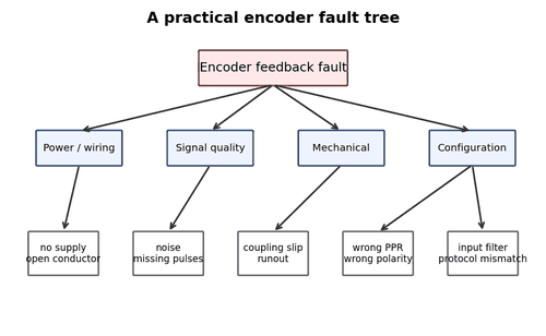
What to Check
- Inspect mounting bolts and bracket.
- Check coupling, hub, clamp, key, and torque arm.
- Inspect cable jacket, bend radius, and strain relief.
- Inspect connector locking and corrosion.
- Check shield termination and cable routing.
- Compare raw count/speed with expected value.
Diagnostic Sequence
- Work through the checks in order.
- Record the observed result, not a guess.
- Correct the first failed layer before moving deeper.
- Repeat the machine cycle to verify the repair.
Common Mistakes
- Skipping a step because the symptom “looks familiar.”
- Replacing multiple parts at once and losing the root cause.
- Leaving temporary test wiring in service.
Field Rule: Use the checklist after any nearby mechanical work, not only on a fixed calendar.
Commissioning Checklist for a New Encoder
Commissioning is where interface and scaling errors should be found, before production.
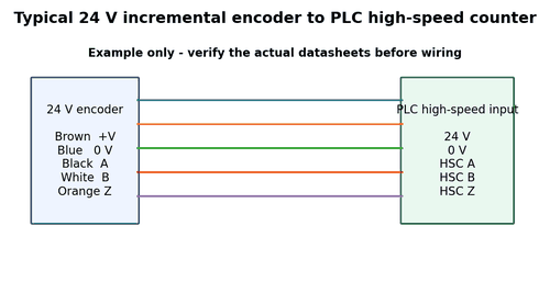
What to Check
- Verify part number and datasheet.
- Confirm supply and output type.
- Confirm pinout.
- Check mechanical alignment.
- Verify raw signal at slow speed.
- Verify direction.
- Verify counts per revolution.
- Verify full-speed signal quality.
- Verify homing/index if used.
- Save configuration backup.
Diagnostic Sequence
- Work through the checks in order.
- Record the observed result, not a guess.
- Correct the first failed layer before moving deeper.
- Repeat the machine cycle to verify the repair.
Common Mistakes
- Skipping a step because the symptom “looks familiar.”
- Replacing multiple parts at once and losing the root cause.
- Leaving temporary test wiring in service.
Field Rule: Commission at low-risk speed first, then prove full operating range.
Replacement Encoder Data to Record
Recording the old installation reduces the chance that a replacement becomes a new fault.
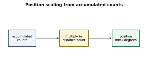
What to Check
- Full part number and suffixes.
- Supply voltage.
- Output interface.
- PPR/resolution.
- Connector and pinout.
- Shaft/hollow-shaft size.
- Mounting style.
- Direction/preset parameters.
- Multiturn range.
- Machine raw position before removal.
Diagnostic Sequence
- Work through the checks in order.
- Record the observed result, not a guess.
- Correct the first failed layer before moving deeper.
- Repeat the machine cycle to verify the repair.
Common Mistakes
- Skipping a step because the symptom “looks familiar.”
- Replacing multiple parts at once and losing the root cause.
- Leaving temporary test wiring in service.
Field Rule: Photograph labels and wiring before disconnecting anything.
Quick Test: No Feedback
Use this short sequence when a machine suddenly reports zero speed or no position change.
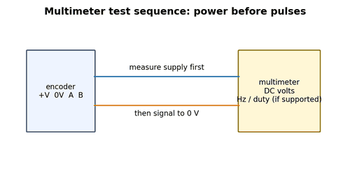
What to Check
- Verify shaft actually moves.
- Verify supply at encoder.
- Check signal at encoder.
- Check signal at receiver.
- Check input diagnostic/count.
- Check software source/scaling.
Diagnostic Sequence
- Work through the checks in order.
- Record the observed result, not a guess.
- Correct the first failed layer before moving deeper.
- Repeat the machine cycle to verify the repair.
Common Mistakes
- Skipping a step because the symptom “looks familiar.”
- Replacing multiple parts at once and losing the root cause.
- Leaving temporary test wiring in service.
Field Rule: Move from physical motion to software interpretation without skipping layers.
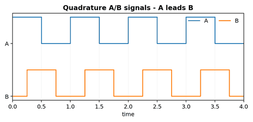
Quick Test: Wrong Direction
Direction faults are usually simpler than general signal faults.
What to Check
- Define physical positive direction.
- Observe A/B phase.
- Check wiring pinout.
- Check HSC/drive direction setting.
- Check mechanical encoder mounting orientation.
Diagnostic Sequence
- Work through the checks in order.
- Record the observed result, not a guess.
- Correct the first failed layer before moving deeper.
- Repeat the machine cycle to verify the repair.
Common Mistakes
- Skipping a step because the symptom “looks familiar.”
- Replacing multiple parts at once and losing the root cause.
- Leaving temporary test wiring in service.
Field Rule: Change only one sign convention at a time.
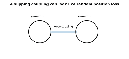
Quick Test: Position Drift
Drift is cumulative, so the test must be repetitive.
What to Check
- Run repeated identical moves.
- Record raw start/end counts.
- Check stationary false counts.
- Mark coupling.
- Reduce speed and acceleration.
- Test cable/EMC.
Diagnostic Sequence
- Work through the checks in order.
- Record the observed result, not a guess.
- Correct the first failed layer before moving deeper.
- Repeat the machine cycle to verify the repair.
Common Mistakes
- Skipping a step because the symptom “looks familiar.”
- Replacing multiple parts at once and losing the root cause.
- Leaving temporary test wiring in service.
Field Rule: Find whether counts are lost, gained, or mechanically decoupled.
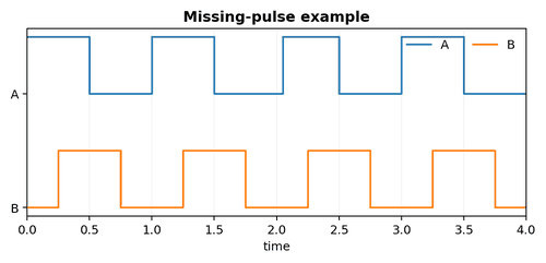
Quick Test: High-Speed Failure
A speed threshold is valuable evidence.
What to Check
- Calculate pulse frequency.
- Check HSC max frequency.
- Check filter/min pulse width.
- Scope at receiver.
- Inspect cable length/interface.
- Check EMI/routing.
Diagnostic Sequence
- Work through the checks in order.
- Record the observed result, not a guess.
- Correct the first failed layer before moving deeper.
- Repeat the machine cycle to verify the repair.
Common Mistakes
- Skipping a step because the symptom “looks familiar.”
- Replacing multiple parts at once and losing the root cause.
- Leaving temporary test wiring in service.
Field Rule: Do not accept a slow-speed pass as proof.
Spare Parts Strategy
Keeping the right spare encoder is harder than keeping “an encoder.” Mechanical fit, electrical interface, resolution, connector, protocol, and configuration all matter.
What to Check
- Standardize part numbers where practical.
- Store adapter pinouts with the spare.
- Keep configuration backups.
- Protect spare shafts and connectors from damage.
Diagnostic Sequence
- Work through the checks in order.
- Record the observed result, not a guess.
- Correct the first failed layer before moving deeper.
- Repeat the machine cycle to verify the repair.
Common Mistakes
- Skipping a step because the symptom “looks familiar.”
- Replacing multiple parts at once and losing the root cause.
- Leaving temporary test wiring in service.
Field Rule: A wrong spare can extend downtime more than no spare at all.
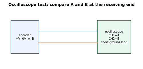
What to Put in the Encoder Troubleshooting Kit
A small dedicated kit speeds diagnosis and prevents improvised probing.
What to Check
- Rated multimeter and leads.
- Portable oscilloscope or approved differential probing solution.
- Breakout adapters.
- Known-good encoder extension cable.
- Small mirror/light and inspection tools.
- Torque tools for couplings.
- Labels, witness paint, and documentation.
Diagnostic Sequence
- Work through the checks in order.
- Record the observed result, not a guess.
- Correct the first failed layer before moving deeper.
- Repeat the machine cycle to verify the repair.
Common Mistakes
- Skipping a step because the symptom “looks familiar.”
- Replacing multiple parts at once and losing the root cause.
- Leaving temporary test wiring in service.
Field Rule: The best tool is often the one that lets you measure without disturbing the connector.
Final Diagnostic Method
A repeatable method beats intuition during a stressful breakdown.
What to Check
- 1. Make the machine safe.
- 2. Define the symptom precisely.
- 3. Identify encoder type/interface.
- 4. Prove mechanical motion.
- 5. Prove power at the encoder.
- 6. Prove signal at the encoder.
- 7. Prove signal at the receiver.
- 8. Verify controller configuration.
- 9. Verify scaling and sequence logic.
- 10. Run repeated validation cycles.
Diagnostic Sequence
- Work through the checks in order.
- Record the observed result, not a guess.
- Correct the first failed layer before moving deeper.
- Repeat the machine cycle to verify the repair.
Common Mistakes
- Skipping a step because the symptom “looks familiar.”
- Replacing multiple parts at once and losing the root cause.
- Leaving temporary test wiring in service.
Field Rule: Document what failed and why so the same fault becomes easier next time.