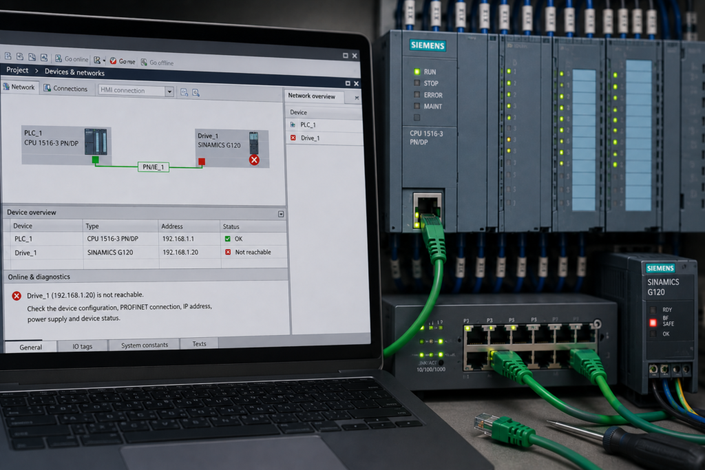
A Siemens PLC reports that a PROFINET device is not reachable, and the remote station disappears from the online hardware view.
The CPU may remain in RUN, but one or more of the following indications appear:
- BF or BUSF LED flashing;
- CPU ERROR or SF LED active;
- ET 200 interface module showing a red diagnostic;
- drive or valve terminal reporting no controller connection;
- TIA Portal showing the device as unavailable;
- diagnostic buffer reporting an I/O device failure;
- process inputs and outputs replaced by substitute values.
The most common causes are:
- device has no power;
- Ethernet cable or switch failure;
- incorrect configured topology;
- wrong PROFINET device name;
- wrong IP subnet;
- replacement device was installed without commissioning.
The device name deserves particular attention.
A PROFINET I/O device must have the expected device name before the IO controller can address it correctly. During startup, the controller can then assign the corresponding configured IP parameters to that named device. Siemens states that an IO device must have a device name before an IO controller can address it, and that the configured IP parameters are normally assigned during startup.
This means that a replacement device can have:
- power;
- a working Ethernet link;
- an IP address;
- the correct part number;
and still remain unreachable because its PROFINET name does not match the name expected by the PLC project.
Quick Troubleshooting Table
| Symptom | Most likely causes |
|---|---|
| Device has no LEDs | Missing 24V supply, blown fuse, broken 0V return or failed device |
| LINK LED is off | Disconnected cable, damaged connector, failed switch port or no power |
| LINK LED is on but BF flashes | Wrong device name, configuration mismatch, wrong controller or device not completing startup |
| Device appears under Accessible devices but remains unavailable to the PLC | Incorrect PROFINET name, wrong hardware configuration or duplicate device name |
| Device can be pinged but PLC reports it as not reachable | Wrong PROFINET name, wrong controller assignment, incorrect project configuration or device addressed through another interface |
| Fault appeared after replacing the device | Replacement has no name, old name, incorrect IP settings or incompatible hardware |
| Fault appeared after moving network cables | Incorrect topology, wrong switch port, broken daisy-chain connection or topology-based replacement failure |
| One device and all downstream devices disappear | Cable, connector or power failure at the last reachable station |
| All PROFINET devices disappear | PLC interface, main switch, trunk cable, controller configuration or common power failure |
| Fault clears after several seconds | Slow device startup, unstable supply, switch delay or insufficient CPU configuration time |
How PROFINET Identifies an I/O Device
PROFINET uses several identifiers, but they do not all serve the same purpose.
MAC Address
The MAC address is a unique hardware identifier assigned to the Ethernet interface.
It is useful when:
- discovering a new device;
- identifying an unnamed replacement;
- assigning a PROFINET name;
- verifying that you are commissioning the correct physical unit.
The PLC project does not normally use the MAC address as the permanent logical identity of the field device.
PROFINET Device Name
The device name is the logical identity expected by the IO controller.
Examples might include:
et200sp-line1;conveyor-drive-2;valve-terminal-01;remote-io-panel-b.
Siemens states that a device name must be assigned before an IO controller can address the IO device for startup configuration or cyclic data exchange.
The configured name must match exactly.
A small difference matters:
Configured name: et200sp-line1
Actual name:     et200sp-line-1
Those are different devices from the controller’s point of view.
IP Address
The IP address enables normal Ethernet and engineering communication.
In a standard configured PROFINET IO system, the controller can assign the project’s IP parameters to the device associated with the expected device name during startup. Siemens notes that IO-device IP addresses are normally assigned automatically at CPU startup and use the controller’s configured subnet information.
This is why changing only the IP address often does not repair a missing PROFINET I/O device.
The name must be correct first.
Hardware Configuration
After identifying the device, the controller also expects the real hardware to match the project.
It may check:
- interface-module type;
- module sequence;
- submodule arrangement;
- drive telegram;
- module firmware;
- configured options.
A device with the correct name and IP can still remain unavailable if its hardware configuration is unacceptable.
Begin With TIA Portal Diagnostics
Do not start by assigning random IP addresses.
Connect to the CPU and open:
Online & Diagnostics → Diagnostics → Diagnostic buffer
Then open the online device view and expand the red diagnostic icons.
Try to identify:
- which PROFINET interface is affected;
- exact configured device name;
- hardware identifier;
- whether the entire device or one submodule is unavailable;
- first incoming event;
- whether the event is current or historical.
Typical messages may include:
- IO device failure;
- device not reachable;
- no frame received;
- station unavailable;
- submodule unavailable;
- configuration difference;
- device name not found;
- wrong or missing component.
Read the First Event in the Fault Chain
Suppose the buffer contains:
- Remote station load voltage missing.
- PROFINET device unavailable.
- Peripheral access error.
- CPU ERROR LED activated.
The missing supply is the original fault.
The communication and I/O errors are consequences.
Fixing the final error message without correcting the first cause will not restore the station.
Check the Online Hardware View
The online device view can narrow the problem from:
CPU → PROFINET interface → remote station → module → submodule
A whole grey or red station normally indicates:
- communication loss;
- missing device;
- power failure;
- naming or configuration problem.
One red module inside an otherwise reachable station indicates a more local hardware or channel problem.
1. The PROFINET Device Has No Power
A network cannot communicate with an unpowered device.
Check power directly at the affected station rather than assuming the main cabinet supply is healthy.
Possible Power Problems
- 24V power supply switched off;
- blown fuse;
- tripped electronic circuit protector;
- loose L+ terminal;
- broken 0V return;
- incorrectly inserted terminal block;
- failed local power supply;
- overloaded supply;
- shorted field circuit pulling down the voltage;
- separate switch power missing.
Check the Device LEDs
Inspect:
- PWR;
- RUN;
- ERROR;
- BF;
- LINK;
- module or load-voltage indicators.
No LEDs at all
Suspect:
- no electronics supply;
- reversed polarity;
- broken return conductor;
- failed interface module.
Power LED on but no LINK
The device is powered, but the Ethernet connection is not established.
Move to the cable and switch checks.
Power and LINK present but BF flashing
The physical link exists.
Check:
- device name;
- controller assignment;
- hardware configuration;
- IP parameters.
Measure the Supply Under Load
Measure between the actual device terminals:
- L+;
- M or 0V.
Do not measure only between L+ and protective earth.
A broken 0V conductor can produce misleading readings relative to earth while the device has no reliable operating supply.
Also measure during:
- device startup;
- output activation;
- contactor operation;
- other heavy 24V loads.
A supply that measures 24V while idle may collapse briefly during startup.
Remote Switch Power
If the device connects through a local Ethernet switch, confirm that the switch itself is powered.
A dead switch can make several field devices disappear at the same time even though every remote I/O station still has power.
2. Cable or Ethernet Switch Failure
A disconnected or damaged network path is another common cause of a PROFINET device becoming unreachable.
Check the LINK LEDs at every relevant point:
- PLC interface;
- main network switch;
- intermediate switch;
- remote device;
- both ports of a daisy-chained station.
LINK LED Off
A missing LINK indication usually points toward a physical Ethernet problem:
- cable unplugged;
- connector not fully inserted;
- failed switch port;
- damaged RJ45 or M12 connector;
- cable conductor broken;
- remote device unpowered;
- Ethernet interface damaged.
LINK LED On
A green LINK LED proves that a physical Ethernet connection exists between two ports.
It does not prove:
- correct PROFINET name;
- correct IP address;
- valid cyclic communication;
- correct hardware configuration;
- correct IO controller assignment.
The device can therefore show LINK while still being reported as not reachable by the PLC.
Check a Daisy-Chain Network
Many PROFINET devices have two integrated Ethernet ports and are connected in a line.
If one device or cable section fails, every station downstream can disappear.
Use the fault pattern:
- find the last reachable station;
- identify the first unreachable station;
- inspect the cable between them;
- inspect the outgoing port on the last healthy device;
- inspect the incoming port on the first failed device.
The fault is often located between those two points.
Test With a Known-Good Cable
Where safe and practical:
- Connect the device using a short known-good industrial Ethernet cable.
- bypass the suspected cable section.
- use an approved switch port.
- check whether LINK and PROFINET communication return.
If communication works, inspect the original:
- cable;
- field connector;
- patch panel;
- cabinet feed-through;
- switch port.
Switch Configuration Problems
A managed switch can have a healthy physical port while still preventing required traffic.
Check:
- port enabled state;
- VLAN assignment;
- port security;
- redundancy configuration;
- multicast or PROFINET settings;
- DCP or LLDP boundaries;
- duplicate network paths.
DCP is used for automatic PROFINET detection and basic configuration. Siemens notes that DCP requires suitable access to PROFINET components, while configured port boundaries can prevent discovery traffic from being forwarded.
3. Incorrect PROFINET Topology
The network view and topology view in TIA Portal are not the same.
The network view shows logical communication relationships.
The topology view shows which physical Ethernet port is connected to which neighboring port. Siemens describes the topology view as representing Ethernet components, cables, switches and their physical interconnections.
Does Incorrect Topology Always Stop Communication?
No.
Basic PROFINET RT communication can often work without a fully configured topology.
Topology becomes especially important for functions such as:
- topology diagnostics;
- IRT planning;
- media redundancy;
- port-specific diagnostics;
- device replacement without a programming device.
Therefore, an incorrect topology does not automatically explain every unreachable device.
However, it becomes a major suspect when:
- the device was replaced;
- automatic naming was expected;
- cables were moved to different ports;
- the project uses topology-based device replacement;
- TIA Portal reports topology differences;
- the controller cannot identify an unnamed replacement.
Topology-Based Device Replacement
For supported systems, the IO controller can identify an unnamed replacement device from its physical neighbor relationships.
The controller compares:
- configured topology;
- actual neighboring devices;
- actual port connections.
It can then assign the replacement the configured device name and IP parameters.
Siemens states that topology-based replacement uses the configured topology and neighbor relationships determined by the IO devices. The involved equipment must support the required topology functions, including LLDP.
If the replacement is plugged into the wrong port, the controller may be unable to determine which configured station it should become.
Typical Topology Problems
- Device connected to the wrong switch port.
- IN and OUT cables reversed relative to the configured topology.
- New unmanaged switch inserted without updating the design.
- Physical line changed to a star.
- Device moved to another machine section.
- LLDP disabled or blocked.
- Project topology does not match the real cable path.
- Controller expects automatic replacement, but the device does not support it.
Check the Topology Comparison
In TIA Portal:
- Open Devices & networks.
- select Topology view.
- open the online/offline topology comparison.
- compare configured and detected neighboring ports.
- identify missing or unexpected links.
- correct the physical connection or approved project topology.
Siemens provides an online/offline topology comparison that reports the status of devices and ports and helps identify differences between configured and detected topology.
Do Not Edit Topology Just to Remove the Alarm
First determine whether the physical wiring or the project is correct.
Changing the project to match an accidental cable connection can break:
- automatic device replacement;
- maintenance documentation;
- IRT configuration;
- redundancy;
- future troubleshooting.
4. Wrong PROFINET Device Name
The wrong device name is one of the most common reasons a powered, physically connected device remains not reachable.
A new device may be delivered without a configured name.
A used spare device may retain the name of another station.
A replacement drive may have:
- a factory name;
- an old machine name;
- no name;
- a duplicate name.
The controller searches for the name configured in the project.
If that name is not present, it cannot associate the physical unit with the intended I/O station. Siemens explicitly states that PROFINET devices must have an assigned name before they can connect correctly to the CPU.
Check the Configured Name
In TIA Portal:
- Open Devices & networks.
- select the affected device.
- open its PROFINET interface properties.
- record the configured PROFINET device name.
Copy the name exactly.
Do not rely on:
- device title in the project tree;
- cabinet label;
- descriptive tag;
- IP address.
The configured PROFINET name is the relevant value.
Find the Online Device
Open:
Online → Accessible devices
Select the correct PG/PC Ethernet interface and scan the local network.
Identify the physical device using:
- MAC address;
- device type;
- current name;
- IP address;
- Flash LED function.
Siemens instructs users to select the intended IO device by MAC address and provides a Flash LED function to verify the physical device before assigning its name.
Assign the Correct Name
Use:
Assign PROFINET device name
Then:
- select the correct PG/PC adapter;
- scan for devices;
- select the physical device;
- use Flash LED where supported;
- choose the configured project name;
- assign it;
- wait for the PLC to establish cyclic communication.
Do not assign the correct name to the wrong physical device.
On a machine with several identical ET 200 stations, that can create a second fault while leaving the original one unresolved.
Duplicate Device Name
Device names must be unique within the relevant PROFINET IO network.
If two devices use the same name, the controller cannot reliably associate the configured identity with one physical station.
Possible symptoms include:
- one device remains unavailable;
- communication changes when another station is powered;
- duplicate-name diagnostics;
- wrong station becomes active;
- fault appears intermittently.
Disconnect or power devices individually only under approved process conditions, and identify them by MAC address.
Name Looks Correct but Device Remains Missing
Check for hidden differences:
- additional hyphen;
- omitted number;
- spelling;
- name assigned to another Ethernet interface;
- duplicate name;
- wrong physical device selected;
- project not downloaded after renaming the configured station.
5. Wrong IP Address or Subnet
PROFINET cyclic startup depends strongly on the device name, but the configured IP settings still need to be valid.
Possible problems include:
- device on the wrong subnet;
- incorrect subnet mask;
- duplicate IP address;
- static IP left from another machine;
- wrong PLC PROFINET interface;
- device and controller configured in different subnets;
- incorrect router settings.
Siemens states that devices communicating directly without a router must be in compatible IP subnets.
Example of a Wrong Subnet
PLC interface
IP address: 192.168.10.1
Subnet mask: 255.255.255.0
Device
IP address: 192.168.20.25
Subnet mask: 255.255.255.0
These addresses belong to different /24 subnets.
The device may still appear under local PROFINET discovery because discovery and normal IP routing are not identical, but standard IP communication will not operate correctly without routing or corrected parameters.
Let the Controller Assign the Configured IP
In many standard PROFINET IO systems, the most reliable commissioning order is:
- assign the correct device name;
- ensure the project contains the correct IP address;
- download the controller configuration;
- allow the controller to assign or confirm the configured IP during startup.
Siemens notes that the IO controller normally assigns the configured IP parameters during startup once the device can be identified correctly.
Duplicate IP Address
A duplicate IP can cause:
- intermittent communication;
- wrong device answering ping;
- online access switching between MAC addresses;
- PROFINET startup errors;
- device appearing and disappearing.
To check:
- record the device’s MAC address;
- inspect Accessible devices;
- inspect the PC ARP table;
- temporarily disconnect the suspected device where safe;
- test whether the IP still responds.
Do not select a replacement IP simply because it appears unused at that moment.
It may belong to equipment that is currently powered down.
Controller Has Multiple PROFINET Interfaces
Some Siemens CPUs have separate interfaces such as X1 and X2.
Each may belong to a different subnet.
Confirm that the remote device is configured under the same physical and logical CPU interface to which it is actually connected.
Siemens requires multiple PROFINET interfaces on one CPU to use different IP subnets.
6. Device Replaced Without Commissioning
A common sequence is:
- Original ET 200 interface or drive fails.
- Maintenance installs an identical spare.
- Ethernet and power are connected.
- The replacement shows LINK.
- PLC still reports “device not reachable.”
The replacement may not yet have the identity expected by the PLC.
What a Replacement Device May Be Missing
- PROFINET device name;
- correct IP parameters;
- matching firmware;
- approved hardware configuration;
- drive parameters;
- memory card or removable configuration medium;
- topology-based replacement support.
Manual Commissioning Method
When automatic device replacement is not enabled or supported:
- connect the replacement.
- power it.
- open Accessible devices.
- identify it by MAC address.
- use Flash LED to verify its location.
- assign the project’s PROFINET device name.
- confirm the controller assigns the correct IP.
- download device-specific configuration where required.
- verify that cyclic data exchange starts.
Automatic Device Replacement
Supported Siemens controllers and IO devices can use device replacement without a programming device or exchangeable medium.
Depending on the equipment and configuration, the controller can identify an unnamed replacement through:
- configured topology;
- actual LLDP neighbor relationships;
- supported alternative replacement mechanisms.
Siemens documentation explains that the controller can use the configured topology and real neighbor relationships to identify an unnamed replacement and assign its configured name and IP address.
This requires the necessary function to be configured and supported by the controller, replacement device and surrounding network equipment.
Do not assume every PROFINET device supports automatic replacement.
Used Spare Device
A spare taken from another machine may already contain:
- another PROFINET name;
- another IP address;
- old drive parameters;
- incompatible configuration.
Some automatic replacement functions expect an unnamed or factory-state device unless the controller is configured to overwrite existing names. Siemens documents an S7-1500 option that can permit the controller to overwrite assigned IO-device names during startup for supported applications.
Resetting a device to factory settings may help prepare it for recommissioning, but only after:
- current parameters have been backed up;
- device-specific settings are understood;
- the replacement procedure has been confirmed.
A drive or intelligent field device may contain much more than its PROFINET identity.
7. Hardware Configuration Does Not Match
A device can be correctly named and reachable over Ethernet but still fail to enter cyclic I/O exchange.
The controller may reject it because the installed hardware does not match the downloaded configuration.
Possible Mismatches
- wrong interface-module order number;
- incompatible successor model;
- different firmware version;
- missing I/O module;
- modules installed in the wrong order;
- incorrect drive telegram;
- wrong safety module;
- incorrect submodule;
- station contains extra or missing components.
Typical Diagnostic Message
The PLC may report something similar to:
- unacceptable configuration difference;
- wrong or missing component;
- submodule unavailable;
- module type mismatch;
- parameter assignment error.
Check the Complete Device
Compare:
- interface-module order number;
- firmware;
- every installed I/O module;
- BaseUnits or carrier arrangement where relevant;
- server module;
- safety configuration;
- configured telegrams.
Do not compare only the main product family.
Two ET 200 interface modules can look nearly identical while supporting different functions or module arrangements.
8. Device Startup Takes Too Long
A device may temporarily be shown as not reachable if it does not complete startup before the CPU’s configured startup timing expires.
Possible reasons include:
- remote device starts slowly;
- switch requires time to establish links;
- drive performs internal checks;
- several stations power up sequentially;
- unstable 24V supply causes repeated restart;
- configured startup time is too short.
Siemens documents a configurable CPU startup period for PROFINET stations and warns that insufficient configuration time can generate false station errors before all devices complete startup.
How to Recognise It
- Fault appears only during power-up.
- Device becomes healthy later without intervention.
- Diagnostic event changes to outgoing.
- Fault is worse after full plant power loss.
- Warm restart works but cold restart produces errors.
Correct Response
First confirm the device is not restarting because of a real power or network problem.
Only then review:
- CPU configuration time;
- device startup specifications;
- switch and redundancy startup;
- sequence of power supplies.
Do not increase startup timers simply to hide an unstable device.
9. Wrong IO Controller or Controller Assignment
A PROFINET device can be connected to the network yet configured under the wrong controller or PROFINET interface.
This can happen after:
- copying a project;
- adding a second PLC;
- moving a device between IO systems;
- replacing a CPU;
- editing network assignments.
Check in TIA Portal that the device is connected logically to:
- the intended PLC;
- the correct CPU PROFINET interface;
- the correct IO system.
A physical Ethernet connection alone does not assign the device to the correct IO controller.
Complete Step-by-Step Troubleshooting Procedure
Step 1: Make the Process Safe
A failed remote station can cause outputs to:
- de-energise;
- hold their last value;
- use substitute values;
- move equipment unexpectedly after communication returns.
Control hazardous energy before reconnecting or recommissioning the device.
Step 2: Read the Diagnostic Buffer
Record:
- device name;
- interface;
- hardware identifier;
- first incoming event;
- configuration or communication details.
Step 3: Check Device Power
Verify L+, M and local protective devices.
Step 4: Check LINK LEDs
If LINK is absent, troubleshoot:
- cable;
- connector;
- switch;
- device power;
- Ethernet port.
Step 5: Check the Fault Pattern
Determine whether:
- one device is missing;
- several devices downstream are missing;
- every PROFINET device is missing.
Step 6: Scan Accessible Devices
Use the correct PG/PC Ethernet adapter.
Identify the station by MAC address.
Step 7: Compare the Device Name
Compare the online name with the project’s configured PROFINET name.
Step 8: Assign the Correct Name
Use Flash LED before naming identical devices.
Step 9: Check IP and Subnet
Confirm:
- unique IP;
- correct subnet mask;
- correct CPU interface;
- no duplicate address.
Step 10: Compare Hardware Configuration
Check the complete order number, firmware and module arrangement.
Step 11: Check Topology
Especially when:
- device was replaced;
- cables were moved;
- automatic replacement is enabled;
- topology diagnostics report a mismatch.
Step 12: Review Device Replacement Requirements
Confirm that the controller and device support the configured replacement method.
Step 13: Restart Communication
After correcting the cause:
- allow the device to restart;
- confirm BF turns off;
- check for an outgoing diagnostic;
- verify that the device becomes green online.
Step 14: Test Process Data
Confirm:
- inputs update;
- outputs respond;
- quality status is valid;
- drive or valve control works;
- safety devices are correctly commissioned.
Symptom-Based Troubleshooting
Device Has No Power or LEDs
Check:
- local 24V supply;
- fuse or circuit protector;
- 0V return;
- polarity;
- terminal connector;
- device hardware.
Power Is On but LINK Is Off
Check:
- Ethernet cable;
- connector;
- switch power;
- switch port;
- correct device socket;
- known-good test cable.
LINK Is On but BF Flashes
Check:
- PROFINET device name;
- controller assignment;
- hardware configuration;
- IP settings;
- startup diagnostics.
Device Appears Under Accessible Devices but PLC Cannot Reach It
Check:
- exact device name;
- duplicate name;
- configured IO controller;
- hardware mismatch;
- correct CPU interface.
Fault Appeared After Device Replacement
Check:
- device name;
- factory-state or old spare configuration;
- order number;
- firmware;
- topology-based replacement support;
- device-specific parameter download.
Fault Appeared After Cables Were Moved
Check:
- actual port-to-port connections;
- configured topology;
- last reachable device;
- wrong switch port;
- daisy-chain continuity;
- LLDP or topology functions.
Device Can Be Pinged but Is Not in Cyclic I/O Exchange
Check:
- expected PROFINET name;
- correct IO controller;
- hardware configuration;
- duplicate identity;
- device compatibility.
Ping proves IP reachability.
It does not prove that the PLC recognises the device as the configured PROFINET I/O station.
Device Becomes Reachable After a Delay
Check:
- startup time;
- power stability;
- switch startup;
- redundancy recovery;
- repeated device rebooting.
What Not to Do
Avoid these common mistakes:
- Do not replace the PLC because a remote device is unreachable.
- Do not change only the IP address and ignore the device name.
- Do not assign the correct name to an unidentified MAC address.
- Do not give two devices the same name.
- Do not give two devices the same IP address.
- Do not edit topology merely to match accidental cabling.
- Do not assume every replacement commissions itself automatically.
- Do not factory-reset an intelligent device before backing up its parameters.
- Do not disable diagnostics to remove the alarm.
- Do not assume a green LINK LED means PROFINET communication is healthy.
- Do not download hardware changes without making the process safe.
- Do not reconnect a failed remote station without checking how outputs will respond.
The objective is not merely to remove the red icon in TIA Portal.
The objective is to restore communication with the correct physical device, using the correct identity and configuration.
Why the PROFINET Device Is Not Reachable
A PROFINET device is reported as not reachable when the IO controller cannot identify it, contact it or establish the configured cyclic I/O relationship.
The main causes are:
- device power failure;
- cable or Ethernet switch failure;
- incorrect topology;
- wrong PROFINET device name;
- wrong IP subnet;
- replacement without commissioning;
- hardware mismatch;
- excessive startup delay.
Use this diagnostic order:
Power → LINK → Accessible devices → device name → IP/subnet → hardware → topology
The most important rule is:
The controller looks for the configured PROFINET device name. Once it identifies the correctly named device, it can apply the corresponding configured IP parameters and begin startup communication.
An IP address tells the Ethernet network where a device is.
The PROFINET name tells the PLC which device it is.