
A contactor or relay never works alone — it sits in a control circuit, and reading that circuit is essential to troubleshooting the device, because a fault that looks like the device is often really a fault in the circuit around it. The particular challenge is that a contactor appears in more than one place on the drawing: its coil in the control circuit, and its contacts wherever they switch something. Understanding how to read a circuit that shows one device in pieces, connected by a shared label, is the key skill this chapter teaches.
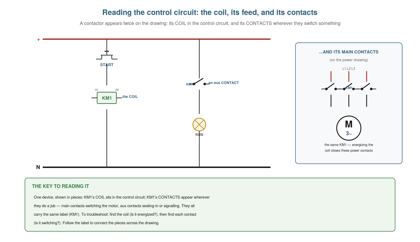
One device, shown in pieces
The central idea in reading a control circuit is that one device is shown in pieces across the drawing, linked by its label, and understanding this lets you follow a contactor or relay through the whole circuit. A contactor’s coil appears in one place (in the control circuit, where it is energized), and its contacts appear elsewhere (wherever they switch something — main contacts on the power drawing switching the motor, aux contacts in control rungs sealing-in or signalling). All these pieces carry the same label (KM1), which is how you know they belong to the same device. So the drawing shows the coil and the several contacts of one contactor as separate symbols, connected only by their shared label. Understanding this lets you assemble the whole device from its pieces: find the coil by its label, find each contact by the same label, and understand how energizing the coil operates all those contacts. For troubleshooting, this is essential: to diagnose a contactor, you find its coil (is it energized?) and each of its contacts (is it switching?), following the label across the drawing. So understanding that one device is shown in pieces, linked by label, lets you follow and troubleshoot a contactor through the whole circuit. Understanding that one device is shown in pieces — the coil in one place and the contacts wherever they do their jobs, all connected by the shared label — lets you follow a contactor or relay through the whole control circuit, so that you can assemble the device from its scattered symbols by following the label, find its coil and each of its contacts, and understand how energizing the coil operates them all, which is the essential skill for troubleshooting a device that the drawing deliberately spreads across the circuit and links only by name.
Following the coil to its contacts
The practical technique is following a device from its coil to its contacts (and back), and understanding it lets you connect a coil’s state to what its contacts should be doing. When you find a contactor’s coil in the control circuit and determine whether it is energized, you then know what all its contacts should be doing: if the coil is energized, its NO contacts should be closed and its NC contacts open; if de-energized, the reverse. So by following the coil’s label to each of its contacts, you can predict the state of every contact from the state of the coil. This connects the control logic to the switched circuits: energizing KM1’s coil closes KM1’s main contacts (starting the motor) and KM1’s seal-in aux contact (holding the coil in). For troubleshooting, following the coil to its contacts lets you check consistency: if the coil is energized but a contact is not in the state it should be, that contact is faulty. So understanding how to follow the coil to its contacts lets you connect the coil’s state to the contacts’ expected states and spot a faulty contact. Understanding how to follow the coil to its contacts — using the coil’s state to predict what each of its contacts should be doing, since an energized coil closes its NO and opens its NC contacts — lets you connect a coil’s state to what its contacts should be doing, so that you can predict every contact’s state from the coil’s, connect the control logic to the switched circuits, and check consistency (a contact not in the state the coil’s condition dictates is faulty), which turns following the device across the drawing into a practical way to reason about whether its contacts are behaving as the coil’s state requires.
Aux contacts and feedback in the circuit
A particular thing to understand in reading control circuits is the role of auxiliary contacts and feedback, because they appear throughout the control logic and understanding them explains much of how the circuit works. A contactor’s aux contacts appear in the control circuit doing control jobs: an aux contact wired parallel to the start button provides seal-in; an aux contact in another contactor’s coil circuit provides interlocking; an aux contact feeding a signal back tells the control system (or an indicator) the contactor’s state. So the aux contacts are how a contactor participates in the control logic — sealing itself in, interlocking with others, signalling its state. Understanding this explains the control circuit: many of the contacts you see in control rungs are aux contacts of contactors, doing these logic jobs. For troubleshooting, it means an aux contact fault has specific effects: a failed seal-in aux drops the contactor out when start is released; a failed interlock aux allows or prevents another contactor wrongly; a failed feedback aux misreports the state. So understanding aux contacts and feedback in the circuit explains the control logic and the specific effects of aux-contact faults. Understanding aux contacts and feedback in the circuit — the auxiliary contacts appearing throughout the control logic to provide seal-in, interlocking, and state feedback — explains much of how the control circuit works, so that you recognize many of the contacts in control rungs as aux contacts doing logic jobs, and you understand the specific effects of their faults (a failed seal-in dropping the contactor out, a failed interlock wrongly allowing or preventing another contactor, a failed feedback misreporting the state), which lets you read the control circuit’s logic and diagnose the aux-contact faults that produce these characteristic control-level symptoms.
Contact cross-references and coil contact maps
A feature of real control drawings worth understanding is the contact cross-reference, because it lets you find all of a contactor’s contacts across a multi-sheet drawing. On a professional schematic, a contactor’s coil symbol is accompanied by a contact map or cross-reference: a table or list showing where each of its contacts appears (which sheet and location), and what type each is (NO, NC). This is necessary because the contacts are scattered across the drawing (main contacts on the power sheet, aux contacts in various control rungs), and without the cross-reference you could not find them all. Understanding how to read this map lets you locate every contact of a contactor: you read its coil’s contact list and follow each reference to find that contact on the drawing. For troubleshooting, this is essential — to check all of a contactor’s contacts, you must be able to find them, and the cross-reference is how. So understanding contact cross-references and coil contact maps lets you find all of a contactor’s contacts across the drawing. Understanding contact cross-references and coil contact maps — the table beside a coil symbol showing where each of its contacts appears and what type it is — lets you find all of a contactor’s contacts across a multi-sheet drawing, so that you can locate every contact (main contacts on the power sheet, aux contacts in control rungs) by reading the coil’s contact list and following each reference, which is essential for troubleshooting because checking all of a device’s contacts requires finding them, and the cross-reference is the means by which the drawing tells you where they are.
Scenario: following the label to the fault
A scenario shows how reading the control circuit by following the label locates a fault. A motor would not start, and the technician read the circuit rather than guessing. He found KM1’s coil in the control circuit and determined it was not energizing. Following KM1’s label, he checked the coil circuit — the series path of contacts feeding the coil — and, using the contact cross-reference, identified each contact in that path. One was an aux contact of another contactor, KM3, wired as an interlock. He checked KM3: it was energized, so its NC aux contact (in KM1’s coil circuit) was open, holding KM1 off. That was the interlock doing its job — KM3 was on when it should not have been, which was the real issue to pursue. Following the labels through the circuit had led him from the dead motor to the interlock and the contactor actually at fault. This scenario shows how reading the circuit by following labels locates the real fault. Understanding how to follow a device’s label through the circuit led the technician from KM1’s unenergized coil to the interlocking KM3. It reinforces that following labels and cross-references through the control circuit locates the real source of a fault. The scenario reinforces reading the control circuit: following KM1’s label through its coil circuit and the contact cross-references led the technician to the interlocking KM3 holding it off, illustrating how reading the circuit by following labels and cross-references traces a fault from the visible symptom (a dead motor) to its real source (an interlock and the contactor behind it), which blind part-swapping would never have found.
Tracing a rung from live to neutral
A practical reading-and-measuring technique worth understanding is tracing a control rung from the live rail to neutral, because it connects reading the circuit to measuring it. A control rung runs from one supply rail (live/positive) through a series of contacts and the coil to the other rail (neutral/return). Reading the rung tells you the series of elements the current passes through; measuring lets you find where, in that series, the path is broken. The technique: with the reference lead on neutral, probe down the rung from the live rail through each element — as long as you read the supply voltage, the path is good to there; where the voltage disappears is the open element. So reading the rung (knowing the elements in order) and tracing it with the meter (finding where voltage vanishes) together locate a fault. Understanding this connects reading to measuring: you read the rung to know what to trace, then trace it to find the break. This is divide-and-conquer applied to a control rung. So understanding tracing a rung from live to neutral connects reading the circuit to measuring it to locate a fault. Understanding how to trace a control rung from live to neutral — reading the series of elements the rung passes through, then probing down it from the live rail with the reference on neutral to find where the voltage disappears (the open element) — connects reading the circuit to measuring it, so that you use your reading of the rung to know what to trace and the meter to find the break, applying divide-and-conquer to the control rung, which turns understanding the circuit’s structure into the practical ability to locate an open in it by tracing where the voltage is lost.
The circuit as the map you troubleshoot by
To close, it helps to see the control circuit drawing as the map you troubleshoot by, because reading it well is what makes diagnosis navigation rather than wandering. The drawing shows what should happen — which coil energizes when, what each contact switches, how the pieces of each device connect by their labels. Reading it gives you the map: you know the intended operation, where each device’s coil and contacts are, and how to trace a fault through the circuit. Without the map, troubleshooting is wandering; with it, you navigate from the symptom to the fault. So the control circuit drawing is your map, and reading it — following labels, cross-references, and the logic — is how you navigate. Understanding this captures why reading the circuit is so central. So seeing the circuit as the map you troubleshoot by captures why reading it is central. Understanding the control circuit drawing as the map you troubleshoot by — showing the intended operation, each device’s coil and scattered contacts linked by labels, and the logic, so that reading it lets you navigate from symptom to fault — captures why reading the circuit is central, so that you approach every fault with the map that tells you what should happen and how to trace the fault through the circuit, which turns troubleshooting from aimless wandering into purposeful navigation and is the deeper reason reading the control circuit is a foundational skill.