
Most industrial power is three-phase, and three-phase power schematics have a characteristic appearance that, once understood, reads clearly. The motor power circuit is the most common three-phase schematic a technician meets, and it follows a consistent top-to-bottom structure.
Three phases, read together
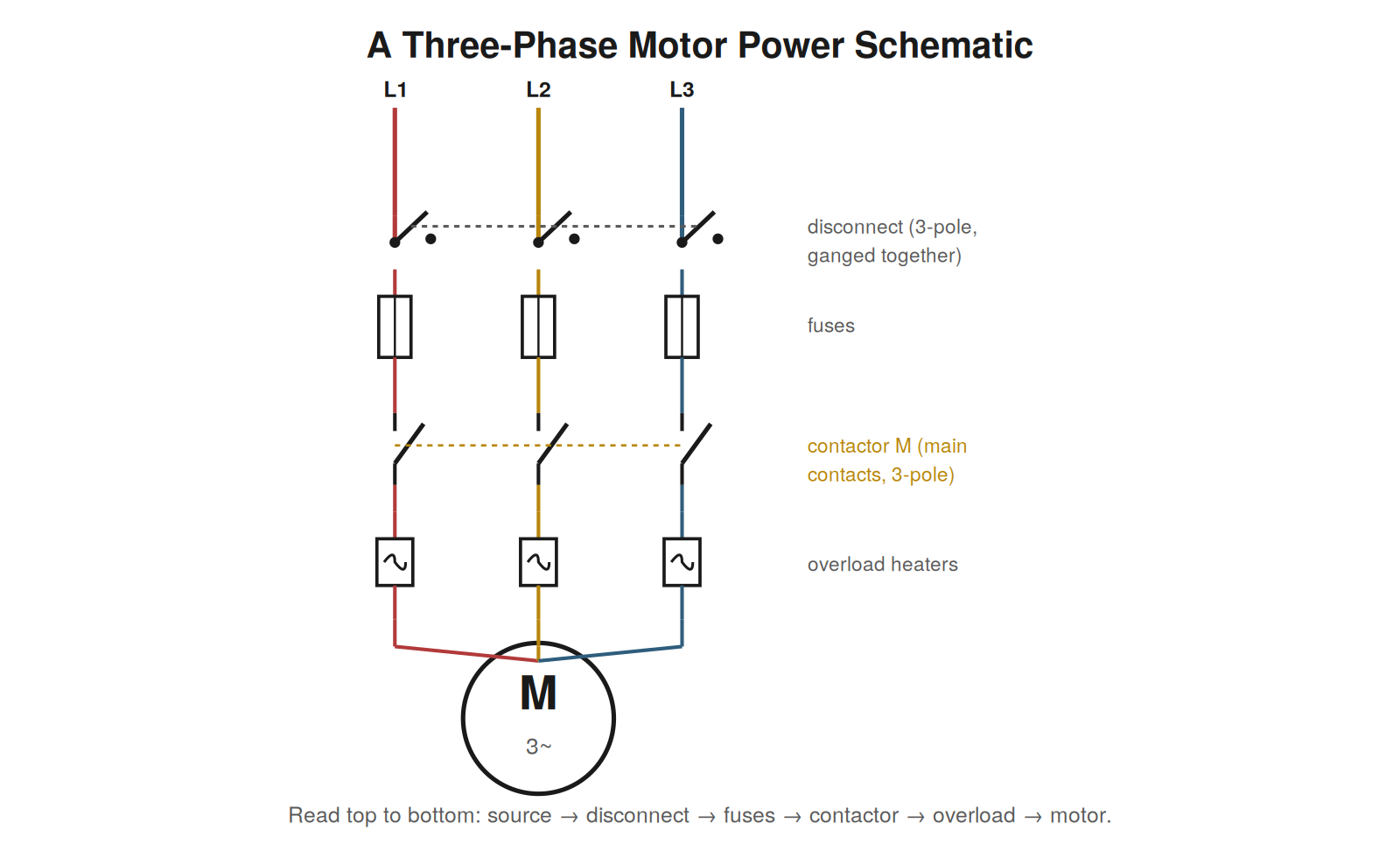
A three-phase power schematic shows three supply lines — L1, L2, L3 — running in parallel from the source to the load, and the reading approach is to see them as three parallel paths that pass together through each device. A three-pole disconnect opens all three at once; three fuses protect each phase; the contactor’s three main contacts switch all three together; three overload heaters sense each phase’s current. Each device acts on all three phases simultaneously, which is why they are drawn ganged together, often with a dashed line linking the three poles to show they operate as one. Reading a three-phase schematic means following the three phases down through this series of three-pole devices to the motor, seeing each device as acting on all three phases at once. The structure is repetitive across the three phases, which makes it read cleanly once the pattern is recognized.
The standard motor circuit structure
The three-phase motor circuit follows a standard order from source to motor, and knowing this order lets you read it quickly and know what to expect. From the top: the three-phase supply enters; a disconnect provides isolation; fuses or a breaker provide short-circuit protection; the contactor’s main contacts switch the motor on and off under control of the coil; overload heaters sense the motor current for overload protection; and finally the three phases reach the motor. Reading this structure top to bottom tells the motor’s power story: where it can be isolated, where it is protected, where it is switched, and where its current is monitored. This standard order — disconnect, protection, contactor, overload, motor — recurs across countless motor circuits, and recognizing it means you can read a three-phase motor schematic almost at a glance, knowing what each stage does and where to look when the motor has no power.
Reading faults from the structure
The standard structure also guides troubleshooting a dead three-phase motor, because it tells you the sequence of things to check from source to motor. Working down the drawing: is power present at the supply, is the disconnect closed, are the fuses intact or the breaker on, are the contactor’s main contacts closing (is the coil energized?), are the overload heaters and their contact intact, and does power reach the motor? Each stage on the drawing is a checkpoint, and reading the structure tells you the order to check them and what should be present at each. A missing phase somewhere in this chain — a blown fuse in one phase, a failed contact — is a common and serious fault, found by checking the three phases at successive points down the drawing until the one where a phase disappears is localized. The schematic’s structure, read from source to motor, becomes the map for finding where the power stops.
Reading a lost-phase fault from the structure
A particularly instructive three-phase fault is a lost phase — one of the three phases missing — and the schematic’s structure is exactly the tool to find where it is lost. A motor running on two of three phases behaves badly: it may hum, struggle, overheat, or trip, and the cause is one phase missing somewhere in the chain from source to motor. Reading the three-phase schematic top to bottom, you have a series of points to check each phase: at the supply, below the disconnect, below the fuses, below the contactor contacts, below the overloads. Checking all three phases at successive points down the drawing, you find the point where three phases are present above but only two below — and that device is where the phase is lost, whether a blown fuse in one phase, a failed pole of the contactor, or an open connection. The schematic’s repetitive three-phase structure makes this systematic: it gives you the checkpoints and the order, turning a lost-phase fault into a methodical descent through the drawing until the missing phase is localized to one device.
Reading exercise: locating the checkpoints
Build fluency with three-phase schematics by taking a motor circuit and identifying, on the drawing, every point where you could check the three phases — the checkpoints for a lost-phase or dead-motor fault. Mark the supply, below the disconnect, below the fuses, below the contactor contacts, below the overloads, at the motor. At each, all three phases should be present when the circuit is energized and the contactor closed. Identifying these checkpoints on the drawing, before any fault occurs, builds the mental map that makes troubleshooting fast when a fault does occur: you already know where to check and what should be present. The exercise also reinforces the standard structure of the motor circuit, since the checkpoints fall between its standard stages. Practicing it on various motor circuits builds the habit of seeing the three-phase schematic as a series of checkpoints from source to motor, so that a dead or misbehaving motor prompts a systematic descent through those checkpoints rather than a disorganized search, and the point where a phase disappears is found methodically.
Reading transformer and distribution symbols
Beyond the motor circuit, three-phase drawings often include transformers and distribution that reading correctly requires understanding. A three-phase transformer, changing voltage between distribution levels, appears as coupled windings and may be drawn with its configuration indicated. Distribution — how power divides among multiple loads from a common source — appears as the branching of the supply to feeders, each protected and switched. Reading these means following the power from its incoming supply, through any transformation, as it distributes to the various loads, understanding the structure of the power system above the individual motor circuit. This wider reading places a motor circuit in context: it is fed from a distribution that comes from a supply possibly transformed from a higher voltage, and understanding this context helps in troubleshooting problems that originate upstream of a single motor — a distribution-level fault affecting several loads, a transformer issue affecting everything it feeds. Reading the transformer and distribution symbols extends your reading from the individual motor circuit up to the power system that feeds it, which matters when a fault is not in one motor’s circuit but in the distribution or supply that serves many circuits at once.
Reading motor connection details
The motor end of a three-phase schematic may show connection details — how the motor’s windings connect — that reading correctly matters for certain faults and for understanding the motor’s operation. A three-phase motor’s windings can be connected in different configurations, and some motors allow different connections for different voltages or for starting methods like star-delta starting, where the connection changes during starting to reduce inrush. Reading these connection details on the drawing tells you how the motor is connected and, for motors with switchable connections, how the connection changes during operation. This matters for troubleshooting motor circuits where the connection is part of the function — a star-delta starter, for instance, involves contactors that reconfigure the motor connection during starting, and reading the drawing reveals this sequence. While a basic motor circuit simply connects the three phases to the motor, more sophisticated ones involve connection details that the drawing shows and that reading reveals. Understanding these — the motor’s winding connection and any switching of it during operation — completes the reading of the motor end of a three-phase schematic, extending from the simple three-phase connection to the more involved connections that some motor circuits use for voltage selection or reduced-inrush starting.
Case: the single-phasing motor
Single-phasing — a three-phase motor losing one phase — is a serious fault that reading the three-phase schematic locates methodically. A motor was struggling, overheating, and drawing unusual current, symptoms consistent with running on two phases instead of three. Reading the three-phase schematic, the technician checked the three phases at successive points down the drawing: at the supply, below the disconnect, below the fuses, below the contactor, below the overloads. At each checkpoint, all three phases should be present. Descending through the checkpoints, the technician found a point where three phases were present above but only two below — localizing the lost phase to the device at that point, a blown fuse in one phase. Reading the schematic’s structure provided the checkpoints and the systematic descent that located exactly where the phase was lost. This case shows reading the three-phase structure to diagnose single-phasing: the drawing’s repetitive three-phase structure gives checkpoints from source to motor, and checking all three phases at each, descending until one disappears, localizes the loss to a specific device. Single-phasing is damaging and its symptoms are distinctive, and reading the three-phase schematic to check phases methodically down the drawing is how the lost phase is found, turning a struggling motor into a located fault at the device where the third phase disappears.
The three-phase motor circuit as a template
The standard three-phase motor circuit, once learned, serves as a template that makes reading the countless motor circuits you will encounter fast and familiar, because they are largely variations on this template. The structure — supply, disconnect, protection, contactor, overload, motor — recurs across motor circuits everywhere, so learning it once equips you to read most motor circuits at a glance, recognizing the template and noting any variations. This is a specific instance of the general power of pattern recognition: the three-phase motor circuit is a pattern so common that recognizing it accelerates the reading of a huge class of circuits. Variations exist — different starting methods, additional protection, control refinements — but they are variations on the recognizable template, read as ‘the standard motor circuit, plus this variation.’ Internalizing the standard three-phase motor circuit as a template is therefore high-leverage, because motor circuits are ubiquitous and mostly follow it. The reader who knows the template reads motor circuits quickly, recognizing the familiar structure and focusing on any variations, rather than analyzing each motor circuit from scratch. The three-phase motor circuit is worth learning thoroughly as a template precisely because it recurs so often, and knowing it makes the reading of motor circuits — a large part of industrial electrical work — fast and familiar.