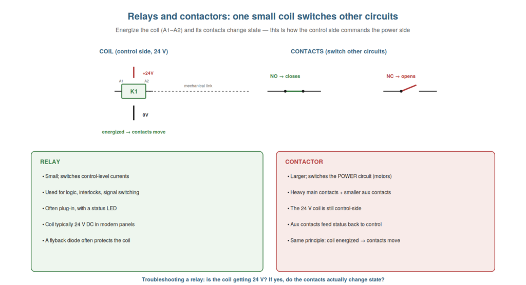
Relays and contactors are the devices by which a small control signal switches other, larger circuits — the bridge between the control side and the power side — and understanding how they work is essential to troubleshooting the many faults involving them. A relay or contactor has a coil that, when energized, moves its contacts; understanding this coil-and-contacts operation lets you diagnose whether the fault is in the coil not energizing or the contacts not switching. This chapter covers relays and contactors from the maintenance perspective.
Coil and contacts
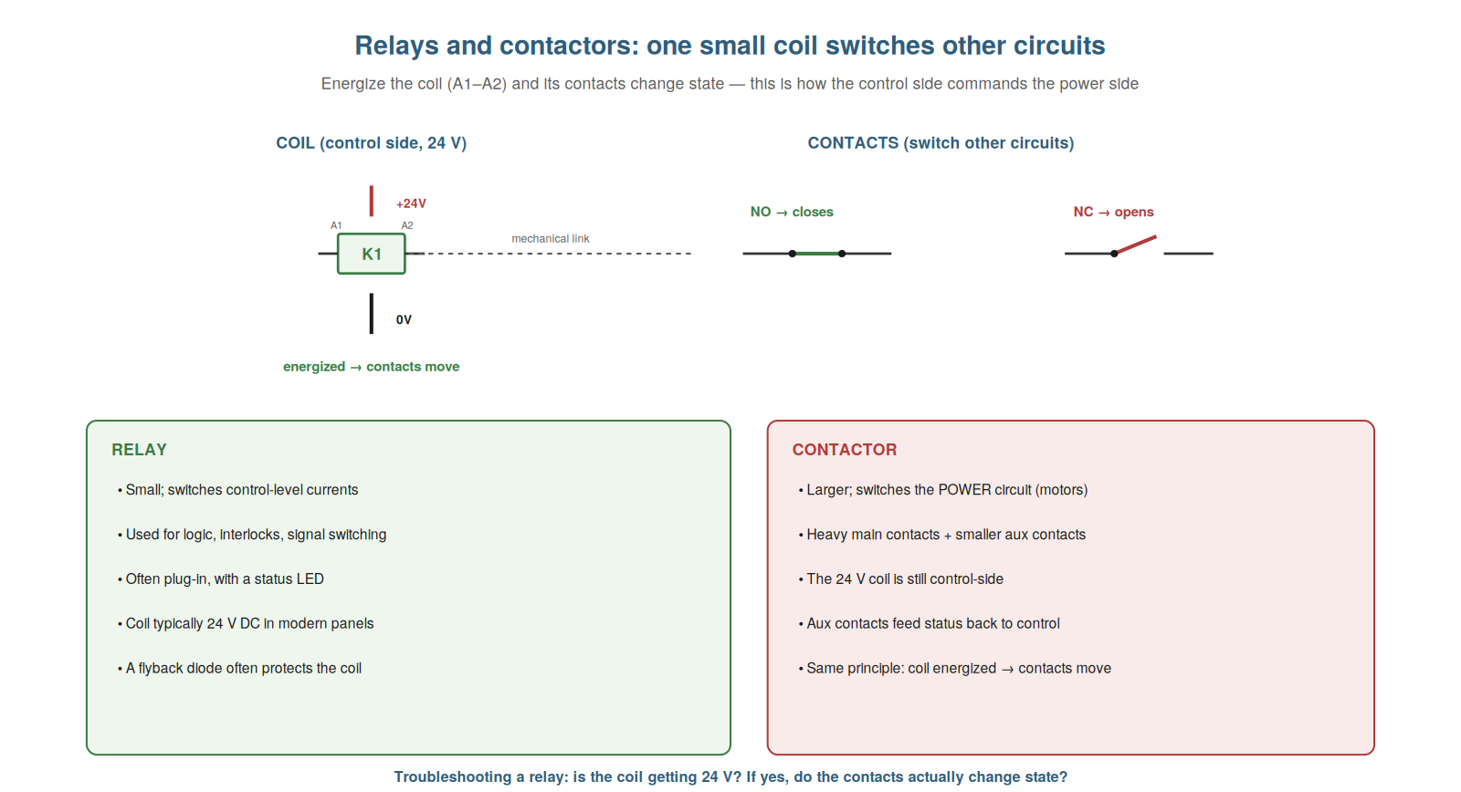
The fundamental operation of a relay or contactor is the coil-and-contacts mechanism, and understanding it is the key to diagnosing them. A relay has a coil (with terminals A1 and A2) and a set of contacts. When the coil is energized — 24 volts applied across A1 and A2 — it becomes an electromagnet and physically moves the contacts: the normally-open contacts close, and the normally-closed contacts open. When the coil is de-energized, the contacts spring back to their resting states. So a small current through the coil switches the contacts, which can carry other circuits. This coil-and-contacts operation is the essence of the relay: the coil is the input (energize it to operate), and the contacts are the output (they switch other circuits). Understanding this two-part operation is the key to troubleshooting a relay, because a relay fault is either the coil not energizing (input problem) or the contacts not switching properly despite the coil energizing (output problem). So understanding coil and contacts frames relay troubleshooting as diagnosing which part has failed. Understanding the coil-and-contacts operation — the coil energizing to move the contacts — is the key to diagnosing relays, dividing faults into coil (input) and contact (output) problems. Understanding the coil and contacts of a relay or contactor — the coil that, when energized with 24 volts, moves the contacts (NO closing, NC opening), and the contacts that switch other circuits — is the key to troubleshooting them, because it divides every relay fault into two clear possibilities: the coil not energizing (an input problem — no 24 volts reaching the coil, or a failed coil) or the contacts not switching properly despite the coil energizing (an output problem — worn, welded, or burnt contacts), which turns relay diagnosis into the simple question of which part, the coil or the contacts, has failed.
Diagnosing a relay
Following from the coil-and-contacts model, understanding how to diagnose a relay gives you a clear two-step method. First, check the coil: measure the voltage across the coil terminals (A1â–A2). Is it getting its 24 volts? If not, the fault is upstream — the circuit feeding the coil is not delivering the voltage (an open in that rung, a control contact not closing), so you trace that. If the coil is getting 24 volts, it should be energized. Second, check the contacts: with the coil energized, do the contacts actually switch as they should? A NO contact should now be closed (passing voltage / having continuity), a NC contact open. If the coil is energized but a contact is not switching — a NO contact still open despite the energized coil — the fault is the contacts (worn, welded, burnt, or a failed relay). So diagnosing a relay is: check the coil voltage (is it energized?), then check the contacts (are they switching?). This two-step method localizes the fault to the coil side or the contact side. Understanding how to diagnose a relay — checking coil voltage then contact switching — gives a clear method localizing the fault. It reinforces that you diagnose a relay by first checking whether the coil gets 24 V, then whether the contacts switch when it does. Understanding how to diagnose a relay — first measuring the coil voltage to see if it is energized (if not, tracing the rung feeding the coil), then checking whether the contacts switch when the coil is energized (if not, suspecting the contacts) — gives you a clear two-step method that localizes the fault to the coil side or the contact side, so that instead of vaguely suspecting the relay, you determine precisely whether the coil is failing to energize (an upstream problem to trace) or the contacts are failing to switch despite an energized coil (the relay’s contacts to address), which is the efficient, targeted way to troubleshoot the relays and contactors that feature in so many control circuits.
Coils, diodes, and common quirks
A few practical quirks of relay coils are worth understanding, because they explain some particular faults and features you will meet. Many DC relay coils have a flyback (freewheeling) diode across them, which suppresses the voltage spike generated when the coil de-energizes, protecting other components; if a relay has a status LED, it often indicates the coil is energized, a handy visual check. A quirk to know: a coil measured out of circuit should have a certain resistance — an open (broken) coil reads infinite resistance and will never energize, a useful test of a suspected failed coil. Another: a relay whose coil is getting marginal voltage (from a voltage drop) may chatter or buzz — pulling in and dropping out rapidly — because the voltage is on the edge of holding it in, a symptom pointing to a supply or voltage-drop problem. And welded contacts (stuck closed from arcing over time) are a contact failure where the relay’s output stays on even when the coil de-energizes. Understanding these quirks — the diode, the LED, the open coil, chattering from marginal voltage, welded contacts — explains particular relay faults and features. Understanding relay coil quirks — the flyback diode, the status LED, the open-coil test, chattering from marginal voltage, and welded contacts — explains particular faults and features you will meet, so that you recognize the diode and LED as normal features, test a suspected failed coil by its resistance (infinite meaning open), diagnose a chattering relay as a marginal-voltage or voltage-drop symptom, and identify welded contacts as a contact failure leaving the output stuck on, which rounds out your practical understanding of the relays and contactors beyond the basic coil-and-contacts model to include the quirks that explain their particular real-world faults.
The seal-in (latching) circuit
A classic and important relay circuit worth understanding is the seal-in (or latch), because it appears constantly in control circuits and explains a common behavior. In a seal-in circuit, a relay, once energized by a momentary start button, keeps itself energized through one of its own contacts wired in parallel with the start button: pressing start energizes the coil, the coil closes its seal-in contact, and that contact now provides the current even after the start button is released — the relay ‘seals itself in’. A normally-closed stop button in the circuit breaks it to drop the relay out. So the seal-in makes a momentary press give continuous operation until stopped, which is how most start/stop circuits work. Understanding this explains the behavior (why a machine keeps running after you release start) and helps troubleshoot it (a seal-in contact that fails means the machine stops when you release start; a stop button open means it will not start). So understanding the seal-in circuit — a relay holding itself in through its own contact — explains and helps troubleshoot the common start/stop circuit. Understanding the seal-in (latching) circuit — a relay keeping itself energized through its own contact wired parallel to the start button, so a momentary press gives continuous operation until a stop button drops it out — explains a circuit that appears constantly, so that you understand why a machine keeps running after you release the start button and can troubleshoot the circuit (a failed seal-in contact causing the machine to stop when start is released, or an open stop button preventing starting), which is essential because the seal-in is the basis of most start/stop control and recognizing it lets you diagnose the very common faults that involve it.
Scenario: coil good, contacts bad
A scenario shows the two-step relay diagnosis localizing a fault to the contacts. A relay was suspected because its downstream circuit was dead, and the technician applied the two-step method. First, the coil: he measured across the coil terminals and found a solid 24 volts — the coil was energized, so that was not the problem. Second, the contacts: with the coil energized, he checked whether the relay’s normally-open contact had closed to feed the downstream circuit — and it had not; measuring across it showed it was still open despite the energized coil. So the fault was the contacts, not the coil: the contact had failed to close (worn or burnt). He replaced the relay, and the downstream circuit came alive. The two-step method — coil good, contacts bad — had localized the fault precisely. This scenario shows the two-step relay diagnosis localizing the fault to the contacts. Understanding the coil-then-contacts method let the technician confirm the coil was energized and find the contacts failing to switch. It reinforces that checking coil voltage then contact switching localizes a relay fault to the coil or contact side. The scenario reinforces the two-step relay diagnosis: whe technician localized a fault to the relay’s contacts by confirming the coil was energized (24 volts across it) but the contacts were not switching (still open despite the energized coil), illustrating how the method of checking the coil then the contacts pinpoints whether a relay fault is the coil not energizing or the contacts not switching, here cleanly identifying failed contacts on an energized coil.
Auxiliary contacts and feedback
A useful concept is the auxiliary contact and its role in feedback, because understanding it explains how the control circuit knows what a contactor is doing and how some faults are detected. Besides its main contacts (which switch the power), a contactor usually has auxiliary contacts — smaller contacts that operate with the main ones — used by the control circuit for feedback and interlocking. An auxiliary contact can feed a signal back to the control side or PLC indicating the contactor’s state (pulled in or not), so the control system knows whether the contactor actually operated. This feedback enables fault detection: if the control commands the contactor on but the auxiliary contact does not confirm it pulled in, the control system knows something is wrong (the contactor failed to operate). Understanding auxiliary contacts and feedback explains this monitoring: the aux contact is how the control circuit senses the contactor’s actual state, and a mismatch between commanded and confirmed indicates a fault. So understanding auxiliary contacts and feedback explains how contactor operation is monitored and faults detected. Understanding auxiliary contacts and feedback — the smaller contacts that operate with the main ones to feed the contactor’s actual state back to the control circuit — explains how the control system knows whether a contactor operated and detects when it did not, so that you understand the feedback role of auxiliary contacts (confirming the contactor pulled in) and how a mismatch between the commanded and confirmed state signals a fault, which explains both a common monitoring arrangement and a class of faults where the feedback reveals a contactor that failed to operate as commanded, an important part of understanding contactors in real control systems.
Coil then contacts as your routine
To close, it is worth crystallizing the routine this chapter builds for relays: always check the coil, then the contacts, because this routine reliably localizes any relay fault. Faced with a suspected relay, the routine is: first, is the coil getting its 24 volts (is it energized)? Then, if energized, are the contacts actually switching? This two-part routine splits every relay fault cleanly into a coil-side problem (not energizing) or a contact-side problem (not switching despite the coil), directing you to the right half every time. Making this your routine — coil then contacts — turns relay troubleshooting from vague suspicion into a reliable two-step localization. So the coil-then-contacts routine is how you reliably diagnose any relay. Understanding coil-then-contacts as your routine — always checking the coil then the contacts — reliably localizes any relay fault. Understanding coil then contacts as your routine — always checking first whether the coil is energized and then whether the contacts switch — reliably localizes any relay fault, so that you approach every suspected relay with the two-step routine that splits the fault cleanly into a coil-side problem (not energizing) or a contact-side problem (not switching despite an energized coil), which turns relay troubleshooting from vague suspicion into a dependable localization and is the practical routine that flows from understanding the coil-and-contacts operation of relays and contactors.