Relays are one of the most important components in industrial automation and electrical control circuits.
They are used to switch electrical circuits on and off. In many machines, relays and contactors are used to control motors, lamps, heaters, solenoid valves, and other electrical loads.
In simple words:
A relay is an electrically operated switch.
Instead of switching a load by hand, we can use a small control signal to switch a bigger circuit.
Why Relays Are Important
Relays are important because they allow a control circuit to operate a power circuit.
For example, a small control switch or PLC output can energize a relay coil. The relay then closes its contacts and allows current to flow to a motor or other load.
This is very useful because the control circuit and the power circuit can be separated.
A relay can allow a low-current control circuit to switch a higher-current load.
That is one of the main reasons relays are used so much in automation.
Relay vs Contactor
The words relay and contactor are sometimes used in a similar way.
Both are electrically operated switches.
The main difference is usually the size and application.
A relay is often used for smaller control circuits or lower-power loads.
A contactor is usually used for larger loads, especially electric motors.
For example:
A relay may switch a signal lamp, small solenoid, or control signal.
A contactor may switch a three-phase motor.
The operating principle is very similar. Both use a coil and contacts.
Relay as a Binary Actuator
A relay can be called a binary actuator because it has two main states:
ON — energized
OFF — de-energized
When the relay coil is energized, the contacts change state.
When the relay coil is de-energized, the contacts return to their normal state.
This is different from a servomotor, which can move continuously through many positions. A relay is much simpler. It is either on or off.
That makes relays very useful in logic control circuits.
Basic Parts of a Relay
A simple electromechanical relay has several main parts:
Coil
Iron core
Movable armature
Electrical contacts
Return spring
Terminals
Insulation parts
Let’s look at what each part does.
Relay Coil
The coil is the control part of the relay.
When voltage is applied to the coil, current flows through it and creates a magnetic field.
This magnetic field pulls the movable armature.
The coil can be designed for different voltages, such as:
24 V AC
24 V DC
110 V AC
230 V AC
Other standard control voltages
The coil voltage must match the control circuit voltage. If the wrong voltage is used, the relay may not work correctly or may be damaged.
Core and Armature
The core helps concentrate the magnetic field created by the coil.
The movable armature is the part that moves when the coil is energized.
When the magnetic field becomes strong enough, it pulls the armature toward the core.
This movement is what opens or closes the relay contacts.
Relay Contacts
Relay contacts are the switching part of the relay.
They are conductive metal pieces that open or close an electrical circuit.
When the contacts touch, current can flow.
When the contacts separate, current stops.
Contacts can be used to switch loads such as:
Motors
Solenoid valves
Signal lamps
Heaters
Control circuits
Alarm circuits
Auxiliary circuits
The contact current rating is very important. A small relay contact cannot safely switch a large motor current.
Return Spring
The return spring brings the relay back to its normal position when the coil is de-energized.
When the coil loses power, the magnetic field disappears. The spring then pulls the movable armature back.
This opens or closes the contacts depending on the contact type.
How a Relay Works
A relay works by using a small control current to control a separate electrical circuit.
There are usually two circuits involved:
Control circuit
Power circuit
The control circuit energizes the relay coil.
The power circuit supplies power to the load.
These two circuits are electrically separated inside the relay.
Simple Relay Example
Imagine we want to control a motor using a relay.
The motor is connected to the relay contacts in the power circuit.
The relay coil is connected to a control switch in the control circuit.
When the control switch is pressed, voltage is applied to the relay coil.
The coil creates a magnetic field.
The magnetic field pulls the movable armature.
The relay contacts close.
Current flows through the power circuit.
The motor starts.
When the control switch is opened, the relay coil loses power.
The magnetic field disappears.
The return spring moves the armature back.
The contacts open.
The motor stops.
That is the basic operation of a relay.
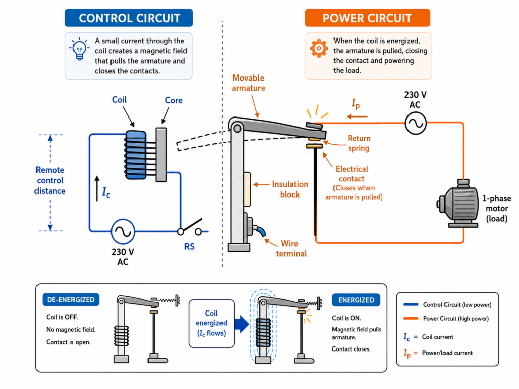
Control Circuit and Power Circuit
One of the most important ideas in relay control is the difference between the control circuit and the power circuit.
Control Circuit
The control circuit is the low-power side.
It usually contains:
Push buttons
Selector switches
PLC outputs
Relay coils
Sensors
Control voltage supply
This circuit decides when the relay should turn on or off.
The current in the control circuit is usually small.
Power Circuit
The power circuit is the load side.
It usually contains:
Main power supply
Relay or contactor contacts
Motor
Heater
Solenoid
Other electrical load
The current in the power circuit can be much higher than in the control circuit.
This is why the relay or contactor must be sized correctly for the load.
Relay ON and OFF States
A relay has two basic operating states.
Relay Energized
The relay is energized when voltage is applied to the coil.
In this state:
The coil creates a magnetic field
The armature moves
The contacts change state
The load may turn on
This can be thought of as relay state ON or logic 1.
Relay De-Energized
The relay is de-energized when voltage is removed from the coil.
In this state:
The magnetic field disappears
The return spring moves the armature back
The contacts return to normal
The load may turn off
This can be thought of as relay state OFF or logic 0.
This ON/OFF behavior is why relays are useful in automation logic.
Normally Open and Normally Closed Contacts
Relay contacts can be normally open or normally closed.
Normally Open Contact
A normally open contact is open when the relay coil is not energized.
When the coil is energized, the contact closes.
This type of contact is often used to turn something on.
Example:
Press start button → relay energizes → contact closes → motor starts.
Normally Closed Contact
A normally closed contact is closed when the relay coil is not energized.
When the coil is energized, the contact opens.
This type of contact is often used for stop circuits, interlocks, alarms, or safety-related logic.
Example:
Relay energizes → normally closed contact opens → another circuit is interrupted.
Power Relays and Control Relays
From a practical point of view, relays can be grouped into two common categories:
Power relays
Control relays
Power Relays
Power relays are used to switch higher currents.
They can control larger loads such as motors, heaters, or other power devices.
Contactors are a common example of power switching devices used for motors.
The size of the relay or contactor depends mainly on the current that its contacts must switch.
Control Relays
Control relays are used in control circuits.
They usually switch smaller currents and are often used for logic, interlocking, signal switching, and auxiliary control.
For example, a control relay can be used to create a holding circuit, enable another relay, or send a signal to a PLC input.
Common Relay Coil Voltages
Relay coils are available in different standard voltage ratings.
Common AC coil voltages include:
24 V AC
48 V AC
110 V AC
230 V AC
380 V AC
Common DC coil voltages include:
12 V DC
24 V DC
48 V DC
110 V DC
230 V DC
In modern industrial control panels, 24 V DC is very common for control circuits.
Older systems or certain machines may use 110 V AC or 230 V AC control circuits.
Always check the relay coil rating before wiring it.
Relay Current Ratings
A relay has two important electrical ratings:
Coil voltage rating
Contact current rating
The coil voltage rating tells you what voltage should be used to energize the relay.
The contact current rating tells you how much current the relay contacts can safely switch.
For example, a relay coil may be 24 V DC, but the contacts may be rated for 10 A at 230 V AC.
These are separate things.
Do not confuse the coil voltage with the contact rating.
Why Relays Can Be Controlled Remotely
A relay can be controlled from a distance because the control switch does not need to carry the full load current.
For example, a push button can be installed on a machine operator panel, while the relay or contactor is inside the electrical cabinet.
The push button only energizes the relay coil.
The relay contacts switch the motor power.
This makes control safer and more practical.
However, long control wires can cause voltage drop. If the voltage drop is too large, the relay coil may not energize properly.
This is why wire size, distance, coil voltage, and AC/DC supply type matter in control circuit design.
Relay Switching Time
Electromechanical relays are not instant.
They need a small amount of time to switch.
Typical operating times may be in the range of milliseconds.
For many industrial control circuits, this is fast enough.
However, for very high-speed switching, electronic devices such as solid-state relays may be better.
Electromechanical Relays vs Solid-State Relays
There are two major relay types:
Electromechanical relays
Solid-state relays
Electromechanical Relays
Electromechanical relays use a coil, magnetic field, moving armature, spring, and mechanical contacts.
Advantages:
Simple
Easy to understand
Provides electrical isolation
Can switch AC or DC depending on contact rating
Useful in many control circuits
Disadvantages:
Mechanical wear
Contact arcing
Slower switching
Audible clicking sound
Limited switching life
Solid-State Relays
Solid-state relays do not have moving mechanical contacts.
They use electronic components such as transistors, thyristors, or triacs to switch the load.
Advantages:
No mechanical wear
Silent operation
Fast switching
Good for frequent switching
Disadvantages:
Can generate heat
May need a heat sink
Can leak small current when off
Must be selected carefully for AC or DC loads
Usually fails differently than mechanical relays
Both types are useful, but they are used in different situations.
Simple Relay Example in Automation
Let’s say a conveyor motor must start when a start button is pressed.
The control circuit works like this:
Operator presses the start button.
The relay coil energizes.
The relay contact closes.
The motor contactor energizes.
The motor starts.
When the stop button is pressed, the relay coil de-energizes.
The contact opens.
The contactor drops out.
The motor stops.
This is a basic automation sequence, but the same idea is used in many machines.
More complex machines simply use more relays, sensors, interlocks, timers, and PLC logic.
Final Thoughts
Relays are basic but very important components in industrial automation.
They allow a control circuit to switch another electrical circuit. This makes it possible to control motors, lamps, valves, heaters, and many other devices.
A relay works by energizing a coil, creating a magnetic field, moving an armature, and changing the state of electrical contacts.
The key ideas to remember are:
A relay is an electrically operated switch.
It has a coil and contacts.
The coil belongs to the control circuit.
The contacts switch the power circuit.
The relay has two main states: ON and OFF.
Relays are useful for control logic and automation circuits.
Contactors are similar to relays but are usually used for larger motor loads.
For anyone learning PLCs, motor control, or industrial automation, understanding relays is essential.
They are one of the building blocks of real machine control.