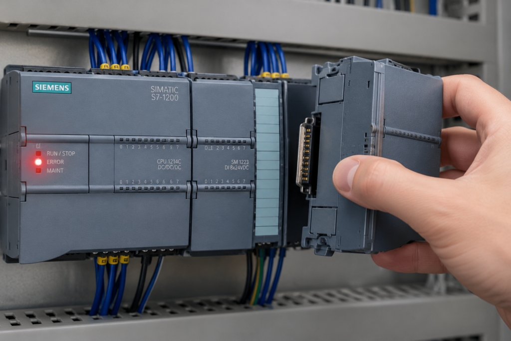
The new module clicks into place. Power comes back on. You expect the red fault light to disappear.
It doesn’t.
At this point, the natural reaction is to suspect the replacement module. Perhaps it is defective too. Perhaps stores somehow keep a special shelf full of broken Siemens parts specifically for Friday-afternoon maintenance jobs.
Usually, though, the new module is fine.
Replacing an I/O module only clears the fault when the original module was actually the source of the problem and the replacement matches the PLC configuration. A wrong order number, incorrect slot, missing hardware download or unresolved wiring fault can leave the station in exactly the same condition as before.
The key is to stop swapping parts and check what the PLC is really complaining about.
Start With the Exact Diagnostic Message
A red LED tells you that something is wrong. It does not tell you what.
Before removing another module, open TIA Portal and examine the affected station:
- Go online with the PLC.
- Open Devices & networks or the device configuration.
- Select the affected CPU, interface module or I/O module.
- Open Online & diagnostics.
- Check the diagnostic status and diagnostic buffer.
- Compare the configured hardware with the detected online hardware.
TIA Portal can display differences between the configured module and the physically installed module. Where available, it also shows the article number of both the configured and actual device. That little comparison is often more useful than staring at blinking LEDs for twenty minutes.
Pay attention to wording such as:
- Wrong module
- Module configured but not available
- Module or submodule mismatch
- IO device not reachable
- Channel fault
- Wire break
- Short circuit
- Missing load voltage
- Parameter assignment error
- Configuration differs from actual hardware
- Device name does not match
“Module fault” and “channel fault” are not the same thing. That distinction matters enormously.
1. The Replacement Has the Wrong Order Number
Two Siemens modules can look almost identical while being completely different as far as the PLC is concerned.
The front connector fits. The number of channels looks right. Both modules may even say “DI 16x24VDC” on the front. Still, one character near the end of the article number can represent a different module type, output technology, channel grouping, diagnostic capability or hardware generation.
For example, a replacement may have:
- A different number of channels
- Different input or output addresses
- Different electrical characteristics
- Source outputs instead of relay outputs
- Standard channels instead of high-feature channels
- Different diagnostic functions
- Different supported parameter settings
- A different BaseUnit requirement
- Standard functionality instead of fail-safe functionality
- A different article-number suffix
TIA Portal compares the actual module with the one stored in the hardware configuration. A physically compatible module is not automatically a configuration-compatible module.
Siemens’ hardware replacement procedure only offers components that support replacement and are considered compatible. After changing a configured hardware component, Siemens instructs users to compile the hardware and software.
What to check
Read the full Siemens article number from the side or front of the original and replacement modules.
Do not compare only the first few digits.
A typical article number may look like this:
6ES7 131-6BH01-0BA0
Every section matters. Check:
- Product family
- Module type
- Channel version
- Feature level
- Hardware variant
- Final suffix
Then compare that number with the module configured in TIA Portal.
In the device view, select the module and check its article number in the properties or hardware catalog. When online, compare the configured type with the actual detected type.
Can a newer module replace an older one?
Sometimes, yes. But “newer” does not always mean “drop-in compatible.”
A newer hardware version might be fully backward-compatible. Another replacement may require:
- A different hardware-catalog entry
- A newer TIA Portal version
- Updated hardware-support packages
- Changed parameter settings
- A firmware update
- Modification of the device configuration
- A fresh hardware download
Do not assume compatibility because the module physically fits. Let the hardware catalog and Siemens compatibility information make that decision.
2. The Module Is Installed in the Wrong Position
This one is painfully easy to do, particularly in a crowded ET 200SP station containing several similar modules.
Suppose the configured station contains:
- Slot 1: Digital input module
- Slot 2: Digital input module
- Slot 3: Digital output module
- Slot 4: Analog input module
If the replacement digital output module is accidentally placed in slot 2 rather than slot 3, the PLC now sees two problems:
- The module expected in slot 2 is missing or wrong.
- The module expected in slot 3 is still missing.
The new module may be perfectly healthy. It is simply standing in the wrong queue.
Siemens diagnostics can identify missing modules, additional modules and modules installed in the wrong slot. Depending on the station and its startup settings, the device may continue operating with faults or may refuse to complete startup.
Check the complete station order
Count slots from the interface module according to the rules for that I/O system. Do not count by eye from whichever end of the rail is most convenient.
Check:
- The slot number shown in TIA Portal
- The order of all physical modules
- Empty slots or server modules
- BaseUnit arrangement
- Potential modules or placeholders
- Expansion-rack numbering
- Submodule positions in modular devices
With S7-300 systems, physical slot rules also matter. Certain positions are reserved for the power supply, CPU or interface module, and signal modules must follow the permitted rack arrangement.
Watch out for shifted modules
Sometimes the replacement itself is in the “right” relative position, but another module was previously removed or inserted incorrectly. Every module after that point is now shifted by one slot.
The quickest check is to compare the entire physical station from left to right against the TIA Portal device view.
Take a photograph. Zoom in. Read every label.
It sounds basic, but basic catches a surprising number of faults.
3. The Hardware or Firmware Revision Is Different
The article number may match while the module revision does not.
Siemens hardware can be released in different:
- Hardware versions
- Firmware versions
- Functional states
- Product revisions
A replacement from newer stock may contain firmware that did not exist when the original project was created. An old spare taken from another cabinet may be several revisions behind.
Many revision differences are compatible. Some are not, particularly when the project expects a certain feature, parameter or firmware level.
TIA Portal’s online diagnostics can display information such as the module firmware version, hardware version and serial number for supported devices.
Possible symptoms of a revision mismatch
You may see:
- Module present but not operational
- Parameter assignment fault
- Configured and actual module mismatch
- Firmware version not supported
- Unsupported function
- Module rejected during startup
- Channel parameters not accepted
- Safety-module passivation
- Device visible online but not exchanging cyclic data
What to do
First, record the firmware and hardware versions of the replacement.
Then check:
- Whether the version is supported by the current project.
- Whether the exact module is available in the installed TIA Portal hardware catalog.
- Whether a hardware-support package is required.
- Whether the module can be configured using an older compatible firmware version.
- Whether the project should be updated to match the installed hardware.
- Whether a Siemens-approved firmware update or downgrade is supported.
Do not perform random firmware changes in the hope that one will stick. That can turn a manageable configuration problem into a module that no longer starts correctly.
For fail-safe I/O, revision changes deserve even more care. Any change affecting safety hardware, PROFIsafe addresses or safety parameters may require validation and an updated safety acceptance procedure.
4. The Hardware Configuration Was Not Downloaded
Replacing a module physically does not automatically update the PLC project.
If the new module differs from the configured one—even if it is a valid substitute—you may need to modify the device configuration, compile it and download the new hardware configuration to the CPU.
A common sequence looks like this:
- The original module fails.
- Maintenance installs the closest available spare.
- An engineer updates the module in the offline TIA Portal project.
- The engineer saves the project.
- Everyone wonders why the PLC still reports the old mismatch.
Saving is not downloading.
The CPU continues using the configuration already stored in its memory until the changed hardware configuration is transferred to it.
Correct procedure after changing the configured module
Where the machine design and change procedures allow it:
- Replace the module in the TIA Portal device configuration.
- Review all module parameters.
- Check I/O addresses.
- Check channel assignments and tag mappings.
- Compile the hardware configuration.
- Resolve compilation errors and warnings.
- Download the hardware configuration to the correct CPU.
- Restart the station if required.
- Go online again and compare offline and online hardware.
- Test every affected signal.
When replacing a configured hardware component in STEP 7, Siemens specifies that the selected devices must be compatible and that the hardware and software should be compiled after the replacement.
Be careful with address changes
Replacing one module type with another can change:
- Input addresses
- Output addresses
- Process-image allocation
- Diagnostic addresses
- Channel layout
- Data-record structure
- HMI tag references
- Safety addresses
- Program references
The hardware fault may disappear while the machine develops a completely new problem because the program is now reading the wrong bytes.
Always compare addresses before downloading.
5. The PROFINET Device Name Was Not Assigned
This cause applies especially when the “module” being replaced is actually:
- An ET 200 interface module
- A complete distributed I/O station
- A PROFINET coupler
- A drive
- A valve terminal
- A remote I/O block
- Another PROFINET IO device
PROFINET does not identify an IO device using its IP address alone. The IO controller uses the configured PROFINET device name to identify and commission the device.
A new PROFINET device normally arrives without the plant-specific device name stored in the old unit. Siemens documentation states that a PROFINET IO device in its delivery state has no assigned device name and must receive one before the IO controller can address it.
So the new interface module may power up, appear under accessible devices and even show a sensible IP address, yet remain disconnected from the CPU because its name is wrong or blank.
Typical symptoms
- BF LED flashing
- PROFINET device not reachable
- IO device failure
- Device visible in TIA Portal but not assigned to the controller
- Correct IP address but no cyclic communication
- Station name mismatch
- All I/O modules behind the interface module shown as faulty
- Red crosses over the entire remote station
How to assign the PROFINET name
In TIA Portal:
- Connect the programming computer to the PROFINET network.
- Select the correct network adapter under the PG/PC interface.
- Open Online access or Accessible devices.
- Identify the replacement device by MAC address.
- Use Assign PROFINET device name.
- Select the exact name configured in the project.
- Use the flash-LED function, where supported, to confirm that you selected the correct physical device.
- Assign the name.
- Allow the device to restart or power-cycle it if required.
Siemens’ current STEP 7 instructions specifically recommend the LED flash test as a way of verifying that the intended IO device has been selected before assigning its name.
Spelling matters.
et200sp-line-1 and et200sp_line_1 are not the same name. In fact, the second may not even satisfy PROFINET naming rules.
Automatic device replacement
Some Siemens systems support device replacement without manually assigning the name, provided the PROFINET topology has been configured correctly and the required controller and device functions are supported.
In these arrangements, the IO controller can identify the replacement by its physical network position and assign the appropriate device name. Siemens documents this as device replacement without an exchangeable medium.
Useful feature. Not magic.
It depends on correct topology configuration, supported hardware and unchanged network connections. Moving cables between switch ports can prevent the automatic replacement from working as expected.
Some interface modules also store the device name on removable media. On supported ET 200M equipment, for example, transferring the memory card from the old interface module can transfer the PROFINET device name to the replacement.
6. The Channel Fault Still Exists in the Field Wiring
Here is the big one.
The module was never the problem.
An I/O module may report a fault because it has detected an electrical problem outside the module. Replacing it does nothing because the same damaged cable, failed sensor or short circuit is immediately connected to the new hardware.
The new module powers up, checks its channels and reports the exact same fault. Quite reasonably, really.
Common digital-input field faults
- Broken sensor cable
- Missing 24 V supply
- Missing 0 V reference
- Loose terminal
- Defective proximity sensor
- Incorrect PNP or NPN sensor type
- Sensor wired to the wrong channel
- Short circuit between signal and 0 V
- Short circuit between signal and 24 V
- Faulty terminal block
- Damaged connector
- Channel diagnostics configured for a circuit that does not support them
Common digital-output field faults
- Shorted solenoid coil
- Short circuit in the output cable
- Reversed polarity
- Excessive output current
- Missing load voltage
- Missing output-group supply
- Incorrect common connection
- Damaged relay or contactor coil
- Suppression diode connected backwards
- Output load exceeding the channel rating
- Several loads incorrectly connected to one output
Common analog-input faults
- Open 4–20 mA loop
- Two-wire transmitter not powered
- Incorrect current or voltage configuration
- Wrong terminal connection
- Reversed current-loop polarity
- Broken shield or reference conductor
- Input outside the configured range
- Incorrect sensor type
- RTD connected with the wrong two-, three- or four-wire arrangement
- Channel configured for 4–20 mA while receiving 0–10 V
Common analog-output faults
- Open current loop
- Excessive load resistance
- Short circuit
- Incorrect voltage/current mode
- Missing actuator supply
- Incorrect common connection
- Damaged valve positioner or drive input
- Faulty isolator or signal conditioner
A channel-specific diagnostic is evidence that the module can see a problem associated with that channel. It is not proof that the module itself has failed.
Isolate the Field Wiring Before Replacing Another Module
When permitted by the equipment design and safety procedures, disconnect the field connector or affected channel wiring from the replacement module.
Then check whether the diagnostic changes.
- If the module fault disappears and a predictable open-circuit diagnostic appears, the field wiring or load is suspicious.
- If the same internal module fault remains with the field wiring removed, the problem may be in the module, BaseUnit, backplane or configuration.
- If the fault moves when channels are swapped, the connected field circuit is probably responsible.
- If the fault remains on the same physical channel with known-good wiring, the module channel or terminal assembly becomes more suspicious.
Do not move field wires carelessly on an operating machine. Outputs can start equipment, release pressure, energize heaters or move actuators. Follow lockout procedures and verify the machine’s safe state first.
Check the BaseUnit, Terminal Block and Backplane
With ET 200SP, the plug-in I/O module is only part of the channel.
The BaseUnit provides terminal connections, potential-group distribution and module coding. A replacement I/O module will not repair:
- A damaged BaseUnit
- Burned terminal contacts
- Bent backplane contacts
- Incorrect BaseUnit type
- Broken potential-group connection
- Missing supply bridge
- Loose push-in terminal
- Incorrect AUX-bus arrangement
- Damaged server module
- Backplane-bus interruption
This can be confusing because the removable module is the obvious part, while the less glamorous BaseUnit stays behind and quietly keeps the fault alive.
Inspect for:
- Heat discoloration
- Melted plastic
- Bent or recessed contacts
- Loose conductors
- Incorrect terminal numbering
- Wrong BaseUnit colour or type
- Missing 24 V or 0 V at the potential group
- Contamination or conductive debris
Measure the supply voltage at the module terminals under load. A multimeter reading of 24 V with the load disconnected may collapse as soon as the output attempts to energize.
The Fault May Need Acknowledgement or Reintegration
After correcting the physical problem, certain faults do not disappear merely because the wire is repaired.
Depending on the module and application, you may need to:
- Acknowledge the alarm
- Reset a diagnostic latch
- Restart the I/O device
- Power-cycle the station
- Clear a user-program fault flag
- Re-enable the channel
- Reintegrate a passivated fail-safe module
- Reset a drive or intelligent field device
- Return the machine to a valid operating state
This is particularly important with fail-safe I/O.
A safety channel may remain passivated after the external fault is removed. The safety program must confirm that reintegration conditions are met, and the machine’s safety-validation procedures must be followed. Do not force or bypass an F-I/O channel simply to make the red light go away.
A Practical Troubleshooting Sequence
Random replacement becomes expensive rather quickly. Use a consistent order instead.
Step 1: Read the diagnostic buffer
Write down the exact fault text, timestamp, slot and channel number.
Do not summarize it as “I/O bad.” Those two words throw away most of the useful information.
Step 2: Compare configured and actual hardware
Check:
- Full article number
- Hardware version
- Firmware version
- Rack or station
- Slot
- Subslot
- Module parameters
TIA Portal can show differences between the configured and physically detected module, including set and actual article numbers where supported.
Step 3: Confirm the physical position
Compare the entire rack with the project from left to right.
Check the interface module, every I/O module, empty positions, BaseUnits and server module.
Step 4: Verify the hardware download
Check whether the online configuration matches the offline project.
If configuration changes were made, compile and download them according to the machine’s change-control procedure.
Step 5: Check PROFINET identity
For a replaced remote-I/O interface, verify:
- PROFINET device name
- IP address
- MAC address
- Network cable
- Switch port
- Configured topology
- Device assignment to the correct IO controller
Step 6: Separate module faults from channel faults
A wrong-module message points toward hardware configuration.
A wire-break, short-circuit or missing-load-voltage message points toward the external circuit or supply.
Do not treat them as the same category.
Step 7: Test field voltage and continuity
Measure the affected circuit rather than merely looking at it.
Check:
- 24 V supply
- 0 V reference
- Potential-group voltage
- Sensor output
- Load resistance
- Cable continuity
- Short circuit to ground or supply
- Current-loop value
- Connector pinout
Step 8: Inspect the terminal system
Check the front connector, BaseUnit, backplane contact and terminal tightness.
A perfectly good module cannot communicate through a bent contact or power a load through a burned terminal.
Step 9: Clear or acknowledge the remaining diagnostic
After correcting the root cause, perform the appropriate reset, reintegration or restart.
Step 10: Test every affected channel
Do not stop when the red LED turns off.
Force or manually operate signals only when permitted and safe. Confirm the PLC input status, physical output voltage, field-device response, HMI indication and machine interlocks.
Quick Fault Interpretation
“Wrong module” or “Configured module differs from actual module”
Most likely causes:
- Wrong article number
- Wrong slot
- Incompatible hardware revision
- Hardware configuration not downloaded
- Incorrect offline project
“Module configured but not available”
Most likely causes:
- Module missing
- Backplane connection problem
- Remote station offline
- Interface-module failure
- Missing station power
- Wrong PROFINET name
“IO device not reachable”
Most likely causes:
- Wrong or missing PROFINET name
- Network cable disconnected
- Device has no power
- Wrong network interface selected
- Switch or port problem
- Duplicate IP address
- Incorrect topology
“Wire break”
Most likely causes:
- Open sensor circuit
- Disconnected conductor
- Failed transmitter
- Incorrect channel configuration
- Load current below the diagnostic threshold
“Short circuit” or “Overload”
Most likely causes:
- Damaged field cable
- Shorted solenoid
- Incorrect wiring
- Output load too large
- Reversed suppression diode
- Defective actuator
“Missing load voltage”
Most likely causes:
- Output-group supply missing
- Blown fuse
- Loose potential-group jumper
- BaseUnit supply problem
- Emergency-stop circuit removed actuator power
- Separate load supply switched off
Do Not Assume the Spare Is Correct
A spare part with a handwritten label saying “ET200 input” is not enough.
For critical machinery, record the complete approved spare-part information:
- Siemens article number
- Permitted substitute numbers
- Minimum or approved firmware
- Required BaseUnit
- Slot location
- Module parameters
- Safety classification
- PROFIsafe address requirements
- Replacement instructions
- Whether a hardware download is required
That turns a breakdown into a controlled replacement instead of an archaeological dig through old electrical cabinets.
The Important Lesson
A replaced I/O module does not automatically clear a Siemens PLC fault because the PLC is not simply checking whether a shiny new piece of plastic has appeared on the rail.
It checks identity. Position. Configuration. Communication. Channel health.
And the field circuit is still there, exactly as it was before.
When the fault remains, begin with the diagnostic text. Confirm the complete article number, verify the slot, compare hardware revisions, download the correct configuration and assign the PROFINET name where necessary. Then test the wiring and load attached to the reported channel.
Quite often, the second module is innocent.
The broken sensor cable hiding under the conveyor? Not so much.