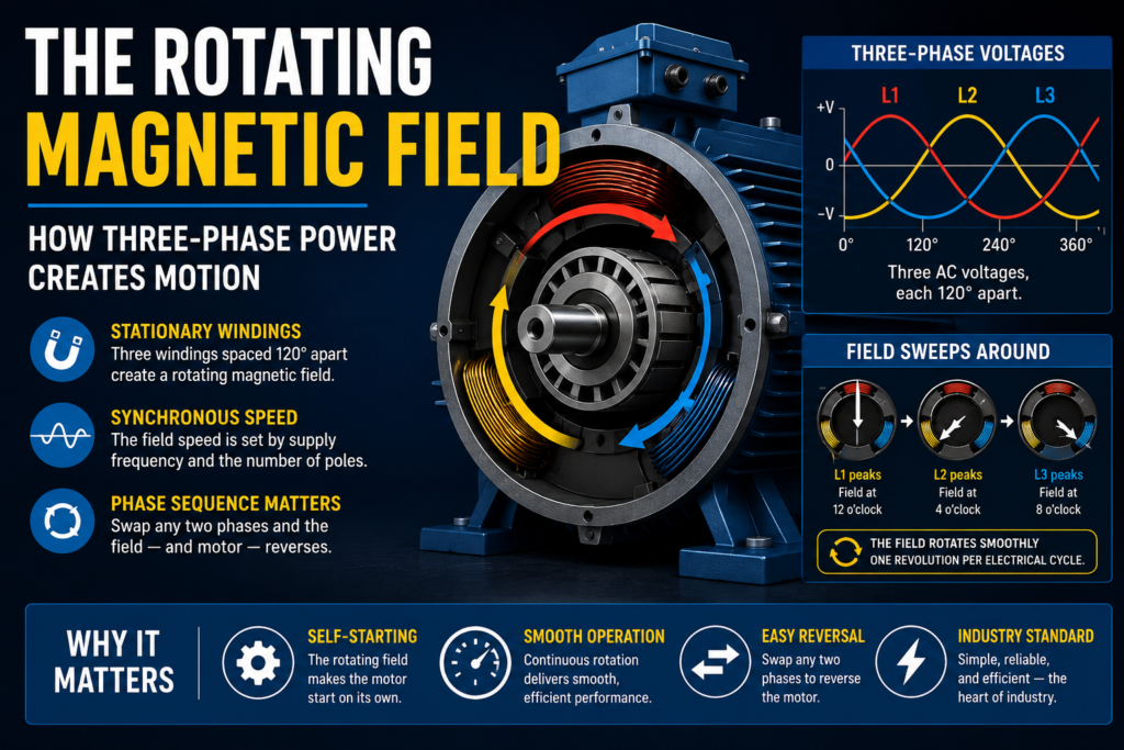
The rotating magnetic field is the central idea of the three-phase induction motor — the mechanism by which stationary windings, fed by three-phase power, create a magnetic field that sweeps around the motor and drags the rotor with it. Understanding how this field arises, and why it rotates, is understanding the heart of the motor, and it explains much of the motor’s behavior including how it starts, how fast it runs, and what happens when something goes wrong with the supply.
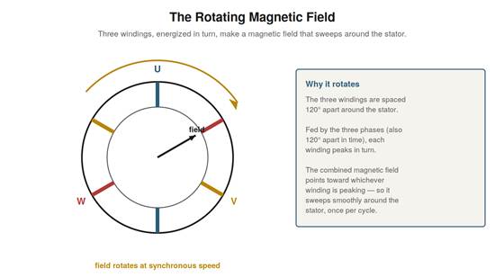
Figure 2.1 — The rotating magnetic field. Three windings spaced 120° apart, fed by the three phases (also 120° apart in time), each peak in turn, so the combined magnetic field sweeps smoothly around the stator.
How stationary windings make a rotating field
The rotating field arises from the combination of two things: three windings spaced 120 degrees apart around the motor’s stator, and the three-phase voltages, also 120 degrees apart in time, that feed them. Each winding, when its phase is at a peak, produces a strong magnetic field pointing in its direction. Because the three phases peak in turn, the three windings produce their strongest fields in turn, and the combined magnetic field points toward whichever winding is currently peaking. As the phases cycle — first one winding peaking, then the next, then the next — the combined field points first toward one winding, then the next, then the next, sweeping around the stator. The result is a magnetic field that rotates smoothly around the motor, created entirely by the stationary windings and the timed three-phase voltages, with nothing physically moving. This is the elegant core of the motor: the spatial arrangement of the windings (120 degrees apart) combined with the temporal arrangement of the phases (120 degrees apart) produces a rotating field from stationary parts, and it is this rotating field that will turn the rotor.
Synchronous speed
The rotating field turns at a definite speed, called the synchronous speed, set by the supply frequency and the number of magnetic poles the windings form. The field completes one rotation in step with the cycling of the phases, so a higher supply frequency means a faster-rotating field, and more poles (more winding groups around the stator) means a slower rotation for a given frequency, because the field has more positions to step through per cycle. The synchronous speed is thus determined by the frequency and the pole count, and it is a fixed speed for a given motor on a given supply. This synchronous speed is the speed of the rotating field, and it sets the reference for the motor’s actual speed: the rotor will turn at slightly less than synchronous speed, as the next chapter explains. Understanding synchronous speed — that it is set by frequency and poles, and is the speed of the rotating field — is important because it defines the motor’s speed range and because changing the frequency (as a variable frequency drive does) changes the synchronous speed and thus the motor’s speed, which is the basis of variable-speed operation.
Why the direction depends on phase sequence
The direction in which the field rotates depends on the order in which the phases peak — the phase sequence — and this has a direct practical consequence: swapping any two of the three supply conductors reverses the motor. If the phases peak in one order, the field sweeps one way; if two phases are swapped, they peak in the opposite order, and the field sweeps the other way, so the motor runs in reverse. This is why reversing a three-phase motor is as simple as swapping any two of its three leads: it reverses the phase sequence, reversing the rotating field, reversing the motor. It also means that when connecting a motor, the phase sequence determines the direction, and getting it wrong makes the motor run backward — a common issue on new installations, easily fixed by swapping two leads. Understanding that the field’s direction, and thus the motor’s, follows the phase sequence explains both how to reverse a motor deliberately and why a motor might run the wrong way after wiring, and it is a direct, practical consequence of how the rotating field is created from the timed sequence of the three phases.
Visualizing the field sweeping around
It helps to build a clear mental image of the field sweeping around the stator, because this picture underlies so much of the motor’s behavior. Imagine the three windings placed at 120-degree intervals around the inside of the stator, like three positions on a clock face at 12, 4, and 8. As the first phase peaks, the field points strongly toward the 12 o’clock winding. A moment later, as the second phase peaks, the field points toward the 4 o’clock winding. Then toward 8 o’clock as the third peaks. Then back to 12 as the cycle repeats. So the field’s direction steps around — 12, 4, 8, 12 — smoothly sweeping around the stator once per electrical cycle. Holding this image — the field pointing toward whichever winding is peaking, and thus rotating as the peaks move around the windings — makes the rotating field intuitive rather than abstract. It also makes clear why losing a phase breaks the rotation (one of the three positions goes dead, and the smooth sweep is disrupted) and why the phase sequence sets the direction (the order the peaks occur in determines whether the field sweeps 12-4-8 or 12-8-4). This mental picture is worth building, as it underlies understanding the motor’s operation and faults.
Scenario: reversing a motor
A common practical task shows the rotating field’s principles in action: reversing a motor’s direction. Suppose a newly installed conveyor motor runs, but the conveyor moves the wrong way. Understanding that the motor’s direction follows the phase sequence — the order in which the phases reach the windings — gives the solution immediately: swapping any two of the three supply leads reverses the phase sequence, which reverses the rotating field, which reverses the motor. The technician swaps two of the three leads, and the motor now turns the other way, moving the conveyor correctly. No other change is needed — not rewiring the whole motor, not any adjustment — just swapping two leads, because that reverses the sequence and thus the direction. This scenario shows the rotating-field principle applied directly: the field’s direction, and thus the motor’s, follows the phase sequence, so swapping two leads reverses it. It is one of the most common and useful pieces of practical motor knowledge, and it comes straight from understanding how the rotating field is created by the timed sequence of the three phases. The scenario reinforces that this everyday task — reversing a three-phase motor by swapping two leads — is a direct consequence of the rotating-field fundamentals, making the theory immediately practical.
Poles and speed
The relationship between the number of poles and the motor’s speed is worth understanding, because it explains why motors come in different standard speeds. The synchronous speed — the speed of the rotating field — depends on both the supply frequency and the number of magnetic poles the windings are arranged to form. For a given frequency, more poles mean a slower synchronous speed, because the field has to step through more pole positions per cycle, and fewer poles mean a faster speed. This is why motors come in standard speeds corresponding to standard pole numbers: a two-pole motor runs near the highest speed, a four-pole motor at about half that, a six-pole slower still, and so on, each a standard speed set by its pole count on the standard supply frequency. Understanding poles and speed explains the range of motor speeds available and why a given motor runs near its particular speed — it is set by the pole count. It also explains the nameplate speed being near a standard value below a synchronous speed set by the poles, and it underlies speed selection: choosing a motor of the right pole count for the desired speed. Understanding that poles determine synchronous speed (for a given frequency) — more poles, slower speed — clarifies why motors have the speeds they do and connects the rotating-field concept to the practical matter of motor speed selection and the nameplate speed you observe.
The field explains the faults
Understanding the rotating field explains many motor faults, and appreciating this connection shows why the concept is so central to troubleshooting. Single-phasing — losing a phase — disrupts the rotating field, because one of the three contributions is lost, which is why a single-phased motor cannot start (no proper rotating field) and struggles. Wrong rotation comes from wrong phase sequence reversing the field. Voltage imbalance produces an imbalanced field contributing to uneven operation. Even the high starting current relates to the field, at full speed relative to the stationary rotor. So the rotating field is not just how the motor works but the key to understanding its faults: many faults are disruptions of the rotating field, and understanding the field explains them. This connection makes the rotating field central to troubleshooting, not just to understanding normal operation. Understanding that the rotating field explains the faults — single-phasing disrupting it, phase sequence reversing it, imbalance distorting it — reinforces its importance: grasping the rotating field is grasping both how the motor runs and why it fails in characteristic ways. It reinforces that the fundamentals are not academic but directly explanatory of faults, so that understanding the rotating field equips you to understand the phase-related faults that are among the most common and important in motor troubleshooting, connecting the core concept directly to practical diagnosis.
Checking rotation before coupling
A practical habit that follows from understanding the rotating field and phase sequence: check a motor’s rotation direction before coupling it to the driven equipment, especially on a new installation or after any rewiring. Because the phase sequence determines direction, and a wrong connection makes the motor run backward, running the motor briefly uncoupled to confirm it turns the right way — before coupling it to a load that might be damaged by reverse rotation — is prudent. If it runs backward, swapping two leads corrects it, done safely before the load is coupled. This habit prevents the driven equipment from being run backward, which for some loads (pumps, compressors) can cause damage or problems. Understanding that direction follows phase sequence, and that a new or rewired motor might run either way until checked, motivates this check-before-coupling practice. It reinforces applying the rotating-field understanding practically: knowing the direction depends on the connection and is easily wrong, you verify it (running uncoupled) and correct it (swapping leads) before coupling, protecting the driven equipment. This simple habit — check rotation before coupling — comes directly from understanding the rotating field and phase sequence, and it is good practice on any new or rewired motor installation to confirm correct rotation before the motor is coupled to and expected to drive its load in the correct direction.