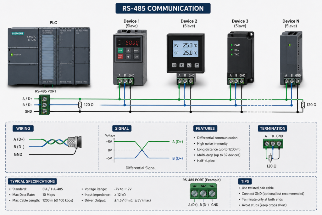
Random RS-485 communication failures often look like software problems.
The PLC reports a timeout. A Modbus RTU slave disappears for several seconds. PROFIBUS diagnostics show corrupted telegrams or a station repeatedly leaving the bus. Engineers begin changing baud rates, retry counts, protocol timeouts and device addresses.
Sometimes those settings are responsible.
In many live plants, however, the real fault is much closer to the cable tray.
RS-485 depends on two physical conditions:
- A clean differential signal between the two data conductors
- A common-mode voltage that remains inside the receiver’s electrical limits
When termination, grounding, shielding or cable routing is wrong, the protocol layer simply reports the consequences. Modbus may show CRC errors and timeouts. PROFIBUS may show bus faults, station dropouts or telegram retries.
Different fault messages can originate from the same damaged physical layer.
RS-485 Is a Physical Signal Before It Is a Protocol
Modbus RTU and PROFIBUS DP use different communication rules, telegram structures and timing requirements.
They nevertheless rely on differential signalling over an RS-485-style physical layer.
The receiver determines the logic state from the voltage difference between the two signal conductors:
Differential voltage = Voltage A − Voltage BBoth conductors may rise or fall relative to local earth while their difference remains valid. The problem begins when their absolute voltage relative to the receiver moves outside the transceiver’s common-mode range.
For conventional RS-485 interfaces, the commonly referenced operating envelope is approximately:
−7 V to +12 V common-mode voltageThe exact limit depends on the transceiver and device design.
When ground-potential differences or induced interference push the pair outside that envelope, the receiver may saturate and stop interpreting bits correctly.
The result can be:
- Missing frames
- CRC failures
- Framing errors
- Repeated retries
- Intermittent node dropouts
- Complete segment failure
The PLC generates the error message, but the PLC program may not be the cause.
Two Main Failure Families
Most difficult RS-485 faults can be placed into two broad groups.
Reflection and impedance faults
These distort the shape of individual bits.
Common causes include:
- Missing termination
- Extra termination
- Long cable stubs
- Star wiring
- Damaged cable geometry
- Crushed or sharply bent cable
- Incorrect cable impedance
- Loose connectors
Typical symptoms include:
- CRC errors
- Character corruption
- Failures that increase with baud rate
- One device failing more often than others
- Problems at the far end of a segment
- Communication improving when speed is reduced
Common-mode and EMC faults
These shift or contaminate the entire signal pair relative to the receiver.
Common causes include:
- Ground-potential differences
- Poor equipotential bonding
- Incorrect shield termination
- VFD interference
- Motor-cable coupling
- Unstable reference conductors
- Long runs between separate buildings or cabinets
- Surge or switching transients
Typical symptoms include:
- Several nodes dropping together
- Failure during motor starting
- Corruption during VFD acceleration
- Communication changes after grounding work
- Problems that depend on which machines are running
- Nodes recovering automatically after the transient ends
Recognizing the failure pattern can prevent hours of unnecessary protocol changes.
Common-Mode Voltage and the Missing Reference Problem
RS-485 is differential, but it is not infinitely isolated from ground.
The receiving transceiver still has a maximum allowable voltage between its local reference and the two communication conductors.
Two cabinets may each have a functional protective-earth connection while still sitting at different instantaneous electrical potentials. Those differences can be caused by:
- Long protective conductors
- High motor currents
- Poor bonding
- Separate building earth systems
- Lightning-induced surges
- VFD common-mode currents
- Heavy switching loads
If one end of the network rises several volts relative to the other, the full data pair can be shifted outside the receiving device’s operating range.
An RS-485 installation may therefore require a dedicated signal-reference conductor according to the device and network design.
The cable shield should not automatically be used as the communication reference or return conductor. Its main role is electromagnetic shielding.
Where large ground-potential differences are expected, galvanically isolated repeaters or isolated interfaces may be required.
Shielding Is Not a Universal One-End Rule
Shielding advice is frequently oversimplified.
A common rule says that a cable shield must always be grounded at one end only. That approach can reduce low-frequency circulating current in some instrumentation installations, but it is not universally correct for high-frequency industrial networks.
At higher frequencies, an unbonded or poorly bonded shield can behave like an antenna.
PROFIBUS installations, for example, commonly use low-impedance, large-area shield bonding at equipment entries, together with proper equipotential bonding. Generic Modbus RTU installations may follow different manufacturer recommendations depending on isolation, cable type and plant grounding.
The correct method depends on:
- Network specification
- Device manufacturer requirements
- Cable construction
- Frequency environment
- Equipotential-bonding system
- Isolation between nodes
- Whether the cable crosses buildings or grounding zones
Avoid treating the shield as an ordinary drain wire with a long pigtail where high-frequency EMC performance matters. A 360-degree shield connection generally provides a much lower high-frequency impedance than a long, thin conductor.
The installation should follow the requirements of the actual network and equipment—not a universal rule copied from an unrelated project.
What Happens When Shielding Is Wrong?
Incorrect shielding can fail in several ways.
Shield left floating
A completely unreferenced shield may absorb high-frequency electromagnetic energy from nearby drives, motors and switching equipment.
Possible results include:
- Random spikes
- Repeated CRC errors
- Communication failure at specific motor speeds
- Problems that disappear when nearby equipment stops
Shield carrying unintended current
When bonding and equipotential conditions are poor, current may flow through the shield.
That current can create magnetic fields and couple interference into the data pair.
Possible symptoms include:
- Errors during high plant load
- Communication changing after earth-bonding modifications
- Cable or connector heating in severe cases
- Several nodes failing together
Shield interrupted between cable sections
A shield that is connected at one end but broken at a junction box loses continuity.
The network may work at low speeds and fail at higher speeds or during VFD operation.
Long shield pigtails
A long pigtail may appear electrically connected when checked with a multimeter, yet perform poorly at high frequencies because of its inductance.
A DC continuity test alone does not prove good EMC performance.
Do Not Guess Ground-Loop Thresholds
Measuring voltage between grounding points can provide useful clues, but one arbitrary voltage threshold cannot diagnose every network.
A digital multimeter may show a low average voltage while fast high-frequency transients remain large enough to disturb communication. Conversely, a measurable DC difference does not automatically prove that it is causing the current fault.
Useful tests may include:
- AC and DC voltage between equipment references
- Shield current measurement
- Oscilloscope measurement during VFD operation
- Comparison between idle and loaded plant conditions
- Testing with an isolated repeater
- Inspection of the equipotential-bonding path
Measurements on live industrial systems must be performed by qualified personnel using appropriate instruments and safe procedures.
The objective is to correlate electrical disturbance with the communication failure—not merely to find any non-zero voltage.
VFDs and RS-485 Failures
Variable-frequency drives are among the most common sources of industrial network interference.
A VFD produces fast voltage transitions on its motor output. These transitions can create:
- Radiated electromagnetic fields
- Capacitive coupling
- Common-mode currents
- Ground-reference movement
- Conducted interference through power systems
A useful failure fingerprint is:
VFD starts or changes speed
↓
RS-485 error rate rises
↓
Nodes recover when the drive stops
When this pattern exists, inspect:
- Separation between communication and motor cables
- Motor-cable shield termination
- Drive and motor grounding
- Equipotential bonding
- Cable crossings and tray layout
- Network shield continuity
- Isolation between communication nodes
Changing Modbus register addresses will not correct interference from a poorly installed VFD motor cable.
Termination Controls Reflections
RS-485 cable behaves as a transmission line, especially as cable length and baud rate increase.
When a travelling signal reaches the end of the cable, it encounters the cable’s terminating impedance.
If the end is left open or terminated incorrectly, part of the signal energy is reflected back toward the transmitter.
The receiver may then see:
Original edge
+
Delayed reflected edge
=
Distorted bit waveform
The resulting waveform can contain:
- Overshoot
- Undershoot
- Ringing
- Multiple threshold crossings
- Smeared bit edges
At low speed on a short cable, the network may still work.
At higher speed or over a longer distance, the same reflection can corrupt frame boundaries and data bits.
Terminate Only the Physical Ends
A simple RS-485 bus is normally terminated at the two physical ends of the trunk.
It should not normally be terminated at every node.
For a network using 120-ohm cable and two 120-ohm terminators, the theoretical resistance measured across the pair with the network unpowered is:
120 Ω in parallel with 120 Ω = 60 ΩThis can be a useful diagnostic for many conventional Modbus RTU networks.
However, the measurement must be interpreted carefully.
The reading can be affected by:
- Bias resistors
- Connected transceivers
- Repeaters
- Isolation components
- Active termination
- Connector circuitry
- The resistance of the cable itself
PROFIBUS DP uses a specified cable and termination network that includes biasing. Its static resistance should not be judged using a generic “exactly 60 ohms” rule.
Always compare the measurement with the network’s actual electrical design.
Typical Resistance Findings on a Simple Passive RS-485 Bus
For a basic unpowered 120-ohm RS-485 trunk with uncomplicated passive termination:
| Approximate reading | Possible interpretation |
|---|---|
| Around 60 Ω | Two 120 Ω terminations likely present |
| Around 120 Ω | One termination may be missing |
| Very high resistance | Both terminations may be missing or circuit is open |
| Near 0 Ω | Short circuit or severe cable damage |
| Unexpected intermediate value | Extra termination, bias network or parallel path |
These values are diagnostic clues, not universal proof.
Before measuring resistance:
- De-energize the segment.
- Follow site electrical-safety procedures.
- Disconnect equipment where required by the test method.
- Confirm whether active termination requires power.
- Check the device and protocol documentation.
Never place an ohmmeter across an energized communication line.
Why One Missing Terminator Creates “Phantom” Timeouts
A missing terminator does not change the PLC’s protocol timeout directly.
It changes the electrical waveform.
A distorted bit causes the receiver to reject the frame. The master then waits for a valid response that never arrives. Only after the configured period expires does the PLC report a timeout.
The event chain is:
Reflection distorts a bit
↓
Frame fails validation
↓
Receiver discards the frame
↓
No valid response reaches the master
↓
Software timeout expires
The timeout is real from the processor’s perspective.
Its root cause is physical signal corruption.
Increasing the timeout may reduce how often the application reports an error, but it does not repair the damaged frame.
Stub Length and Topology
RS-485 generally works best as a linear trunk with short device connections.
Weak topologies include:
- Large star networks
- Long T branches
- Multiple unterminated spurs
- Rings without suitable repeaters
- Long drops to individual devices
Every branch introduces an impedance discontinuity.
At low baud rates, a short branch may be acceptable. At higher rates, the same branch can create significant reflection.
PROFIBUS DP is particularly sensitive to cable construction, connectors, termination and spur length at high speed.
A network operating at 12 Mbit/s has far less tolerance for careless cable geometry than a 9,600-baud Modbus segment.
Cable Damage Changes Electrical Behaviour
A cable does not need to be completely cut to fail.
Mechanical damage can change:
- Pair spacing
- Characteristic impedance
- Capacitance
- Shield continuity
- Conductor resistance
- Balance between the pair
Inspect for:
- Crushing under cable-tray covers
- Tight cable ties
- Sharp conduit bends
- Damaged connector entries
- Repeated flexing
- Heavy cabinet doors
- Water ingress
- Corroded junction boxes
- Poor field repairs
- Mixed cable types
A crushed PROFIBUS cable may still pass a continuity test while failing at high speed.
Continuity proves that copper exists. It does not prove signal integrity.
Modbus RTU Silent Timing
Modbus RTU uses silent intervals to separate frames.
At baud rates up to and including 19,200 baud, the commonly used character-time relationship is:
Character time = bits per character ÷ baud rateWith 11 bits per character:
Frame boundary = 3.5 × 11 ÷ baud rateAt 19,200 baud:
3.5 × 11 ÷ 19,200 ≈ 0.0020 secondsThat is approximately 2 milliseconds.
For baud rates above 19,200, the Modbus serial-line guidance commonly recommends fixed timing values of approximately:
- 750 microseconds for 1.5 character times
- 1.75 milliseconds for 3.5 character times
These timing rules are protocol requirements.
Signal reflections do not literally extend the configured silence period. Instead, waveform corruption can cause characters to be misread, rejected or interpreted with framing errors, leading to fragmented or discarded messages.
When diagnosing Modbus timeouts, inspect both:
- Protocol timing
- Physical waveform quality
Changing one cannot compensate reliably for a fault in the other.
PROFIBUS DP at High Speed
PROFIBUS DP can operate at much higher speeds than many Modbus RTU installations.
As speed increases, the network becomes more sensitive to:
- Cable type
- Segment length
- Connector quality
- Termination
- Spur length
- Shield bonding
- Cable damage
- Topology
At high speed, a small mechanical deformation can alter the cable’s electrical characteristics enough to reduce signal margin.
For PROFIBUS troubleshooting, verify:
- Approved PROFIBUS cable is used
- Connector termination switches are correct
- Both segment ends are terminated
- Terminated end devices remain powered where required
- No inappropriate stubs are present
- Shield bonding follows PROFIBUS installation practice
- Segment length matches baud rate
- Repeater placement is correct
Do not apply generic Modbus wiring assumptions to PROFIBUS without checking its specific installation rules.
Biasing and the Idle State
When no transceiver is actively driving the bus, the differential voltage can become undefined.
Bias resistors—sometimes called fail-safe biasing—establish a known idle state.
Potential problems include:
- No biasing on a network that requires it
- Biasing installed at several nodes
- Incorrect resistor values
- Biasing interacting with termination
- Devices with built-in biasing combined with external biasing
Incorrect biasing can cause:
- Random characters during idle periods
- False frame starts
- Communication failure when transmitters release the line
- Unstable startup behaviour
Determine where biasing is provided before adding more resistors.
Multiple bias networks can overload the drivers and change the expected resistance measurement.
A/B Labelling Is Not Consistent
One practical RS-485 problem is that manufacturers do not always label the differential conductors consistently.
Terms may include:
- A and B
- D+ and D−
- Rx+/Tx+ and Rx−/Tx−
- Non-inverting and inverting
- P and N
Some vendors use A for the inverting line, while others use A for the non-inverting line.
Do not connect devices based only on the letter.
Check the manufacturer’s electrical definition or terminal diagram.
A network with reversed conductors may fail completely or appear to work only through unusual device behaviour.
Separate True Timeouts From Corrupted Responses
A true application timeout may occur because:
- The slave is busy
- The slave task is overloaded
- The requested register does not exist
- The response timeout is genuinely too short
- The master polls too many devices
- Device processing is slow
- Serial parameters do not match
A physical-layer timeout may occur because:
- The request never reached the slave cleanly
- The response was corrupted
- A reflection damaged one character
- Common-mode voltage blinded the receiver
- Noise produced a CRC failure
- The node reset during a transient
Useful evidence includes:
- CRC error counters
- Framing-error counters
- Oscilloscope waveform
- Bus monitor capture
- Failure correlation with motor operation
- Node-specific dropout patterns
- Error rate at different baud rates
Reducing the baud rate can improve a marginal physical network, but it should be treated as a diagnostic clue rather than a substitute for repair.
A Structured RS-485 Troubleshooting Workflow
1. Freeze protocol changes
Record the current:
- Baud rate
- Parity
- Stop bits
- Device addresses
- Timeout
- Retry count
Do not change them until the physical layer has been inspected.
2. Identify the failure fingerprint
Determine whether the problem:
- Affects one node or the entire segment
- Appears during VFD operation
- Increases with cable length
- Changes with baud rate
- Began after grounding work
- Occurs at one machine position
- Appears only after cabinet doors move
3. Inspect the topology
Confirm:
- Linear trunk structure
- Termination at physical ends
- Short stubs
- Correct cable type
- No accidental star branches
- Correct repeater locations
4. Inspect the cable physically
Look for crushing, sharp bends, poor repairs, loose connectors and shield discontinuities.
5. Verify termination
With the segment safely de-energized, measure and interpret the line resistance according to the network’s real design.
6. Check shielding and bonding
Verify the installation follows the protocol and manufacturer requirements.
7. Check the signal reference
Confirm that the receiver common-mode range is not being exceeded and that the intended reference conductor or isolation is present.
8. Correlate errors with plant activity
Monitor communication while:
- VFDs start and stop
- Large motors start
- Contactors operate
- Welding equipment runs
- Production load changes
9. Capture the waveform
Where necessary, use an appropriate oscilloscope, differential probe or network analyser.
Observe:
- Differential amplitude
- Ringing
- Overshoot
- Common-mode movement
- Bit symmetry
- Noise bursts
10. Change protocol settings only after evidence
Once the physical layer is proven healthy, investigate software timing, polling load, frame spacing and device processing time.
Do Not Use the Shield as the Only Diagnostic
A shield continuity test is useful, but it is not enough.
Also verify:
- Pair continuity
- Pair resistance balance
- No conductor-to-shield short
- No conductor-to-earth leakage
- Correct polarity
- Correct termination
- Correct cable type
- Reference conductor integrity
- Device isolation
A shield can be continuous while the twisted pair is crushed or unbalanced.
When Isolation Is the Correct Repair
Some installations connect equipment across:
- Separate buildings
- Long outdoor runs
- Different grounding zones
- High-power electrical areas
- Large motors and drives
In these cases, better shielding alone may not solve the common-mode problem.
An isolated repeater or fibre-optic conversion can:
- Break unwanted galvanic paths
- Restore signal amplitude
- Divide a long network into segments
- Improve fault isolation
- Reduce common-mode exposure
Repeaters are not a replacement for correct topology and termination, but they can be essential where the physical installation exceeds the practical capability of one copper segment.
Final Thoughts
RS-485 failures frequently appear at the protocol layer while beginning in the cable, shield, termination or grounding system.
A Modbus timeout does not automatically mean that the timeout value is too short.
A PROFIBUS station dropout does not automatically mean that the device configuration is wrong.
The real cause may be:
- Reflections from an unterminated line
- A long cable stub
- Crushed communication cable
- VFD-induced interference
- Common-mode voltage outside the receiver range
- Incorrect shield bonding
- Missing signal reference
- Poor equipotential bonding
Before changing communication code, prove the physical layer.
Inspect the topology. Verify termination. Check shield integrity and grounding. Confirm data freshness and capture the actual waveform when necessary.
You cannot reliably program around an impedance mismatch, damaged cable or common-mode electrical fault.
Make the copper path honest first.
Then investigate the protocol.