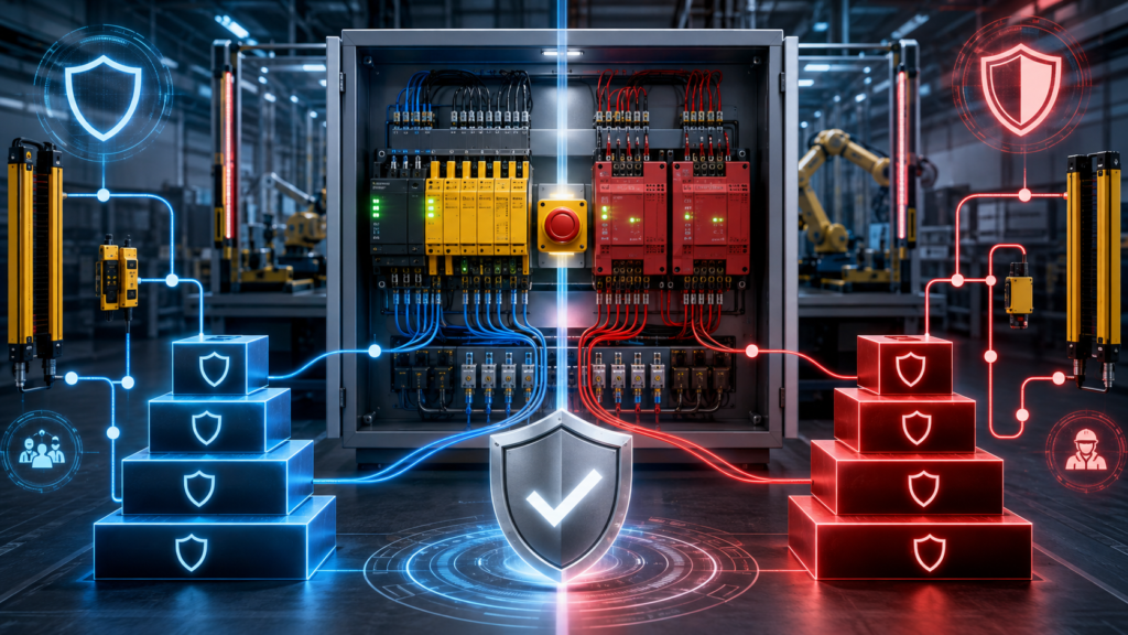
Machine-safety terminology can become confusing very quickly.
A specification might require:
Category 3, PL dAnother drawing may state:
SIL 2A safety relay is marked:
PLe / SIL 3Then somebody asks whether a dual-channel emergency stop is “Category 4.”
These terms are related, but they do not mean the same thing.
- Category describes the architecture and fault behaviour of a safety-related control system.
- PL, or Performance Level, describes the reliability achieved under ISO 13849-1.
- SIL, or Safety Integrity Level, describes the integrity achieved under IEC 62061.
- PLr and the required SIL come from the risk assessment for a particular safety function.
A Category 3 circuit does not automatically achieve PL d. A safety relay marked PLe does not make the entire machine PLe. SIL 2 is not another name for Category 3.
The complete safety function must be designed, calculated, verified and validated.
Safety warning: This article is an introduction, not a machine-safety design procedure. Safety functions should be designed and validated by competent people using the applicable machinery standards, manufacturer data and machine-specific risk assessment.
Quick Comparison
| Term | Standard | What it describes | Levels |
|---|---|---|---|
| Category | ISO 13849-1 | Architecture and behaviour when faults occur | B, 1, 2, 3 and 4 |
| PLr | ISO 13849-1 | Performance Level required by the risk assessment | a to e |
| PL | ISO 13849-1 | Performance Level actually achieved | a to e |
| SIL required | IEC 62061 | Safety integrity required by the risk assessment | SIL 1 to SIL 3 |
| SIL achieved | IEC 62061 | Safety integrity achieved by the complete safety function | SIL 1 to SIL 3 |
| PFH<sub>D</sub> | Both | Average frequency of dangerous failure per hour | Numerical value in 1/h |
The current ISO control-system design standard is ISO 13849-1:2023. It covers safety-related control systems using electrical, hydraulic, pneumatic and mechanical technologies in high-demand and continuous operating modes.
The current IEC machinery functional-safety standard is IEC 62061:2021, updated by Amendment 1 in 2024 and Amendment 2 in March 2026. The 2021 edition covers the design, integration and validation of machine safety-related control systems and expanded its scope to include non-electrical technologies.
Begin With the Safety Function
Category, PL and SIL are assigned to safety functions, not vaguely to the whole machine.
Examples of safety functions include:
- Opening a guard door stops hazardous motion.
- Pressing an emergency-stop button removes torque.
- Breaking a light curtain prevents a press stroke.
- Excessive speed causes a controlled safe stop.
- A two-hand control prevents a cycle unless both buttons are operated correctly.
- A locked guard remains locked until dangerous motion has stopped.
A safety function normally includes three sections:
Input
→ Logic
→ Output
For a guard-door safety function, that might be:
Guard switches
→ Safety relay or safety PLC
→ Contactors, drive STO or safety valves
Every section matters.
A PLe safety relay connected to an unsuitable single contactor and a poorly selected switch does not produce a PLe safety function. The achieved level must cover the sensor, logic, output devices, wiring, diagnostics, fault behaviour and systematic measures.
Required Level Versus Achieved Level
This distinction is essential.
PLr or required SIL
The risk assessment determines how much risk reduction the safety function must provide.
Under ISO 13849-1, this is expressed as:
PLr a, b, c, d or eUnder IEC 62061, it is expressed as:
SIL 1, SIL 2 or SIL 3A machine-specific Type-C standard may already specify the required level for a particular safety function. When it does not, the designer must determine the requirement through the risk-assessment process.
PL or SIL achieved
After designing the safety system, the designer determines what the actual circuit achieves.
The result must meet or exceed the requirement:
PL achieved ≥ PLror:
SIL achieved ≥ SIL requiredReaching a higher numerical level is not an excuse to ignore the architecture, application conditions, software process or validation requirements.
How PLr Is Determined
ISO 13849-1 uses risk estimation to determine the required Performance Level for each safety function.
A commonly used risk graph considers:
Severity: S
- S1: Slight, normally reversible injury
- S2: Serious, normally irreversible injury or death
Frequency or exposure: F
- F1: Seldom or less frequent exposure, or short exposure time
- F2: Frequent or continuous exposure, or long exposure time
Possibility of avoidance: P
- P1: Avoidance or limitation of harm may be possible under certain conditions
- P2: Avoidance is scarcely possible
Following the route through the graph produces a required level from PLr a to PLr e. Machine-specific standards and a detailed risk assessment take priority over casually selecting values from a simplified online diagram.
For example, a hazard involving possible death, frequent access and almost no realistic chance of escape will generally require a much higher level than a slow mechanism producing a minor reversible injury with rare exposure.
The answer is not automatically PL e simply because an emergency-stop button is involved.
What Is a Safety Category?
ISO 13849-1 defines five architecture categories:
B, 1, 2, 3 and 4The category describes how the safety-related control system is structured and how it behaves when faults occur.
It is only one part of the PL evaluation.
Category B
Category B is the basic architecture.
It normally uses a single functional channel and appropriate components designed and installed according to basic safety principles.
A fault can cause the safety function to be lost.
Conceptually:
Input
→ Logic
→ Output
There is no required redundancy or automatic diagnostic coverage.
Category B is associated with lower levels of risk reduction. It is not normally suitable where one undetected fault could expose someone to severe harm.
Category 1
Category 1 is also generally single-channel, but it uses:
- Well-tried components
- Well-tried safety principles
- Components with greater reliability
The probability of failure is lower than in Category B, but one fault can still result in loss of the safety function.
A mechanically linked safety switch controlling a suitably selected contactor through well-tried principles might form part of a Category 1 architecture, depending on the complete design.
Category 1 relies heavily on component reliability. It does not obtain fault tolerance merely by using better-quality parts.
Category 2
Category 2 introduces periodic testing.
A simplified architecture looks like this:
Functional channel
        +
Test and monitoring function
The safety function is checked at suitable intervals. When the test detects a fault, the system initiates an appropriate reaction or prevents continued operation.
The important limitation is that a dangerous fault may exist between test intervals. The safety function could therefore be lost before the next test detects the problem.
The test rate, demand rate, fault reaction and effectiveness of the monitoring are critical. Category 2 is not simply Category 1 with an auxiliary feedback contact.
Category 3
Category 3 normally uses a redundant or dual-channel architecture.
Conceptually:
Input channel 1 → Logic channel 1 → Output channel 1
        ╲              monitoring             ╱
Input channel 2 → Logic channel 2 → Output channel 2
A single fault must not cause loss of the safety function.
Some faults are detected, but not every possible fault must be detected immediately. An accumulation of undetected faults can eventually cause the safety function to be lost.
A common Category 3 arrangement may include:
- Dual-channel emergency-stop contacts
- A safety relay or safety PLC
- Two output contactors
- Feedback monitoring of the contactors
Whether that architecture achieves PL c or PL d depends on component reliability, diagnostic coverage, common-cause protection and the rest of the ISO 13849 calculation.
Category 4
Category 4 also uses redundancy, but with higher reliability and more extensive diagnostics.
A single fault must not cause loss of the safety function. Faults are detected at or before the next demand where reasonably practicable, and an accumulation of faults must not lead to the loss of the safety function.
Category 4 normally requires:
- Dual-channel architecture
- High MTTF<sub>d</sub>
- High diagnostic coverage
- Strong protection against common-cause failures
- Appropriate fault reaction
- Detailed verification and validation
Category 4 is commonly associated with PL e, but writing “two channels” on a schematic does not make the system Category 4.
Rockwell’s summary of the ISO architectures describes Categories B and 1 as single-channel structures, Category 2 as a tested architecture, and Categories 3 and 4 as dual-channel structures with progressively stronger diagnostic and reliability requirements.
Category Is Not the Same as PL
This is the most common misunderstanding.
The achieved Performance Level depends on several elements:
Category
+
MTTFd
+
DCavg
+
CCF measures
+
Systematic-failure measures
+
Software and validation requirements
A circuit cannot be declared PL d merely because it looks like Category 3.
The simplified ISO relationship can be represented approximately as follows:
| Category | Typical architecture | Diagnostics | Typical possible PL range* |
|---|---|---|---|
| B | Single channel | None required | PL a to PL b |
| 1 | Reliable single channel | None required | Up to PL c |
| 2 | Tested architecture | Low to medium | PL a to PL d |
| 3 | Redundant channels | Low to medium | PL b to PL d |
| 4 | Redundant, fault-tolerant | High | Up to PL e |
*The actual result depends on all applicable ISO 13849 requirements and calculations. This is not a design-selection table.
Schneider Electric’s published ISO 13849 evaluation guidance shows that the PL result changes according to the combination of category, MTTF<sub>d</sub> and diagnostic coverage.
What Is MTTF<sub>d</sub>?
MTTF<sub>d</sub> means:
Mean Time to Dangerous FailureIt is a statistical reliability measure used for individual channels or components.
ISO 13849 groups MTTF<sub>d</sub> values into broad classes such as:
- Low
- Medium
- High
It does not mean that a component will definitely run for that number of years before failing. It is a probabilistic value used in the safety calculation.
For electromechanical devices such as contactors and switches, the calculation often also depends on:
- B10d data
- Number of operations per year
- Operating frequency
- Duty cycle
- Mission time
A contactor that switches twice a day and one that switches every five seconds cannot be treated as having the same operational lifetime.
What Is Diagnostic Coverage?
DC, or Diagnostic Coverage, describes how effectively the system detects dangerous failures.
Examples include:
- Monitoring both channels of an emergency-stop circuit
- Detecting short circuits between input channels
- Checking for welded contactor contacts
- Monitoring safety-output feedback
- Comparing redundant sensor signals
- Detecting discrepancies between two channels
- Safety PLC self-diagnostics
ISO 13849 commonly evaluates the average diagnostic coverage as DC<sub>avg</sub>.
Greater diagnostic coverage can support a higher PL, but only when the diagnostics genuinely detect relevant dangerous faults.
A PLC alarm saying “contactor failed” after the motor has already restarted uncontrollably is not particularly useful diagnostic coverage.
What Is CCF?
CCF means:
Common Cause FailureRedundancy only helps when both channels do not fail for the same reason.
Common-cause failures can include:
- Two wires damaged by the same mechanical impact
- Both channels shorted together in one cable
- Water entering both sensors
- Excessive temperature affecting both devices
- Electromagnetic interference affecting both channels
- Shared loss of power
- Incorrect software or configuration applied to both channels
- Two identical valves contaminated by the same material
ISO 13849 therefore requires measures addressing separation, environmental conditions, diversity, sound design and other common-cause factors.
Two contactors sitting beside one another are redundant components. They are not automatically protected against every common cause.
Performance Levels and PFH<sub>D</sub>
PL ranges from a to e.
- PL a provides the lowest risk reduction.
- PL e provides the highest.
Each level corresponds to a range of average dangerous failures per hour:
| Performance Level | PFH<sub>D</sub> range per hour |
|---|---|
| PL a | ≥ 10⁻⁵ and < 10⁻⁴ |
| PL b | ≥ 3 × 10⁻⁶ and < 10⁻⁵ |
| PL c | ≥ 10⁻⁶ and < 3 × 10⁻⁶ |
| PL d | ≥ 10⁻⁷ and < 10⁻⁶ |
| PL e | ≥ 10⁻⁸ and < 10⁻⁷ |
PFH<sub>D</sub> is a probability-based measure. A lower value represents a lower average frequency of dangerous failure and therefore greater integrity.
Do not interpret the figures as a promise that an accident can occur only once every several million hours. The calculation concerns dangerous failure of the safety function and depends on assumptions, component data, mission time, use conditions and systematic controls.
What Is SIL?
SIL means:
Safety Integrity LevelIEC 62061 uses SIL for machinery safety-related control functions.
For machinery applications covered by IEC 62061, the available levels are:
- SIL 1
- SIL 2
- SIL 3
SIL 3 provides the greatest risk reduction of the three.
IEC 62061 is a machinery-sector standard within the broader IEC 61508 functional-safety framework. The current edition addresses the safety lifecycle, requirements specification, system design, subsystem architecture, hardware reliability, software, verification and validation.
SIL and PFH<sub>D</sub>
For high-demand or continuous-mode machinery safety functions:
| Safety Integrity Level | PFH<sub>D</sub> range per hour |
|---|---|
| SIL 1 | ≥ 10⁻⁶ and < 10⁻⁵ |
| SIL 2 | ≥ 10⁻⁷ and < 10⁻⁶ |
| SIL 3 | ≥ 10⁻⁸ and < 10⁻⁷ |
The higher the SIL, the lower the permitted dangerous-failure frequency and the greater the required integrity of the safety function. IEC guidance describes SIL as a property of a safety function rather than a general label for an entire factory or machine.
How PL and SIL Compare
PL and SIL use overlapping PFH<sub>D</sub> ranges.
A simplified numerical comparison is:
| ISO 13849 Performance Level | Approximate IEC 62061 relationship |
|---|---|
| PL a | No direct SIL equivalent |
| PL b | Within the SIL 1 PFH<sub>D</sub> range |
| PL c | Within the SIL 1 PFH<sub>D</sub> range |
| PL d | Within the SIL 2 PFH<sub>D</sub> range |
| PL e | Within the SIL 3 PFH<sub>D</sub> range |
This does not mean you can replace “PL d” with “SIL 2” everywhere in the technical file.
The numerical failure ranges overlap, but ISO 13849 and IEC 62061 use different design, architectural, systematic, software and verification methods.
A safety function should be evaluated under the standard selected for the design rather than calculated partly under one and declared under the other because the final numbers happen to look similar.
ISO 13849 vs IEC 62061
ISO 13849-1
ISO 13849-1 is commonly used for machinery containing combinations of:
- Electromechanical safety relays
- Safety PLCs
- Contactors
- Hydraulic valves
- Pneumatic valves
- Mechanical interlocks
- Safety switches
- Light curtains
- Drives with integrated safety functions
It uses the familiar categories B, 1, 2, 3 and 4, together with reliability, diagnostics and common-cause considerations.
Its final result is a Performance Level.
The current 2023 edition applies across electrical, hydraulic, pneumatic and mechanical technologies and includes requirements for safety-related software.
IEC 62061
IEC 62061 uses a functional-safety lifecycle and subsystem approach.
The designer defines the safety function, assigns its required SIL, divides the function into subsystems and verifies the complete safety-related control system.
The 2021 edition introduced a functional-safety plan, expanded requirements for parameterisation, periodic testing, software verification and validation, and changed older terminology from SIL claim limit, or SILCL, toward the maximum SIL of a subsystem. Older manuals and component certificates may still use SILCL terminology.
Its final result is a Safety Integrity Level.
Which Standard Should You Use?
Neither standard is universally “better.”
Use the machine-specific Type-C standard when it specifies a method or required level.
Otherwise, consider:
ISO 13849 may be more convenient when:
- The organisation already uses SISTEMA.
- Category-based architectures are familiar.
- The design combines electrical, pneumatic, hydraulic and mechanical components.
- Manufacturer SISTEMA libraries are readily available.
- The safety functions are relatively conventional.
IEC 62061 may be attractive when:
- The organisation uses a formal functional-safety lifecycle.
- The system contains complex programmable control.
- Requirements and subsystem design are already organised around SIL.
- The customer or project specification explicitly requests IEC 62061.
- The company has established IEC 61508-style processes.
The selected method should be followed consistently throughout design, verification and validation.
SISTEMA and ISO 13849 Calculations
SISTEMA is a free software tool provided by the German Institute for Occupational Safety and Health, IFA.
It helps designers model safety functions and evaluate ISO 13849 parameters such as:
- Categories
- MTTF<sub>d</sub>
- DC<sub>avg</sub>
- CCF
- PFH<sub>D</sub>
- Achieved PL
IFA assigns SISTEMA versions to specific revisions of ISO 13849-1. Version compatibility matters because the 2023 standard introduced changes that required updates to the software.
SISTEMA performs calculations. It does not:
- Conduct the risk assessment for you
- Design the circuit
- Confirm that wiring matches the model
- Validate stopping time
- Test the physical machine
- Prove that the chosen safety function is appropriate
- Replace competent engineering judgement
A green result in a software report is useful. It is not magical certification dust.
Practical Example: Guard-Door Monitoring
Suppose a machine has a guarded hazardous area.
The safety function is:
Opening the guard must stop hazardous motion and prevent restart until the guard is closed and a valid reset has occurred.
The risk assessment determines:
PLr dA possible architecture might include:
Two-channel guard switch
→ Safety relay
→ Two contactors
→ External device monitoring
The calculation would need data for:
- The guard-switch subsystem
- Safety relay
- Output contacts
- Contactors
- Operating frequency
- Diagnostic coverage
- Common-cause measures
- Mission time
The physical validation would also need to confirm:
- Opening the guard causes the required stop
- A single-channel fault does not defeat the function
- Welded contactors prevent restart
- Cross faults are handled as intended
- Reset does not initiate hazardous movement
- The guard is far enough away, or locked until the hazard stops
- Stopping time remains within the validated limit
- Bypasses and foreseeable misuse have been considered
The fact that the relay data sheet says PLe is only one input to that process.
Category 3 PL d Versus SIL 2
These are often treated as equivalents because their quantitative performance can occupy the same PFH<sub>D</sub> range.
A Category 3, PL d safety function typically has:
- Redundant channels
- Tolerance of a single fault
- Some fault detection
- Suitable component reliability
- Common-cause protection
- PFH<sub>D</sub> within the PL d band
A SIL 2 function under IEC 62061 must meet:
- SIL 2 PFH<sub>D</sub>
- Relevant subsystem architectural constraints
- Systematic capability requirements
- Software requirements where applicable
- Safety-lifecycle, verification and validation requirements
The achieved risk reduction may be comparable, but the path used to demonstrate it is not identical.
Write the level actually designed and assessed:
Category 3, PL d according to ISO 13849-1or:
SIL 2 according to IEC 62061Do not casually combine them into an unofficial new standard.
Safety Category Is Not Stop Category
This mistake appears frequently in maintenance discussions.
Safety categories
These come from ISO 13849:
Category B, 1, 2, 3 and 4They describe safety-system architecture and fault behaviour.
Stop categories
These come from machine electrical-safety requirements:
Stop Category 0
Stop Category 1
Stop Category 2
They describe how motion is stopped.
In simplified terms:
- Stop Category 0: Immediate removal of power to the actuators
- Stop Category 1: Controlled stop followed by removal of power
- Stop Category 2: Controlled stop with power remaining available
A safety function could be:
Stop Category 1
implemented by a Category 3, PL d control system
There is no contradiction. The two “categories” describe different things.
Common Mistakes
“It has two channels, so it is Category 4”
Two channels create redundancy. Category 4 also requires high reliability, strong diagnostics, suitable fault reaction and resistance to accumulated faults.
“The relay is SIL 3, so the machine is SIL 3”
The relay is only the logic subsystem. The sensors, wiring and final switching elements must also be evaluated.
“Every emergency stop must be PLe”
The required level comes from the machine risk assessment or applicable machine-specific standard.
“Category 3 always means PL d”
Category is only part of the calculation. A weak Category 3 design may achieve a lower PL.
“A normal PLC can monitor the safety relay, so the PLC is part of the safety function”
Standard PLC monitoring can provide useful diagnostics. It should not be assumed to perform the safety function unless it has been appropriately designed and evaluated for that purpose.
“Feedback from one auxiliary contact proves the motor stopped”
Contactor feedback may indicate contactor state. It does not necessarily prove that hazardous motion has ended.
“The safety circuit worked during commissioning, so it is validated”
Validation includes analysis and testing against the safety requirements, including expected faults and foreseeable operating conditions.
Verification and Validation
Verification asks:
Was the safety-related control system designed correctly according to its requirements?
Validation asks:
Does the completed safety function actually provide the required behaviour and risk reduction on the real machine?
ISO 13849-2:2012 remains the published validation standard as of August 2026. It specifies validation by analysis and testing of safety functions, categories and achieved Performance Levels. ISO is developing a replacement, but the revision remains at draft stage.
Validation should consider more than pressing the emergency stop once.
Depending on the function, testing may include:
- Opening each input channel separately
- Creating a short between channels where relevant
- Simulating welded output contacts
- Interrupting feedback monitoring
- Disconnecting a sensor
- Removing power and restoring it
- Checking restart behaviour
- Measuring stopping time
- Testing manual and automatic modes
- Confirming fault indications
- Reviewing safety software
- Confirming that actual wiring matches the drawings
- Recording test results and acceptance criteria
The validation plan should be prepared from the safety requirements—not invented after the machine has already shipped.
A Practical Workflow
A sensible process looks like this:
1. Perform the machine risk assessment.
2. Identify every required safety function.
3. Describe the safe state and required response.
4. Determine PLr or required SIL.
5. Select ISO 13849-1 or IEC 62061.
6. Design the input, logic and output subsystems.
7. Collect manufacturer reliability data.
8. Calculate the achieved PL or SIL.
9. Verify architecture, diagnostics and systematic measures.
10. Install and commission the system.
11. Validate the complete safety function.
12. Document assumptions, calculations and test results.
13. Control future modifications.
Skipping directly from step 2 to buying a safety relay is how expensive redesigns begin.
Final Thoughts
The simplest way to remember the terminology is:
Category
= How the architecture behaves under faults
PL
= Performance achieved under ISO 13849-1SIL
= Safety integrity achieved under IEC 62061PLr or required SIL
= What the risk assessment says the function needsCategory, PL and SIL are not labels earned by purchasing a particular relay or PLC.
They describe the performance of a complete safety function:
Sensor
→ Logic
→ Final switching element
→ Safe machine response
The design must work normally, survive the faults required by its architecture and be proven through calculation and physical validation.
Functional safety is not about making a machine impossible to operate.
It is about ensuring that when the safety system is needed, it does the one job everybody is relying on it to do.