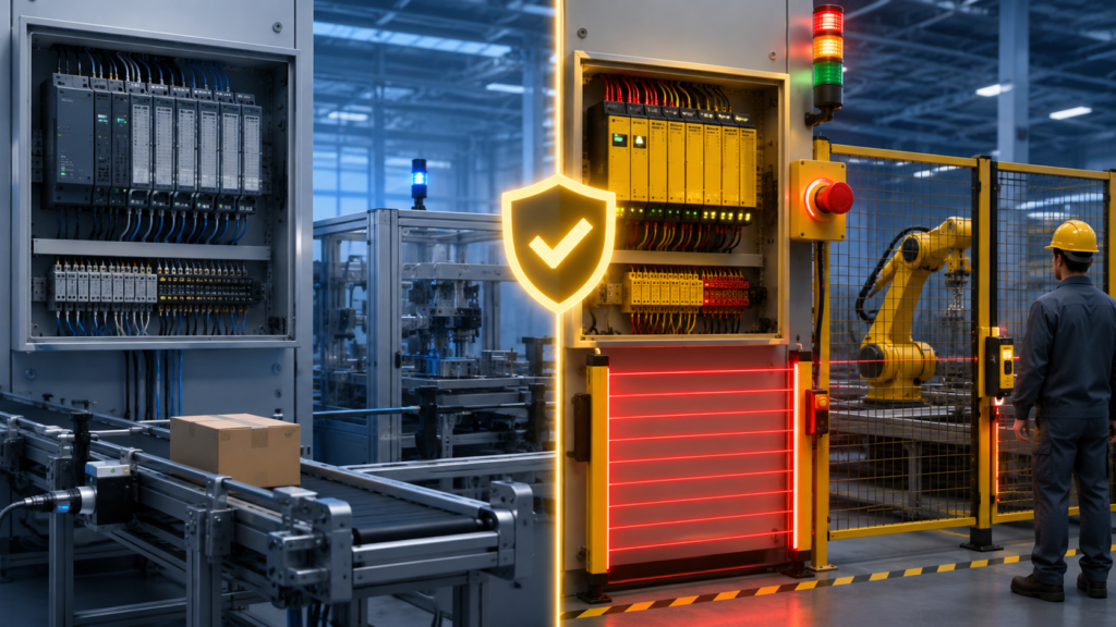
A standard PLC can stop a motor.
That does not automatically make it suitable for machine safety.
You could write a rung that turns off a contactor when an emergency-stop button is pressed. Under normal conditions, it may appear to work perfectly. The problem appears when an input fails, an output sticks, a program change introduces an error or communication is lost.
A safety function must continue to provide the required protection even when specified faults occur. That requires more than ordinary PLC logic.
A safety PLC is designed and certified for safety-related control functions. A standard PLC controls normal machine operation but should not be assumed to provide personnel protection unless the complete control system has been designed and validated for that safety purpose.
That does not mean every machine needs a safety PLC.
Many small machines can be protected perfectly well using a certified safety relay. Safety PLCs become valuable when the number, complexity and interaction of safety functions make a relay-based system difficult to build, diagnose or expand.
Safety warning: The need for a safety PLC must be determined through a machine risk assessment and the applicable machinery standards. This article is an introduction, not a substitute for safety-system design, verification or validation by competent personnel.
Quick Comparison
| Feature | Standard PLC | Safety PLC |
|---|---|---|
| Main purpose | Normal machine and process control | Safety-related and standard control |
| Typical functions | Sequences, timers, production logic, HMI and communications | Emergency stops, guard monitoring, safe zones and safe motion control |
| Certified for safety functions | Normally no | Yes, within stated limits and conditions |
| Internal diagnostics | General controller diagnostics | Safety-specific hardware and software diagnostics |
| Safety program separation | Not applicable | Safety logic separated and protected from standard logic |
| Safety I/O support | Standard I/O | Fail-safe or safety-rated I/O |
| Safety communication | Ordinary industrial communication | Certified safety communication where supported |
| Change management | Normal project controls | Safety locking, signatures, validation and documented change procedures |
| Suitable for sole emergency-stop function | Normally no | Potentially, as part of a validated complete safety function |
| Typical alternative | Standard PLC plus safety relay | Not always needed on simple machines |
What Is a Standard PLC?
A standard PLC is designed to control the normal operation of machinery.
Typical responsibilities include:
- Starting and stopping motors during production
- Operating valves and cylinders
- Controlling machine sequences
- Reading sensors
- Managing recipes
- Communicating with drives and HMIs
- Generating production alarms
- Collecting data
- Coordinating automatic and manual modes
It is expected to operate reliably, but ordinary PLC reliability is not the same as functional safety.
Imagine that a standard PLC controls a conveyor. Its normal program may contain:
Run request
AND
Automatic mode
AND
No overload
AND
Downstream conveyor ready
→ Conveyor output
That is normal control logic.
Now imagine using another ordinary rung for an emergency stop:
Emergency stop healthy
→ Allow conveyor output
The conveyor may stop every time the emergency-stop button is tested. Nevertheless, the design may not detect:
- A short circuit bypassing the emergency-stop contact
- A failed PLC input
- A stuck output transistor
- A welded contactor
- An unintended program modification
- Corrupted or incorrect logic
- A network failure that leaves an output active
- A fault shared by multiple control channels
The fact that the program works during normal testing does not prove that it provides the required behaviour under fault conditions.
What Is a Safety PLC?
A safety PLC—also called a fail-safe PLC or safety controller—is designed for safety-related control functions.
It combines certified hardware, firmware, programming restrictions, diagnostics and safety-oriented software measures to achieve a defined level of functional safety when used within the manufacturer’s stated conditions.
The complete safety function may be evaluated under standards such as:
- ISO 13849-1, using Categories and Performance Levels
- IEC 62061, using Safety Integrity Levels
ISO 13849-1:2023 provides requirements and methods for designing safety-related parts of machine control systems, including their software. IEC 62061:2021, together with its 2024 and 2026 amendments, covers the design, integration and validation of machine safety-related control systems.
IEC 62061 is a machinery-sector standard developed within the broader IEC 61508 functional-safety framework for electrical, electronic and programmable electronic safety-related systems.
A safety PLC may perform functions such as:
- Emergency-stop monitoring
- Safety-door monitoring
- Light-curtain processing
- Two-hand control
- Safe zone control
- Restart prevention
- Contactor feedback monitoring
- Safe speed monitoring
- Safe direction monitoring
- Safe limited speed
- Safe torque off control
- Muting and blanking logic
- Safety communication between machine sections
The controller is still only one part of the safety function.
A typical architecture is:
Safety sensor
→ Safety input
→ Safety PLC logic
→ Safety output
→ Contactors, valves or drive safety function
→ Hazard reaches safe state
Every part must be considered in the safety calculation and validation.
What Makes a Safety PLC Different?
The difference is not simply a sticker marked “SIL 3.”
A safety PLC uses a controlled system architecture intended to detect dangerous internal and external faults and bring the affected safety function to a safe state when required.
Exact implementations differ between manufacturers, but safety platforms commonly include:
- Internal hardware diagnostics
- Program-execution monitoring
- Safety-specific data protection
- Restricted or certified safety instructions
- Fail-safe input and output processing
- Detection of communication faults
- Safety-program signatures
- Password or access protection
- Controlled transfer of standard data into safety logic
- Defined fault responses
- Safety-task watchdogs
- Safety network identities and connection monitoring
For example, Rockwell states that the GuardLogix safety task is the task certified for safety applications. Safety tags can be read by standard logic, but safety data can only be written by authorised safety logic or another supported safety controller.
Siemens describes its fail-safe PLC system as using a dedicated safety program and fail-safe I/O. Additional checks and fault-response functions are inserted so faults can be detected and the system brought to or maintained in a safe state.
These features help prevent an ordinary program error or standard task from silently defeating the safety function.
They do not remove the need for competent design.
A Safety PLC Can Also Run Standard Logic
Many modern safety controllers can run both:
Standard machine logic
+
Safety-related logic
That does not mean the two programs are freely mixed together.
They are deliberately separated.
A GuardLogix controller, for example, contains standard tasks and a dedicated safety task. Standard routines cannot be executed from inside the safety task, and changes to safety-related elements affect the safety signature and require revalidation.
A Siemens F-PLC can similarly execute standard and safety programs while protecting safety-related data against unintended influence from the standard program.
This integrated architecture can reduce hardware and allow normal automation and safety diagnostics to share one engineering environment.
It does not turn ordinary ladder logic into safety logic. Safety functions must still be programmed inside the certified safety environment using the approved instructions and design rules.
Does Every Emergency Stop Require a Safety PLC?
No.
An emergency-stop function requires an appropriately designed safety-related control system. That system may use:
- A safety relay
- A configurable safety relay
- A safety PLC
- A safety controller integrated into another control platform
- A combination of certified safety devices
A small machine with one emergency-stop button, one guard switch and two contactors may not benefit from a programmable safety controller.
A certified safety relay can monitor the input channels, control the output devices and monitor their feedback. Rockwell specifically recommends certified safety relays for applications such as emergency stops and safety interlocking.
The required solution depends on:
- The risk assessment
- Number of safety functions
- Required PL or SIL
- Number of machine zones
- Diagnostic requirements
- Required stopping behaviour
- Expansion plans
- Machine-specific standards
- Complexity of the safety logic
The question is not:
Does this machine have an emergency stop?
The useful question is:
What safety functions are required, and what architecture is the most appropriate way to achieve and validate them?
When a Safety Relay Is Usually Enough
A safety relay is often the simpler choice when the machine has only a few straightforward safety functions.
For example:
One emergency-stop circuit
One guard switch
One safety zone
Two contactors
Manual reset
Contactor feedback monitoring
A safety relay may be preferable because it offers:
- Simple wiring
- A clear and limited function
- Lower software complexity
- Easy fault tracing
- Lower hardware cost
- No programmable safety application to manage
- Straightforward replacement when documented properly
Safety relays are available for more than emergency stops. Depending on the device, they can monitor guards, light curtains, two-hand controls, speed, standstill and other functions.
The drawback appears when several relays must interact.
A panel containing twelve safety relays, multiple expansion modules, dozens of cross-connections and several timing functions may be harder to understand than one properly designed safety PLC system.
At that point, avoiding a safety PLC does not necessarily make the system simpler.
When You Actually Need a Safety PLC
“Need” does not always mean that no other solution is technically possible.
It usually means a safety PLC is the most practical, scalable and verifiable architecture for the required safety functions.
1. The Safety Logic Is Complex
A safety relay is excellent at performing one clearly defined function.
A safety PLC becomes useful when safety decisions depend on combinations of:
- Machine operating mode
- Guard-door position
- Robot location
- Product position
- Zone occupancy
- Drive status
- Safe speed
- Enabling devices
- Maintenance mode
- Reset conditions
- Multiple safety devices
Consider a packaging line with five guarded sections.
Opening Guard 1 may need to stop only Zone 1. Opening Guard 3 may stop Zones 2, 3 and 4. An emergency stop may stop the complete line. Maintenance mode may allow one conveyor to operate at limited speed with a hold-to-run enabling device.
That logic can technically be built using relays.
It may require an impressive amount of wiring and an equally impressive amount of patience from the person who later has to diagnose it.
A safety PLC allows the safety functions and zone relationships to be defined in a structured, documented application—provided the design process and validation remain rigorous.
2. The Machine Has Multiple Safety Zones
A safety PLC is especially useful when a machine is divided into independent safety zones.
Examples include:
- Long conveyor lines
- Packaging systems
- Palletising systems
- Automated warehouses
- Assembly lines
- Multi-station production equipment
- Robot cells with several access points
Stopping the entire machine whenever one guard opens may be safe, but it can create unnecessary production loss.
A correctly designed zoned system can stop only the hazardous equipment affected by the opened guard while allowing other safe sections to continue operating.
This requires carefully controlled logic.
The designer must consider:
- Shared hazards between zones
- Movement crossing zone boundaries
- Material transferred between sections
- Restart behaviour
- Emergency-stop coverage
- Stored energy
- Communication failures
- Which devices must stop together
A safety PLC does not make zone control automatically correct. It provides a practical platform on which the required safety logic can be implemented and diagnosed.
3. You Need Distributed Safety I/O
Large machines may have safety devices spread across considerable distances.
Hardwiring every emergency stop, guard switch and light curtain back to one central panel can require large quantities of cable.
A safety PLC system can use certified safety communication with distributed safety I/O, allowing safety data to be transported over an industrial network while maintaining the required safety measures.
This is common on:
- Large conveyor systems
- Automotive production lines
- Distributed process machines
- Warehouses
- Airport material-handling systems
- Long packaging and manufacturing lines
The network itself does not become physically perfect. Safety communication protocols add measures that detect problems such as incorrect addressing, delays, repeated messages, corrupted data and lost connections according to the certified system design.
The exact controller, network, I/O and device combination must be used within its safety certification and instructions.
4. You Need Advanced Drive Safety Functions
A simple motor may only require torque to be removed.
A more complex application may need:
- Safe Torque Off
- Safe Stop 1
- Safe Stop 2
- Safe Limited Speed
- Safe Direction
- Safe Operating Stop
- Safe Position
- Safely Limited Position
- Safe Brake Control
These functions are common in servo systems, robots, printing equipment, winders, machine tools and production machinery requiring controlled access.
For example, maintenance personnel may need to enter an area while an axis moves slowly under an enabling device.
Simply disconnecting motor power would make the required maintenance operation impossible. The safety system must instead monitor speed and operating mode while ensuring that the axis cannot exceed the validated safe limit.
That generally requires integrated safety-capable drives, sensors where required and safety logic capable of coordinating the function.
5. You Need Light-Curtain Muting
Muting temporarily suspends a protective device under tightly controlled conditions.
A typical example is a pallet leaving a guarded conveyor through a light curtain. The pallet must pass through, while a person must not be able to follow it into the hazard area.
The system may evaluate:
- Several muting sensors
- Sensor activation order
- Sensor timing
- Conveyor direction
- Material presence
- Muting timeout
- Partial blockage
- Restart conditions
- Fault detection
A dedicated configurable safety controller or safety PLC is often more practical than a collection of ordinary relays and timers.
Poor muting logic can create a direct path into hazardous machinery, so this is not the place for improvised standard PLC code.
6. The Safety System Will Expand
A small machine may initially contain:
One emergency stop
One guard
One motor
Two years later, the customer adds:
Three more guards
A robot
A light curtain
A second machine section
Maintenance mode
Remote I/O
A servo axis
A safety relay that was ideal for the original machine may become restrictive.
When expansion is reasonably expected, a safety PLC may provide:
- Spare safety I/O
- Additional safety programs
- Easier zoning
- Networked safety devices
- Better diagnostic expansion
- Less rewiring during modifications
This does not justify buying the largest safety PLC available for every simple panel.
It means expected growth should be considered before filling the cabinet with individual safety relays.
7. Detailed Diagnostics Are Important
A basic safety chain may tell the standard PLC only:
Safety healthy = 0The machine stops, but the operator does not know why.
A safety PLC can provide more detailed status information such as:
Guard 4 channel discrepancy
Emergency stop 2 pressed
Zone 3 reset required
Contactor K2 feedback missing
Light curtain blocked
Safety I/O connection lost
Safe speed not achieved
Muting timeout active
Those diagnostics can be passed to the standard control program and displayed on the HMI.
Better diagnostics reduce troubleshooting time, but diagnostic convenience must remain separate from the actual protective function. The HMI does not make the machine safe; it explains what the safety system has detected.
8. You Need Controlled Safety-Program Changes
Programmable safety becomes valuable when the machine has many functions that may need documented modification.
Safety platforms provide tools such as:
- Safety application locks
- Safety passwords
- Safety signatures
- Change detection
- Restricted instructions
- Program comparison
- Documented validation workflows
For GuardLogix systems, changing safety-related application elements changes the safety signature and triggers the need for revalidation. Rockwell also requires safety-program edits to be authorised, analysed, tested and documented.
Rockwell states that when an online safety edit is performed, an alternate protection mechanism must maintain safety while the change is being made.
That is a significant difference from editing an ordinary conveyor timer during production.
When You Do Not Need a Safety PLC
A safety PLC may be unnecessary when:
- The machine has only one or two simple safety functions.
- A certified safety relay can achieve the required PL or SIL.
- The machine contains no safety-related programmable logic.
- All safety functions are fixed and unlikely to expand.
- Diagnostics from relay auxiliary contacts are sufficient.
- The cost and maintenance complexity of programmable safety would exceed its benefit.
- A machine-specific standard prescribes a simpler architecture.
- Another certified controller already performs the required safety function.
Using a safety PLC where it adds no practical value can introduce:
- Higher hardware cost
- Safety-software licence cost
- More specialised training
- Additional configuration work
- More extensive validation
- Spare-part complexity
- Greater dependence on project backups and passwords
The safest design is not necessarily the design with the most expensive controller.
It is the simplest architecture that reliably achieves the required risk reduction and can be properly validated and maintained.
When a Standard PLC Is Completely Appropriate
A standard PLC remains suitable for normal machine control and process-protection functions.
Examples include:
- Product jam detection
- Low material alarm
- Pump alternation
- Process temperature regulation
- Production counting
- Non-safety motor sequencing
- Recipe control
- Maintenance reminders
- Quality checks
- Equipment efficiency monitoring
A standard PLC can also monitor the safety system.
For example, auxiliary contacts from a safety relay can be connected to the standard PLC:
Safety circuit healthy
Emergency stop active
Guard open
Reset required
Contactor feedback fault
The standard PLC can use these signals to:
- Stop the normal sequence
- Display alarms
- Prevent automatic restarting
- Record diagnostic history
- Inform the operator which device is open
The actual safety function remains inside the safety relay or safety PLC.
This is a common and sensible arrangement.
Process Interlock vs Safety Function
Not every condition that stops a machine is a safety function.
Consider a pump.
Process interlock
Low tank level
→ Stop pump to prevent dry running
This primarily protects the pump and process.
A standard PLC may be completely suitable.
Safety function
Guard opened near rotating coupling
→ Remove hazardous torque
This protects a person from injury.
The required safety architecture must be determined through risk assessment.
The same physical output may be affected by both systems:
Standard PLC:
Stops pump because tank is empty

Safety system:
Removes torque because a guard is open
Do not confuse equipment protection with personnel protection merely because both conditions stop the motor.
Can You Use Two Standard PLCs for Safety?
Using two ordinary PLCs does not automatically produce a safety PLC.
Redundancy is only part of functional safety.
A compliant system must also address:
- Independence
- Common-cause failures
- Diagnostic coverage
- Software development
- Communication integrity
- Systematic failures
- Fault reaction
- Hardware failure probabilities
- Verification
- Validation
- Change control
Two identical standard PLCs running copied versions of the same unverified program can fail in the same way.
IEC 61508 applies safety-lifecycle and software requirements to programmable electronic safety systems, not merely a requirement to install two processors.
A custom architecture using non-safety controllers may theoretically be engineered and assessed for a safety function, but doing so is rarely practical for ordinary machine builders. Using certified safety components greatly simplifies the evidence required.
Can a Standard PLC Send a Safety Stop Over Ethernet?
An ordinary PLC message over an ordinary industrial network should not automatically be treated as a safety command.
Normal communication can fail through:
- Lost packets
- Delayed messages
- Incorrect routing
- Duplicate addresses
- Device replacement
- Configuration errors
- Program errors
- Corrupted data
- Stale data
- Unintended commands
Certified safety communication adds safety measures on top of the underlying network and must be used with approved safety controllers and devices.
Even then, the entire response path must be considered:
Safety sensor
→ Safety input
→ Safety logic
→ Safety communication
→ Safety-capable drive or remote I/O
→ Hazard removed
A successful network connection does not by itself prove functional safety.
Safety PLC Does Not Mean Safety I/O Is Optional
Connecting ordinary inputs and outputs to a safety PLC does not automatically make them safe.
A safety function may require safety-rated I/O capable of performing diagnostics such as:
- Dual-channel input evaluation
- Short-circuit detection
- Test-pulse monitoring
- Output fault detection
- Channel discrepancy monitoring
- Connection timeout detection
- Safe-state response
Siemens describes fail-safe I/O as containing the hardware and software required for safety-related processing of field information according to the intended safety class.
Similarly, a safety output does not guarantee that the final machine element responds safely.
You may still need:
- Two contactors
- Force-guided feedback contacts
- Safety-rated valves
- Drive STO
- Brake monitoring
- Redundant isolation
- Mechanical stopping measures
The achieved PL or SIL belongs to the complete function.
A Safety PLC Does Not Make Ordinary Devices Safety-Rated
Suppose a safety PLC reads one ordinary proximity sensor to determine whether a dangerous robot is in its safe position.
The PLC may be certified.
The input module may be certified.
The sensor may still fail in a dangerous way without being detected.
The designer must consider:
- Sensor failure modes
- Required redundancy
- Diagnostic coverage
- Mounting and mechanical failure
- Cable faults
- Common-cause failures
- Suitability for the environment
- Manufacturer safety data
A safety controller cannot diagnose information that the system architecture gives it no way to verify.
A Safety PLC Does Not Eliminate Hardwired Design
Programmable safety still requires proper electrical engineering.
You must design:
- Safety input circuits
- Output circuits
- Power distribution
- Contactor feedback
- Device test pulses
- Cable routing
- Reset circuits
- Manual and automatic mode selection
- Stored-energy removal
- Protection against common-cause failures
- Fault reactions
The software diagram is not the complete safety circuit.
A dual-channel emergency-stop function with both channels wired through the same damaged terminal, wrongly configured input pair or common unprotected cable route may not behave as expected under fault conditions.
Example 1: Small Drill Machine
The machine has:
- One motor
- One guard
- One emergency stop
- No automated material handling
- One safety zone
- Simple restart requirements
A suitable safety relay may monitor the guard and emergency stop, control two contactors and check their feedback.
The standard PLC, where fitted, can manage the normal sequence and show the safety status.
A safety PLC would probably add little value unless required by the machine design or expected expansion.
Example 2: Packaging Machine
The machine has:
- Eight safety doors
- Two light curtains
- Three servo axes
- Two safety zones
- Maintenance mode
- Safe limited speed
- Several emergency stops
- Remote safety I/O
- Detailed HMI diagnostics
This is a strong safety PLC application.
The number of safety functions, zone relationships, safe motion requirements and distributed devices would make a relay-based system increasingly difficult to wire and maintain.
Example 3: Conveyor Line
The system has:
- Twenty emergency stops
- Ten pull-wire switches
- Several kilometres of conveyor
- Multiple stop zones
- Distributed motor-control panels
- Remote I/O
- Central SCADA diagnostics
A distributed safety PLC architecture may considerably reduce hardwiring and allow each affected conveyor zone to react according to the safety requirements.
The emergency-stop coverage and zone boundaries must still be defined carefully. Not every local emergency stop should necessarily stop only the nearest motor.
Example 4: Simple Pump Skid
The skid has:
- Two pumps
- Level switches
- Pressure transmitter
- Local HMI
- Automatic alternation
- Motor overloads
- No accessible hazardous movement beyond normally protected equipment
A standard PLC may be sufficient for the control functions.
Where electrical isolation, emergency stop or another personnel-protection function is required, it can be implemented separately using appropriate safety components.
Installing a safety PLC solely because the pumps have overload trips would normally confuse equipment protection with functional safety.
Example 5: Robot Cell
A robot cell may include:
- Guard doors
- Light curtains
- Area scanners
- Robot safety signals
- Teach mode
- Enabling switch
- Several access zones
- Safe speed and position functions
- Conveyors entering and leaving the cell
This usually requires a programmable safety architecture, although some or all functions may be performed by the robot’s certified safety controller.
The complete cell-level safety system must coordinate the robot, external machinery and access protection.
The presence of a robot does not mean the machine PLC should duplicate every safety function. It means the responsibilities and interfaces between the robot safety controller, machine safety PLC and external devices must be clearly defined.
Safety PLC Selection Checklist
A safety PLC is worth serious consideration when several of these statements are true:
[ ] More than a few safety functions are required
[ ] Machine has several independent safety zones
[ ] Distributed safety I/O is needed
[ ] Safety devices communicate over a network
[ ] Safe speed or safe motion is required
[ ] Light-curtain muting is complex
[ ] Maintenance mode requires controlled hazardous movement
[ ] Safety logic depends on operating mode or machine position
[ ] Detailed diagnostics are important
[ ] System will probably expand
[ ] Relay wiring would become difficult to understand
[ ] A machine-specific standard or customer specification requires it
[ ] Safety changes need controlled signatures and validation records
A safety relay may remain the better choice when:
[ ] Only one or two simple safety functions exist
[ ] One safety zone is sufficient
[ ] No safety networking is required
[ ] No safe motion function is required
[ ] Relay diagnostics are adequate
[ ] Future expansion is unlikely
[ ] The complete relay circuit can easily achieve the required PL or SIL
[ ] Maintenance personnel are better equipped to support relay-based safety
The Correct Design Process
Do not begin by choosing the controller.
Begin with the hazards.
A sensible workflow is:
1. Perform the machine risk assessment.
2. Identify each required safety function.
3. Define the safe state.
4. Determine the required PLr or SIL.
5. Check any applicable machine-specific standard.
6. Decide whether a relay or programmable controller is more appropriate.
7. Design the sensor, logic and output subsystems.
8. Calculate the achieved PL or SIL.
9. Verify the architecture and fault behaviour.
10. Install and commission the system.
11. Validate every safety function on the real machine.
12. Document the results and control future modifications.
ISO 13849-1 and IEC 62061 both concern the design and integration of complete safety-related control systems—not simply the selection of one controller.
Safety PLC Changes Must Be Treated Differently
An ordinary PLC modification might change a timer from three seconds to four seconds.
A safety change might alter:
- Which guard stops which motor
- How long a stop delay lasts
- Whether muting is permitted
- What happens after a communication fault
- Which drive receives STO
- When automatic reset is allowed
- Which zones remain operational
Those changes can directly affect the machine’s validated risk reduction.
For this reason, safety-controller changes normally require:
- Authorisation
- Impact analysis
- Updated documentation
- Verification
- Functional testing
- Fault testing where applicable
- Safety-signature management
- Revalidation
Rockwell requires safety edits to be documented with authorisation, impact analysis, execution details, testing and revision information. It also states that downloading a safety application requires testing unless a valid documented safety signature is retained and verified.
A safety PLC makes complex safety logic programmable.
It does not make safety changes casual.
Common Misunderstandings
“The standard PLC is very reliable, so it is safe”
Industrial reliability and functional safety are different concepts.
The safety system must meet defined failure, architecture, diagnostic and lifecycle requirements.
“The emergency stop works every time we test it”
Normal functional testing does not prove behaviour under wiring, output, program or component faults.
“A safety PLC removes the need for safety relays”
Some systems still use relay interfaces, contactors or dedicated safety modules. The correct architecture depends on the safety function.
“Every machine needs a safety PLC”
Many simple machines are better served by a properly selected safety relay.
“The safety PLC is PLe, so the complete machine is PLe”
The controller is only one subsystem. Sensors, I/O, final elements, diagnostics and wiring must all be included.
“Standard and safety logic are in one CPU, so they can influence each other freely”
Certified integrated controllers use defined separation and controlled data exchange between the standard and safety portions.
“A safety output guarantees the motor stopped”
A safety output indicates that the command has reached the output system. The final stopping behaviour still depends on contactors, drives, brakes, mechanics and stopping time.
“Safety PLC diagnostics replace validation”
Diagnostics assist operation and maintenance. Validation proves that the complete safety function meets its requirements.
Final Thoughts
The simplest way to remember the difference is:
Standard PLC
= Controls what the machine should do
Safety PLC
= Helps ensure the machine reaches or maintains a safe state when requiredYou do not need a safety PLC merely because the machine has an emergency-stop button.
You need an appropriate safety-related control system because the risk assessment identified safety functions that must achieve a required level of risk reduction.
For a simple machine, that system may be one safety relay.
For a machine with multiple guards, safety zones, remote I/O, safe motion and complicated operating modes, a safety PLC is often the cleaner and more maintainable solution.
Whichever platform is selected, the same rule remains:
Safety sensor
→ Safety logic
→ Safe output
→ Verified safe machine response
Buying a safety PLC covers only the middle of that chain.
The complete function is what must be safe.