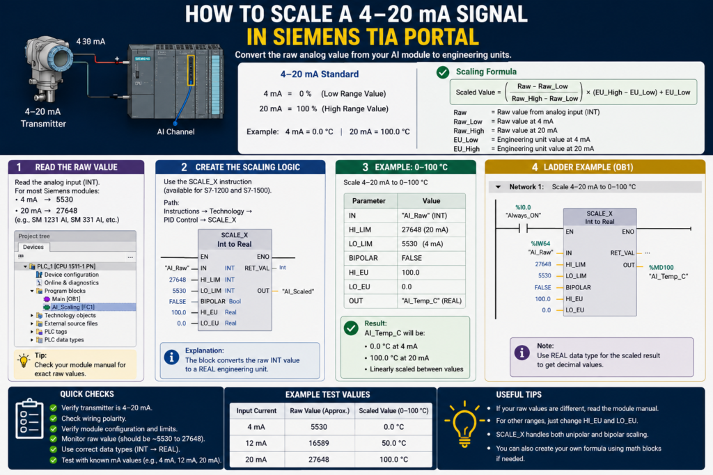
A pressure transmitter is wired to the PLC, the analog channel is configured, and TIA Portal shows a raw value such as 13,824.
What does that number mean?
It is not pressure, temperature, flow or tank level. It is the digital value produced by the Siemens analog input module after converting the measured current.
To use the signal inside your PLC program, you must convert that raw value into engineering units. In TIA Portal, the usual method is to place a NORM_X instruction before a SCALE_X instruction.
The process is simple once one important detail is understood: the correct raw limits depend on how the analog channel is configured.
What Does a 4–20 mA Signal Represent?
A 4–20 mA transmitter converts a physical measurement into electrical current.
For a pressure transmitter measuring 0 to 10 bar:
- 4 mA represents 0 bar
- 12 mA represents 5 bar
- 20 mA represents 10 bar
The 4 mA starting point is called a live zero. Because the normal minimum is above 0 mA, the control system can distinguish a valid zero measurement from certain wiring or transmitter faults.
A broken loop may produce close to 0 mA, while a healthy transmitter measuring zero pressure should still produce approximately 4 mA.
Understand Siemens Raw Analog Values
Siemens current input modules generally represent their configured nominal measurement range using raw integer values from:
0at the bottom of the configured range27648at the top of the configured range
This means that when the input channel is configured directly as 4–20 mA, the normal representation is:
| Current | Raw value |
|---|---|
| 4 mA | 0 |
| 8 mA | 6912 |
| 12 mA | 13824 |
| 16 mA | 20736 |
| 20 mA | 27648 |
Siemens documentation for current inputs shows that a channel configured for 4–20 mA returns 0 at 4 mA and 27,648 at 20 mA. Values outside the nominal range may indicate underrange, overrange or a diagnostic condition.
This is where many scaling mistakes begin.
What If the Channel Is Configured for 0–20 mA?
Not every Siemens analog input supports a selectable 4–20 mA range. Sometimes a 4–20 mA transmitter is connected to a channel configured as 0–20 mA.
In that situation:
- 0 mA equals raw value 0
- 4 mA equals approximately raw value 5530
- 20 mA equals raw value 27648
The calculation for 4 mA is:
4 ÷ 20 × 27648 = 5529.6
Rounded to an integer, this becomes approximately 5530.
Therefore, two valid scaling arrangements exist:
Channel Configured as 4–20 mA
Use raw limits:
- Minimum: 0
- Maximum: 27648
Channel Configured as 0–20 mA
Use raw limits:
- Minimum: 5530
- Maximum: 27648
Do not use 5530 as the minimum merely because the transmitter is labelled 4–20 mA. First check the measurement range selected in the analog module’s hardware configuration.
Step 1: Configure the Analog Input Channel
Open the PLC device configuration in TIA Portal.
Select the analog input module or signal board, then open the channel properties. Depending on the module, choose:
- Current
- 4–20 mA
Alternatively, select 0–20 mA if that is the only current range supported by the hardware.
Also review:
- Wire-break diagnostics
- Overflow and underflow diagnostics
- Smoothing
- Interference-frequency suppression
- Channel address
Siemens S7-1200 modules differ in their supported ranges, resolution and diagnostic capabilities, so the equipment manual for the exact module number takes priority over a generic example.
Step 2: Create PLC Tags
Create tags for the raw input, normalised value and scaled result.
For example:
| Tag | Data type | Example address |
Pressure_Raw | Int | %IW64 |
Pressure_Normalized | Real | Internal tag |
Pressure_Bar | Real | Internal tag |
Pressure_Fault | Bool | Internal tag |
The hardware input normally arrives as an integer. The normalised and engineering values should generally use the Real data type.
Give the tags meaningful names. A tag called TankPressure_Bar is far easier to understand later than one called AnalogValue1.
Step 3: Add the NORM_X Instruction
The NORM_X instruction converts the raw value into a floating-point value between 0.0 and 1.0.
For a channel configured as 4–20 mA, use:
MIN: 0VALUE:Pressure_RawMAX: 27648- Output:
Pressure_Normalized
The expected results are:
| Raw input | Normalised result |
| 0 | 0.0 |
| 6912 | 0.25 |
| 13824 | 0.5 |
| 20736 | 0.75 |
| 27648 | 1.0 |
Siemens describes NORM_X as the instruction used to map an input value from its defined minimum and maximum range onto a linear normalised scale.
For an input configured as 0–20 mA but connected to a 4–20 mA transmitter, change the MIN parameter to 5530.
Step 4: Add the SCALE_X Instruction
The SCALE_X instruction converts the normalised value into the transmitter’s engineering range.
For a 0–10 bar pressure transmitter, use:
MIN: 0.0VALUE:Pressure_NormalizedMAX: 10.0- Output:
Pressure_Bar
The complete conversion becomes:
Raw input → NORM_X → 0.0 to 1.0 → SCALE_X → 0.0 to 10.0 bar
Siemens recommends this two-stage process for converting analog input values into engineering units: normalise the raw value first, then scale the result into the required physical range.
Example: 0–10 Bar Pressure Transmitter
Assume:
- Transmitter range: 0 to 10 bar
- Signal: 4–20 mA
- Analog channel: configured as 4–20 mA
- Raw input: 13824
The NORM_X result is:
13824 ÷ 27648 = 0.5
The SCALE_X result is:
0.5 × 10 bar = 5 bar
Therefore, a raw value of 13,824 represents approximately 5 bar.
Example: Temperature From −20°C to 80°C
The engineering minimum does not have to be zero.
For a transmitter measuring −20°C to 80°C:
NORM_X
MIN: 0VALUE:Temperature_RawMAX: 27648
SCALE_X
MIN: −20.0VALUE:Temperature_NormalizedMAX: 80.0
At 12 mA, the normalised value is approximately 0.5.
Halfway between −20°C and 80°C is 30°C, so the scaled result should be approximately 30°C.
SCL Scaling Example
The same operation can be written in SCL:
#Pressure_Normalized := NORM_X(
    MIN   := 0,
    VALUE := #Pressure_Raw,
    MAX   := 27648
);

#Pressure_Bar := SCALE_X(
    MIN   := 0.0,
    VALUE := #Pressure_Normalized,
    MAX   := 10.0
);
For a 0–20 mA input channel receiving a 4–20 mA transmitter signal, change the first minimum value:
#Pressure_Normalized := NORM_X(
    MIN   := 5530,
    VALUE := #Pressure_Raw,
    MAX   := 27648
);
Use variables and constants with suitable data types. Accidental integer arithmetic in a custom scaling formula can remove the decimal portion and produce inaccurate results.
The Direct Scaling Formula
The conversion can also be expressed with one formula:
Scaled value = Engineering minimum + ((Raw − Raw minimum) × Engineering span ÷ Raw span)
For a 0–10 bar transmitter on a 4–20 mA configured channel:
Pressure = 0 + ((Raw − 0) × 10 ÷ 27648)
For the same transmitter connected to a 0–20 mA channel:
Pressure = 0 + ((Raw − 5530) × 10 ÷ (27648 − 5530))
The formula is useful when creating a reusable function block, but NORM_X and SCALE_X are usually easier to read and troubleshoot in TIA Portal.
Add Signal Fault Detection
Scaling alone is not enough for a reliable industrial program.
Check for:
- Wire break
- Input underrange
- Input overrange
- Module diagnostic errors
- Invalid raw values
- Transmitter power failure
Some Siemens modules configured for 4–20 mA can detect a wire break when the measured current falls below a defined threshold. The exact raw value and diagnostic behaviour vary by module; on some S7-1200 modules, wire break may be represented by the special value 32767 rather than an ordinary low raw number.
Use the module’s hardware diagnostics where available. Do not rely entirely on code such as Raw < 0 without checking how your specific module reports faults.
A sensible program structure is:
- Read the raw input.
- Evaluate channel diagnostics.
- Confirm that the signal is valid.
- Normalise and scale the value.
- Generate an alarm or substitute value when the signal is invalid.
Do not clamp every invalid value to zero before evaluating it. That can turn a broken transmitter wire into what appears to be a valid empty tank or zero-pressure reading.
Common Scaling Mistakes
Using 5530 With a Channel Already Configured for 4–20 mA
On a true 4–20 mA range, raw zero already represents 4 mA. Using 5530 again shifts the complete measurement.
Using 0 as the Minimum on a 0–20 mA Channel
This makes 4 mA appear as 20% of the engineering range instead of the transmitter’s zero value.
Selecting the Wrong Hardware Range
A current transmitter connected to a voltage-configured input will not scale correctly and may be wired incorrectly.
Scaling the Wrong Input Address
Confirm the channel address in Device View. Do not assume the first channel is always %IW64.
Ignoring Overrange and Wire-Break Values
Values above 27648 are not always valid process measurements. They may represent overshoot, overflow or diagnostic states.
Using INT for the Engineering Result
Pressure, temperature and flow values often need decimals. Store the scaled output as Real.
Quick Commissioning Check
Before accepting the scaling:
- Simulate or apply approximately 4 mA.
- Confirm the engineering value is close to its minimum.
- Apply approximately 12 mA.
- Confirm the result is near the midpoint.
- Apply approximately 20 mA.
- Confirm the result is close to the maximum.
- Disconnect the signal and verify that a fault is detected.
- Check the displayed units on the HMI.
A loop calibrator makes this considerably easier because it can generate known current values without relying on the actual process.
Final Thoughts
Scaling a 4–20 mA signal in Siemens TIA Portal is usually a two-step operation:
- Use
NORM_Xto convert the raw input into a value from 0.0 to 1.0. - Use
SCALE_Xto convert that value into pressure, temperature, level, flow or another engineering unit.
The critical part is choosing the correct raw minimum.
Use 0 when the Siemens channel is configured directly for 4–20 mA. Use approximately 5530 when a 4–20 mA transmitter is being read through a channel configured for 0–20 mA.
Check the hardware configuration first. Otherwise, perfectly written scaling logic can still produce the wrong answer.