At the right-hand end of a control rung, or at the business end of a power circuit, sit the loads — the devices that actually do work. Where contacts and coils express the logic, loads are what the logic controls: the motors, solenoids, lamps, and heaters that turn electrical energy into physical action.
Motors
The motor is the most important load in most industrial systems, drawn as a circle containing ‘M’, sometimes with an indication of its type such as ‘3~’ for three-phase. On a control drawing, a motor may appear as the load at the end of a rung, or its control may be represented by the contactor coil that switches its power, with the motor’s actual power connection shown on a separate power drawing. Reading a motor symbol tells you that here is the machine’s mechanical output, the thing the whole circuit exists to control. Where the motor’s power is switched — by the main contacts of a contactor — and where its control decisions are made are often on different drawings, connected by the shared contactor label, which is a key relationship covered later.
Solenoids, lamps, and other outputs
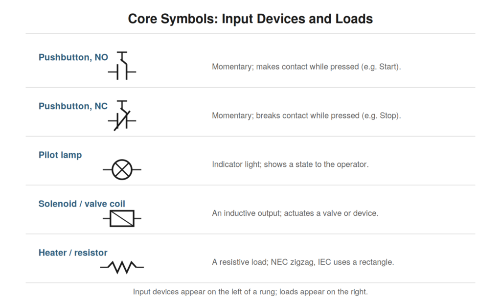
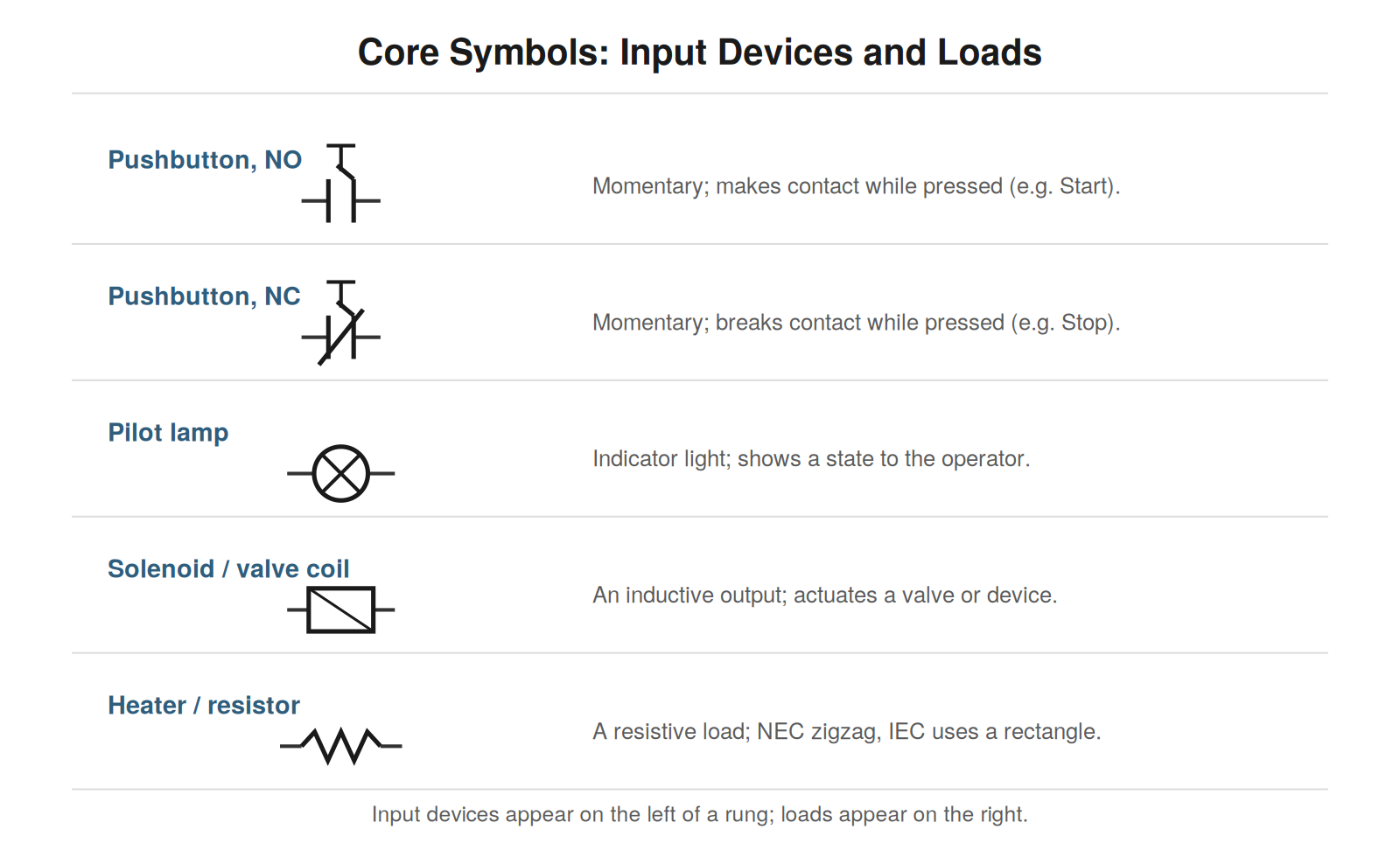
Beyond motors, several common loads each have their symbol. A solenoid — an electromagnetic coil that actuates a valve or mechanism — is drawn as a coil or box, similar to a relay coil but representing a device that produces mechanical motion rather than operating contacts. A pilot lamp, drawn as a circle with a cross, is an indicator light that shows a state to the operator, and reading pilot lamps on a drawing tells you what the machine communicates about its own condition. A heater or resistive load is drawn as a zigzag (NEC) or rectangle (IEC), representing a component that converts current to heat. Each of these is a load — an output the control logic drives — and recognizing them tells you what the circuit acts upon.
Reading a load in its circuit
A load’s meaning comes from its place in the circuit as much as its symbol. A load sits where the circuit’s energy is delivered — at the end of a control rung, downstream of all the conditions that control it, or in the power path downstream of the switching and protection. Reading a load in context means seeing what conditions must be satisfied for it to be energized: for a load at the end of a rung, every contact in series before it must be closed. This connects the load back to the logic — the load does its work only when the logic upstream permits, and reading the circuit means seeing both the load and the chain of conditions that governs it. The load is the purpose; the logic before it is the set of conditions on that purpose being fulfilled.
Distinguishing loads from coils
A subtle but important reading distinction is between a coil (which operates contacts as part of the logic) and a load (which does physical work as the purpose of the circuit), because both can appear at the right end of a rung and they play different roles. A relay coil at the end of a rung is part of the control logic — energizing it operates contacts elsewhere that continue the logic. A load like a lamp, solenoid, or heater at the end of a rung is an endpoint — energizing it produces a physical result, not further logic. Reading a rung, recognizing whether its right-hand element is a coil (logic continues through its contacts) or a load (the rung’s purpose is fulfilled) tells you whether to follow the effect further or recognize an endpoint. A contactor coil is an interesting hybrid: it is a coil (operating contacts that switch motor power) but its purpose is to run the motor, so it bridges logic and load. Reading these distinctions clarifies the structure of the control logic and where its various threads end in physical action.
Reading exercise: tracing conditions on a load
To connect loads back to the logic that controls them, practice tracing the conditions on a load — starting from the load and listing every condition upstream that must be satisfied for it to be energized. Pick a load at the end of a rung and read backward: this load is energized when every series contact before it is closed, so list them — this contact, that permissive, this interlock — and for any that are operated by other coils, note what controls those. The result is a complete statement of what must be true for the load to operate. This exercise reverses the usual left-to-right reading and builds the troubleshooting skill of starting from a non-working output and enumerating its conditions, which is the first step of the reading-based troubleshooting method. Practicing it on various loads — motors, lamps, solenoids — builds fluency in seeing any output as the endpoint of a chain of conditions, and in listing those conditions quickly, which is exactly what you must do when that output fails and you need to find which condition is unmet.
Indicator circuits and what they tell you
Indicator circuits — pilot lamps showing a machine’s state — are worth reading carefully, because they reveal what the machine communicates and because they are useful diagnostic aids in their own right. A pilot lamp is driven by a contact of some device, so reading the lamp’s rung tells you what state it indicates: a lamp driven by a normally-open contact of the run contactor lights when the motor runs; a lamp driven by a fault relay lights when a fault is present. Reading these tells you what each indicator means, which helps you interpret the machine’s signals during operation and troubleshooting. Moreover, the indicators are diagnostic aids: if a run lamp is lit, the run contactor is energized (its contact closed the lamp circuit), which tells you something without any measurement. Reading the indicator circuits lets you use the lamps as free status information — each lit or unlit lamp confirming the state of whatever drives it. Understanding what each indicator reflects, by reading its driving contact, turns the machine’s own lights into a diagnostic panel you can read at a glance.
Reading output devices for their failure modes
Reading a load with its failure modes in mind helps you troubleshoot when the load itself is suspect, because different loads fail in characteristic ways that reading the circuit helps you assess. A motor can fail open (a burned-out winding), a solenoid coil can fail open or short, a lamp can burn out, a heater can fail open. Reading the circuit tells you what should reach the load and what the load should do when energized, so comparing the load’s actual behavior to this expectation helps determine if the load has failed. If the drawing says the load should be energized (all conditions met, power reaching it) but the load does nothing, the load itself may have failed. Reading the circuit establishes the expectation — under these conditions, this load should operate — against which the load’s actual behavior is judged. This is how reading extends to diagnosing the output devices themselves, not just the logic controlling them: the reading tells you when the load should operate, and if it does not operate when it should, with power confirmed present, the load is the suspect. Reading the circuit around the load is what lets you conclude the load has failed rather than something upstream.
Case: power present but the load dead
A revealing case is a load that is dead despite power being present at it, which reading the circuit helps resolve to the load itself. A load was not operating, and reading the circuit showed all its conditions met and power reaching it — measured and confirmed present at the load’s terminals. Yet the load did nothing. Reading the circuit had established that the load should operate: conditions met, power present. The load’s failure to operate despite this pointed to the load itself as failed — a burned-out coil, an open heater, a failed motor winding. Reading the circuit was what allowed this conclusion, by confirming everything upstream was correct and power was present, leaving the load as the only remaining suspect. Replacing the failed load restored operation. This case shows how reading the circuit isolates a failed load: by confirming, through the reading, that all conditions are met and power reaches the load, the reading eliminates everything upstream and points to the load itself. Without the reading, you could not be sure the fault was the load rather than something upstream; with it, you confirm upstream is good and conclude the load has failed. Reading around the load is what turns ‘the load does not work’ into the specific diagnosis ‘the load itself has failed, because everything upstream is confirmed good.’
Reading outputs as the purpose of the circuit
A useful perspective in reading any circuit is to see the outputs as its purpose — the reason the circuit exists — and to read the rest of the circuit as the conditions and logic serving those outputs. The circuit exists to control its outputs: to run the motor, actuate the solenoid, light the lamp, energize the heater. Everything else — the inputs, the logic, the conditions — exists to determine when and how the outputs operate. Reading with this perspective, you start from the outputs (the purpose) and understand the rest as serving them, which organizes the reading around the circuit’s actual goals. This is why troubleshooting starts from the affected output: the output is the purpose, and a fault is the purpose not being achieved, so you start there and read back through the serving logic to find why. Seeing outputs as the circuit’s purpose gives the reading a natural organization — purpose first, then the logic serving it — that matches how the circuit is actually structured and how faults are actually approached. Reading a circuit as ‘these are the outputs it exists to control, and this is the logic that controls them’ is a clarifying perspective that keeps the reading oriented around the circuit’s real purpose, which is to operate its outputs correctly under the right conditions.