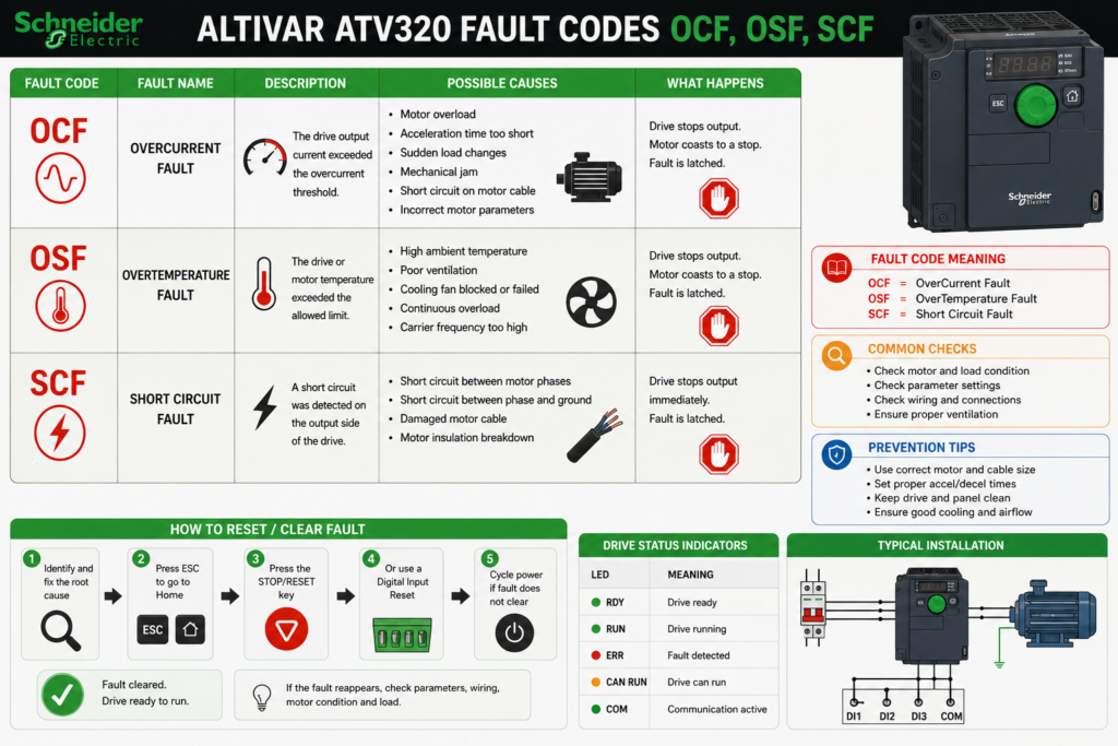
An Altivar ATV320 stops and displays OCF, OSF or SCF.
Resetting the drive may clear the screen, but it does not remove the reason the fault occurred. A jammed conveyor, damaged motor cable or unstable incoming supply will usually trip the drive again as soon as the motor restarts.
These three fault groups point to different parts of the installation:
- OCF: Excessive motor current
- OSF: Excessive incoming supply voltage
- SCF: Short circuit, earth leakage or drive power-stage problem
The exact timing of the trip is often as useful as the code itself. Record whether it occurred during power-up, acceleration, steady running, deceleration or immediately after a motor cable was changed.
Safety warning: An ATV320 contains hazardous voltage after incoming power is disconnected. Isolate all power sources, including external control power, lock the disconnect open, wait at least 15 minutes and verify that the DC bus between PA/+ and PC/− is below 42 V before touching the drive, motor or output wiring. The drive’s LEDs are not proof that the DC bus is discharged.
Quick Fault-Code Chart
| Code | Meaning | Most likely area |
|---|---|---|
| OCF | Overcurrent | Motor parameters, mechanical load, acceleration or motor sizing |
| OSF | Supply mains overvoltage | Incoming L1/L2/L3 voltage or power-quality disturbance |
| SCF1 | Motor short circuit | Motor cable, motor insulation or drive output |
| SCF3 | Ground short circuit | Earth leakage, grounded motor cable or motor winding |
| SCF4 | IGBT short circuit | Drive power stage |
| SCF5 | Load/output short circuit during the drive’s load test | Motor cable, motor or drive hardware |
The ATV320 manual treats SCF as a family of faults, so record the complete code. SCF1, SCF3, SCF4 and SCF5 do not have identical causes or repair procedures.
Check the Fault History Before Resetting
Do not erase the evidence immediately.
With the ATV320 graphical keypad, open:
Drive Menu
→ Monitoring
→ Diagnostics
→ Fault History
The fault history stores the eight most recent detected faults, with the newest shown first. Selecting a fault displays operating information captured when it occurred. The same history can be reviewed in SoMove under the error-detection section.
Record:
Exact fault code:
Motor speed:
Motor current:
DC-bus voltage:
Drive status:
Fault occurred during:
Recent electrical or mechanical work:
A fault that appears only during acceleration should be approached differently from one that appears while the drive is idle.
OCF: Overcurrent Fault
OCF means the ATV320 detected excessive output current.
Schneider lists three main causes:
- Incorrect motor-control or drive settings
- Excessive load or inertia
- Mechanical locking
Recommended checks include the configured motor parameters, motor and drive sizing, the driven mechanism, current-limit setting and switching-frequency setting.
Common Causes of OCF
Typical causes include:
- Conveyor, pump or gearbox mechanically jammed
- Acceleration time too short for the load
- Incorrect motor nameplate data
- Motor or drive undersized for the application
- Sudden process-load increase
- Damaged bearings
- Seized brake
- Incorrect motor-control mode
- Poor autotuning result
- Motor connected incorrectly in star or delta
- Current limit set incorrectly
- Motor cable or winding beginning to fail
OCF During Acceleration
When OCF appears shortly after the Run command, begin with the mechanical load and acceleration conditions.
Check whether:
- The shaft turns freely with power isolated
- A mechanical brake releases correctly
- The conveyor or machine is blocked
- The load starts under excessive pressure or tension
- The acceleration ramp was recently shortened
- The motor is wired for the available voltage
- The drive contains the correct motor nameplate data
Review parameters such as:
Motor rated power
Motor rated voltage
Motor rated current
Motor rated frequency
Motor rated speed
Motor thermal current
Incorrect motor data can cause poor flux and current control. Schneider specifically recommends checking the motor-control parameters and the sizing of the drive, motor and load when OCF occurs.
OCF While Running at Constant Speed
A trip after several seconds or minutes often points toward the process or mechanical system.
Inspect:
- Actual motor current on all phases
- Gearbox and bearing temperature
- Product buildup
- Pump blockage or closed valve
- Conveyor tension
- Motor cooling
- Brake drag
- Load changes during the production cycle
Compare the displayed current with the motor nameplate current and the expected machine load.
Do not assume the drive is defective because the motor current is high. The drive may simply be reporting that the machine is asking for more torque than the system can provide safely.
Be Careful With the Current-Limit Setting
The ATV320 may display flashing current values when output current reaches the configured current limit.
Do not automatically increase the limit to stop OCF.
Schneider’s current manual includes reducing the current-limit parameter among possible OCF remedies, while an ATV320 technical FAQ notes that a carefully assessed increase may help where the limit was configured too low. These recommendations apply to different situations. Measure the actual current and verify the drive, motor and machine limits before changing the setting.
Raising the limit on a mechanically jammed conveyor does not repair the conveyor. It merely allows the drive to push harder against the fault.
Advanced OCF Checks
Schneider notes that OCF can sometimes be produced by conditions other than an ordinary mechanical overload, including:
- Excessive motor magnetising current
- Motor saturation
- Motor inductance lower than the value identified by the drive
- Motor asymmetry
- Incorrect or unsuitable autotuning data
For intermittent cases, SoMove’s fast oscilloscope can monitor values such as motor current, short-circuit current threshold and motor speed around the moment of the trip.
How to Fix OCF
Use this sequence:
- Isolate the machine and check for mechanical locking.
- Verify that the motor turns freely.
- Compare motor nameplate data with the ATV320 configuration.
- Confirm star/delta motor connections.
- Check actual current during acceleration and normal running.
- Review the acceleration ramp and current-limit setting.
- Check drive and motor sizing.
- Repeat or review autotuning only when permitted by the machine procedure.
- Inspect the motor cable and motor when current appears unbalanced or abnormal.
- Reset only after the cause is corrected.
OSF: Supply Mains Overvoltage
OSF means the voltage on the incoming supply is too high or the mains supply is disturbed.
Schneider’s ATV320 manual identifies:
- Supply voltage too high
- Disturbed mains supply
The primary corrective action is to check the incoming supply voltage.
Common Causes of OSF
Possible causes include:
- Drive connected to the wrong supply voltage
- Transformer tap set too high
- High utility voltage
- Unstable generator supply
- Capacitor-bank switching
- Line transients
- Poor neutral or distribution condition elsewhere in the installation
- Another load producing disturbances on the common supply
- Incorrect drive voltage class for the installation
Measure All Incoming Phases
Measure at the drive input terminals:
L1 to L2
L2 to L3
L1 to L3
Compare the measurements with the exact ATV320 model and its permitted supply range.
Do not test only at an upstream distribution board. A wiring or transformer problem may produce different conditions at the drive terminals.
An ordinary multimeter may not capture a brief overvoltage spike. When OSF occurs intermittently and steady readings appear normal, a power-quality recorder may be required to capture the event. Schneider identifies both sustained high line voltage and line-side spikes or disturbances as possible causes.
OSF Is Not the Same as OBF
This distinction saves a lot of unnecessary troubleshooting.
OSF
Supply mains overvoltageOSF usually directs attention toward the incoming L1/L2/L3 supply.
OBF
DC-bus overvoltageOBF is commonly associated with:
- Rapid deceleration
- High-inertia load
- Overhauling load
- Regenerative energy returning from the motor
- High supply voltage
For OBF, Schneider recommends actions such as extending the deceleration time, using a suitable braking resistor, checking the supply and activating deceleration-ramp adaptation when compatible with the application.
A useful practical distinction is:
Fault at power-up or while idle → investigate OSF and incoming power
Fault during rapid stopping     → investigate OBF and regeneration
Do not install a braking resistor to fix a genuine high-voltage incoming supply.
How to Fix OSF
- Record when the fault occurs.
- Verify the drive’s voltage class.
- Measure all three phase-to-phase voltages.
- Check transformer tap settings.
- Compare readings during different production conditions.
- Check whether capacitor banks or large loads switch near the fault time.
- Use a power-quality recorder for short intermittent events.
- Correct the supply problem before resetting the drive.
SCF: Short-Circuit Faults
SCF should never be treated as one generic code.
The full suffix identifies what the drive detected:
SCF1 — Motor short circuit
SCF3 — Ground short circuit
SCF4 — IGBT short circuit
SCF5 — Load or output short circuit during the load test
Repeatedly resetting an SCF fault can damage the drive and expose personnel to a real insulation or earth-fault hazard.
SCF1: Motor Short Circuit
SCF1 means the drive detected a short circuit or grounding condition at its output.
Schneider recommends checking the motor cable, motor insulation, switching frequency and the suitability of any motor choke. It also lists speed-loop, brake and restart-time settings among the items that may need review in particular applications.
Common SCF1 causes
- Phase-to-phase short in the motor cable
- Damaged motor winding
- Loose copper strands at the drive terminals
- Cable crushed against machinery
- Moisture inside the motor terminal box
- Faulty output contactor
- Motor cable insulation damaged by heat or abrasion
- Incorrect motor parameters
- Excessive motor magnetising current
- Motor asymmetry
- Drive output-stage failure
Inspect the output circuit
With the drive safely isolated, inspect:
U/T1
V/T2
W/T3
Motor cable
Motor terminal box
Output contactor, where fitted
Junction boxes
Cable glands
Look for:
- Burned terminals
- Carbon tracking
- Loose strands
- Damaged insulation
- Moisture
- Incorrect links in the motor terminal box
- Contactors switching incorrectly
SCF3: Ground Short Circuit
SCF3 indicates a significant current path from the drive output to earth.
Schneider also notes that high earth-leakage current can occur when several motors are connected in parallel. Recommended checks include the motor, output cable, insulation, switching frequency, motor choke and control settings.
Common SCF3 causes
- Motor winding leaking to earth
- Damaged motor cable touching grounded metal
- Moisture in the motor
- Contamination in a junction box
- Cable gland cutting into insulation
- Several parallel motors creating excessive leakage
- Very long motor cable
- Incorrect or missing output reactor where required
- Internal drive power-stage problem
An insulation fault may worsen as the motor heats. A motor can therefore run correctly when cold and produce SCF3 after several minutes.
Disconnect the Drive Before Insulation Testing
Never apply a megohmmeter test voltage through the ATV320 output terminals.
Disconnect the motor leads from the drive before testing the motor or motor cable. Test the cable and motor separately where possible, using a test voltage permitted by the motor manufacturer and site procedure. Schneider’s ATV320 guidance requires the motor to be disconnected from the drive before insulation-resistance testing.
A useful separation procedure is:
Drive disconnected from cable
        ↓
Test cable conductors to earth
        ↓
Disconnect cable at motor
        ↓
Test motor windings to earth separately
This helps determine whether the problem is in the motor or cable instead of condemning both.
SCF4: IGBT Short Circuit
SCF4 indicates that the ATV320 detected a problem involving its power components or IGBT output stage.
Schneider’s prescribed action is to contact Schneider Electric technical support.
Before concluding that the drive has failed, qualified personnel should still inspect the external motor circuit and verify that no cable or motor fault caused the event.
When SCF4 returns with the motor circuit properly isolated, the drive is a strong suspect. Do not continue repeatedly powering it up.
SCF5: Load Short Circuit
SCF5 indicates a short circuit detected at the drive output during the internal load-detection sequence.
Schneider recommends checking the cables and motor insulation. If the external circuit is healthy and the fault remains, technical support or drive replacement may be required.
Separating an External Fault From a Drive Fault
A practical diagnostic sequence is:
- Record the complete SCF code.
- Isolate all power and verify the DC bus is discharged.
- Inspect the drive output terminals and motor cable.
- Disconnect the motor leads from the drive.
- Test the motor and cable separately.
- Correct any insulation or wiring fault.
- Where permitted by Schneider’s procedure, perform an open-circuit drive test.
- Restore all temporarily changed parameters afterward.
- Replace or repair the drive when the fault remains with the external output circuit removed.
Schneider’s SCF3 guidance notes that if the fault remains during a correctly performed test with the motor circuit disconnected, the drive itself may be defective.
How to Reset an ATV320 Fault
Correct the cause first and remove the Run command.
The available reset method depends on the fault and the drive configuration.
Method 1: Cycle the Power
For faults requiring a power reset:
- Remove the Run command.
- Disconnect all power sources.
- Wait for the display to go blank.
- Where electrical work is being performed, wait at least 15 minutes and verify that the DC bus is below 42 V.
- Correct the fault.
- Restore power.
- Restart the machine under controlled conditions.
Schneider classifies certain faults as nonresettable until power has been removed and restored. Its safety procedure requires isolation, lockout, waiting and direct DC-bus voltage verification.
Method 2: Use a Logic Input for Fault Reset
A digital input can be assigned as the fault-reset command.
The parameter path is:
CONF
→ FULL
→ FLT-
→ RST-
Assign the required input under Fault Reset Assign. Once the original fault condition is gone, changing the assigned input to 1 issues a reset.
The input should provide a deliberate pulse. It should not remain permanently active to hide repeating faults.
Method 3: Use the Graphical Keypad
The STOP/RESET key on the graphical display terminal can perform a manual fault reset when the terminal is the active command channel and the fault is eligible for manual reset.
Confirm that no active Run command remains before pressing it.
OCF, SCF1 and SCF3 Reset Behaviour
By default, OCF, SCF1 and SCF3 generally require a power reset when:
HrfC = NoWhen the expert-level parameter is deliberately configured as:
HrfC = Yesthese faults can be included in manual reset through the assigned fault-reset input after the cause is removed.
Do not enable this merely because power cycling is inconvenient. A short-circuit fault that can be reset more easily is still a short-circuit fault.
OSF Reset Behaviour
After the supply voltage returns to an acceptable level, OSF can be cleared through:
- Automatic fault reset, where properly configured
- The assigned manual fault-reset command
- A suitable power cycle
Schneider lists both automatic and manual reset options for OSF once the cause has disappeared.
Be Careful With Automatic Restart
Automatic fault reset and automatic restart are not the same as repairing the fault.
When the original Run command remains present, resetting or restarting the drive can cause immediate motor operation. Schneider warns that restart functions may cause the equipment to operate immediately and must be used only where unintended movement cannot create a hazard.
Do not use automatic restart to keep a machine running through:
- Recurring OCF trips
- Unstable mains voltage
- Ground faults
- Motor-cable damage
- Internal drive faults
Repeated automatic attempts can worsen equipment damage and make troubleshooting more difficult.
Fast Troubleshooting Checklist
OCF — OVERCURRENT
[ ] Determine whether fault occurs during acceleration or running
[ ] Check machine for mechanical locking
[ ] Verify motor nameplate parameters
[ ] Confirm star/delta motor connection
[ ] Measure actual motor current
[ ] Check acceleration conditions
[ ] Review current limit without blindly increasing it
[ ] Verify motor and drive sizing
[ ] Inspect motor cable and motor

OSF — SUPPLY MAINS OVERVOLTAGE
[ ] Confirm exact ATV320 voltage class
[ ] Measure L1-L2, L2-L3 and L1-L3
[ ] Check transformer taps
[ ] Look for line transients and capacitor switching
[ ] Use a recorder for intermittent spikes
[ ] Distinguish OSF from braking-related OBF

SCF — SHORT CIRCUIT
[ ] Record complete code: SCF1, SCF3, SCF4 or SCF5
[ ] Inspect U/T1, V/T2 and W/T3 terminals
[ ] Check motor cable for damage and moisture
[ ] Disconnect drive before insulation testing
[ ] Test motor and cable separately
[ ] Check output contactors and junction boxes
[ ] Investigate drive hardware if fault remains disconnected
Final Thoughts
The three fault groups point in different directions:
OCF
→ Excessive current, motor setup or mechanical load
OSF
→ Incoming supply voltage or power qualitySCF
→ Motor cable, motor insulation, earth leakage or drive power stageRecord the operating conditions and exact code before resetting anything.
For OCF, begin with the load, motor data and actual current.
For OSF, measure the incoming supply and distinguish it from regenerative DC-bus overvoltage.
For SCF, stop resetting and test the motor circuit properly. The suffix matters.
A fault reset should be the last step of the repair—not the first troubleshooting method.