AC servomotors are designed for applications that require accurate control of speed, position and torque. Although servo systems can appear complicated, the motor itself is built around two familiar components:
- The stator
- The rotor
The stator remains stationary and produces a rotating magnetic field. The rotor sits inside the stator and turns in response to that field.
Two main types of AC motors are used in servo applications:
- Synchronous motors
- Induction, or asynchronous, motors
Both use a similar stator construction, but their rotors operate differently.
The Servomotor Stator
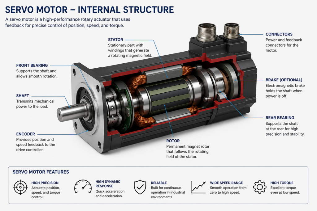
The stator is the stationary outer section of the motor.
Insulated wire is wound into coils and placed inside slots around the motor housing. These coils are known as the stator windings.
In a three-phase motor, the windings are divided into three phase groups:
Phase A
Phase B
Phase C
The phase windings are positioned electrically 120 degrees apart. When the servo drive supplies three-phase current to these windings, their magnetic fields combine to produce one rotating magnetic field.
The number and arrangement of the windings determine the number of motor poles.
For example:
- A two-pole motor has one north and one south magnetic pole.
- A four-pole motor has two north and two south pole pairs.
- A motor with more poles has a lower synchronous speed at the same electrical frequency.
How a Rotating Magnetic Field Is Created
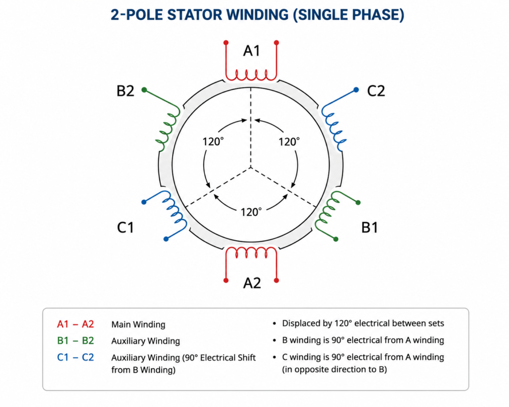
The current in each phase winding changes continuously with the applied AC waveform.
As the direction and magnitude of the current change, the magnetic polarity and strength produced by each winding also change.
At one moment:
- Phase A may have no current.
- Phase B may carry current in the negative direction.
- Phase C may carry current in the positive direction.
A short time later, the current relationships change. Different windings become magnetic north and south poles.
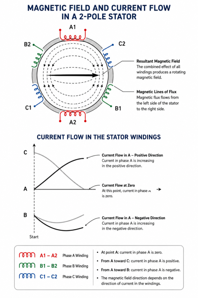
Because the three phases are displaced by 120 electrical degrees, the combined magnetic field does not simply switch on and off. It moves continuously around the inside of the stator.
This movement creates the rotating magnetic field that pulls or induces the rotor into motion.
Magnetic Flux and the V/Hz Relationship
The strength of the stator magnetic field is related approximately to the ratio between applied voltage and frequency:
Magnetic flux ∝ Voltage ÷ FrequencyThis relationship is commonly called the volts-per-hertz, or V/Hz, relationship.
Increasing voltage while keeping frequency constant increases magnetic flux. Reducing frequency without reducing voltage also increases flux.
Excessive magnetic flux can saturate the motor’s magnetic material and cause:
- High current
- Excessive heating
- Poor control
- Motor damage
Servo drives therefore regulate motor voltage and current as operating frequency changes.
At low speeds, modern servo drives use controlled current and feedback-based algorithms rather than relying only on a simple fixed V/Hz relationship.
Synchronous Speed
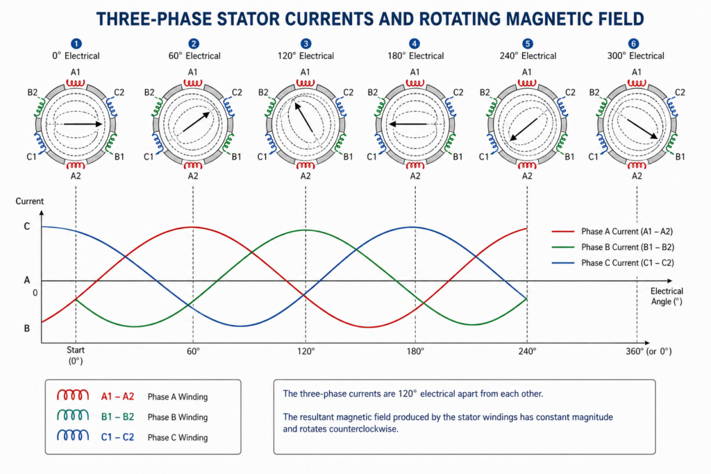
The rotating stator field turns at a speed known as synchronous speed.
It is calculated using:
Ns = 120 × F ÷ PWhere:
Nsis synchronous speed in revolutions per minuteFis electrical frequency in hertzPis the number of motor poles
For a two-pole motor operating at 60 Hz:
Ns = 120 × 60 ÷ 2
Ns = 3,600 rpm
For a four-pole motor at the same frequency:
Ns = 120 × 60 ÷ 4
Ns = 1,800 rpm
Increasing the frequency increases the speed of the rotating field. Increasing the number of poles reduces it.
A servo drive controls motor speed by changing the frequency and phase of the current supplied to the stator windings.
The Synchronous Servomotor Rotor
A synchronous servomotor rotates at the same average speed as the stator’s rotating magnetic field.
Many modern synchronous servomotors use permanent magnets mounted on or embedded inside the rotor.
These are commonly high-strength rare-earth magnets.
The permanent-magnet rotor creates its own magnetic field. When the stator is energized, the rotor’s magnetic poles interact with the rotating stator field:
- Opposite magnetic poles attract.
- Similar magnetic poles repel.
- The rotor follows the moving stator field.
In normal controlled operation, the rotor remains synchronized with the magnetic field produced by the drive.
Unlike an induction motor, a permanent-magnet synchronous motor does not require rotor slip to produce torque.
Why Permanent-Magnet Rotors Are Used
Permanent-magnet synchronous motors are widely used in servo applications because they can provide:
- Low rotor inertia
- Fast acceleration
- Fast deceleration
- High torque relative to motor size
- Accurate speed control
- Efficient operation
- Strong low-speed torque
Low rotor inertia is especially valuable in machines that must change direction or speed rapidly.
Examples include:
- Packaging machinery
- Robotic axes
- CNC equipment
- Pick-and-place systems
- Printing machines
- Electronic assembly equipment
A lighter rotor requires less torque to accelerate, allowing the motor to respond quickly to commands from the servo drive.
Surface-Mounted and Internal Permanent Magnets
Permanent magnets may be installed in different ways.
Surface-mounted magnets
The magnets are attached to the outside surface of the rotor.
This construction can provide:
- Low rotor inertia
- Simple rotor geometry
- Fast dynamic response
However, the magnets must be mechanically secured against high rotational forces.
Interior permanent magnets
The magnets are embedded inside the rotor material.
This design can provide:
- Stronger mechanical protection
- Better operation at high rotational speeds
- Additional reluctance torque
- A wider useful speed range
The exact construction depends on the motor’s intended speed, torque and dynamic-performance requirements.
Induction Servomotor Rotor
An induction servomotor uses a different rotor design.
Instead of permanent magnets, it normally uses conductive rotor bars connected at both ends, forming a squirrel-cage structure.
The stator’s rotating magnetic field moves relative to the rotor conductors. This relative movement induces electrical current in the rotor.
The induced current creates its own magnetic field, which interacts with the stator field and produces torque.
The rotor must rotate slightly slower than the stator field for induction to occur. This speed difference is called slip.
Therefore:
Synchronous motor:
Rotor follows the rotating field synchronously

Induction motor:
Rotor operates below synchronous speed under load
Induction motors are robust and do not require permanent magnets, but permanent-magnet synchronous motors are frequently preferred where very fast response and high torque density are required.
Why Rotor Position Matters
The motor must generate magnetic force in the correct direction to produce controlled torque.
In a servo system, the drive needs to know the rotor’s position relative to the stator magnetic field.
Servo motors commonly use feedback devices such as:
- Incremental encoders
- Absolute encoders
- Resolvers
The drive uses this feedback to control the timing and magnitude of current in the stator phases.
When the current is correctly aligned with rotor position, the drive can control:
- Direction
- Torque
- Speed
- Position
Without accurate rotor-position information, a permanent-magnet servo motor may produce weak, unstable or incorrectly directed torque.
Pole Count and Servo Operation
The number of poles influences the relationship between electrical frequency and mechanical speed.
A motor with more poles requires a higher electrical frequency to reach the same mechanical speed.
For example, to operate at 3,000 rpm:
Two-pole motor:
Lower electrical frequency required

Eight-pole motor:
Higher electrical frequency required
Servo drives are designed to generate the required frequency electronically, so they are not limited to fixed 50 Hz or 60 Hz mains operation.
The motor’s pole count, feedback resolution and drive control algorithm are selected together to provide the required machine performance.
How the Servo Drive Controls the Motor
The servo drive converts incoming electrical power into precisely controlled motor current.
It continually adjusts the three motor phases according to:
- Position command
- Speed command
- Torque demand
- Rotor feedback
- Motor parameters
- Current measurements
A simplified control sequence is:
Controller sends motion command
↓
Servo drive calculates required torque
↓
Drive energizes the stator windings
↓
Stator produces a rotating magnetic field
↓
Rotor follows the field
↓
Encoder reports actual movement
↓
Drive corrects any error
This closed-loop correction allows a servomotor to maintain accurate motion even when machine load changes.
Synchronous and Induction Servomotors Compared
| Characteristic | Synchronous servo motor | Induction servo motor |
|---|---|---|
| Rotor construction | Usually permanent magnets | Conductive squirrel-cage rotor |
| Rotor speed | Synchronized with rotating field | Slightly below synchronous speed |
| Slip required | No normal torque-producing slip | Yes |
| Rotor losses | Relatively low | Current is induced in rotor |
| Rotor inertia | Often low | Usually higher |
| Torque density | High | Generally lower |
| Dynamic response | Very fast | Good, but often slower |
| Common servo use | Precision motion systems | Higher-power or specialized applications |
Both motor types can be controlled accurately with suitable drives and feedback systems.
The best choice depends on required speed, torque, inertia, cost and operating environment.
Common Servomotor Construction Problems
Servomotor performance can be affected by:
- Damaged stator windings
- Phase-to-phase insulation failure
- Magnet damage or demagnetization
- Bearing wear
- Loose encoder coupling
- Incorrect feedback alignment
- Rotor imbalance
- Motor cable faults
- Incorrect drive motor parameters
A motor may still rotate while producing poor torque, excessive current or unstable position control.
When troubleshooting, inspect the complete system rather than assuming the drive is responsible for every motion fault.
Final Thoughts
The operating principle of an AC servomotor begins with the stator.
Three-phase stator windings create a rotating magnetic field. The speed of this field depends on the electrical frequency and the number of motor poles.
A synchronous permanent-magnet rotor follows the rotating field at synchronous speed. An induction rotor develops torque through induced current and operates with some slip.
Permanent-magnet synchronous motors are especially suitable for servo applications because their low rotor inertia and high torque density allow rapid, precise movement.
Although modern servo drives use advanced electronics and control algorithms, the physical foundation remains straightforward:
Controlled stator current
↓
Rotating magnetic field
↓
Rotor torque
↓
Mechanical motion
Understanding that relationship makes servo tuning, motor selection and motion-system troubleshooting much easier.