You connect a 0–10 V sensor to a Siemens PLC and open a watch table. Instead of seeing 5.0 V, the input shows 13824.
At full scale, it displays 27648.
These numbers can look strange when you first work with Siemens analog modules. Why does the value stop at 27,648 instead of 32,767? Does 27,648 mean the module has 27,648 measurement steps? And why does a 4–20 mA input sometimes begin at zero?
The key is simple: Siemens converts the physical voltage or current into a standardised integer representation. Your program must then convert that raw number into engineering units.
What Is an Analog Raw Value?
An analog sensor produces a continuously changing electrical signal, such as:
- 0–10 V
- ±10 V
- 0–20 mA
- 4–20 mA
The PLC cannot directly process “7.4 volts” or “13.8 milliamps.” Its analog-to-digital converter measures the signal and stores the result as an integer.
For many Siemens S7 analog modules, the normal rated range is represented as:
0 to 27648for unipolar current and voltage ranges-27648 to +27648for bipolar voltage ranges
Values outside the normal range may represent overshoot, undershoot, overflow, underflow or a diagnostic condition.
Why Does Siemens Use 27648?
A Siemens analog value is commonly stored in an INT, which can represent values from −32,768 to +32,767.
Siemens does not use the entire positive INT range for the normal measurement span. Instead, 27648, or hexadecimal 6C00, represents the upper end of the rated analog range.
The remaining values above 27,648 provide space for overrange and overflow information.
For example, a Siemens S7-1200 integrated 0–10 V input may use:
| Raw value | Meaning |
|---|---|
| 0 | 0 V |
| 27648 | 10 V, top of rated range |
| 27649–32511 | Overshoot range |
| 32512–32767 | Overflow range |
This allows the PLC to distinguish a normal full-scale measurement from a signal that has exceeded the configured measuring range.
0–10 V Raw Values
For an input configured as 0–10 V:
| Input voltage | Raw value |
| 0 V | 0 |
| 2.5 V | 6912 |
| 5 V | 13824 |
| 7.5 V | 20736 |
| 10 V | 27648 |
The relationship is linear.
A raw value of 13824 is exactly halfway between 0 and 27,648, so it represents approximately 5 V.
The voltage can be calculated with:
Voltage = Raw value × 10 ÷ 27648
For example:
13824 × 10 ÷ 27648 = 5 V
0–20 mA Raw Values
For a channel configured as 0–20 mA:
| Loop current | Raw value |
| 0 mA | 0 |
| 5 mA | 6912 |
| 10 mA | 13824 |
| 15 mA | 20736 |
| 20 mA | 27648 |
The conversion formula is:
Current in mA = Raw value × 20 ÷ 27648
A raw value of 20736 therefore represents:
20736 × 20 ÷ 27648 = 15 mA
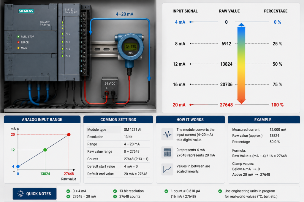
4–20 mA Raw Values
The behaviour of a 4–20 mA signal depends on the range selected in the module configuration.
Channel Configured as 4–20 mA
When the input is configured directly for 4–20 mA:
| Loop current | Raw value |
| 4 mA | 0 |
| 8 mA | 6912 |
| 12 mA | 13824 |
| 16 mA | 20736 |
| 20 mA | 27648 |
The module treats 4 mA as the beginning of the normal measurement range and 20 mA as the end. Siemens’ current-representation tables confirm that a configured 4–20 mA input maps 4 mA to zero and 20 mA to 27,648.
This surprises many beginners because they expect 4 mA to produce a positive raw value.
4–20 mA Transmitter on a 0–20 mA Channel
Some modules may be configured for 0–20 mA while receiving a transmitter that outputs 4–20 mA.
In that case:
- 0 mA equals raw 0
- 4 mA equals approximately raw 5530
- 20 mA equals raw 27648
The 4 mA raw value is calculated as:
4 ÷ 20 × 27648 = 5529.6
Rounded to an integer, this is approximately 5530.
Before choosing your scaling limits, always check the measurement range selected in the hardware configuration.
Bipolar Analog Values
A bipolar signal can represent both positive and negative measurements.
For a ±10 V input:
| Input voltage | Raw value |
| −10 V | −27648 |
| −5 V | −13824 |
| 0 V | 0 |
| +5 V | +13824 |
| +10 V | +27648 |
Siemens maps the rated −10 V to +10 V range onto −27,648 to +27,648.
Do not scale a bipolar input using zero as the raw minimum. Doing so would incorrectly interpret every negative measurement.
Scaling Raw Values Into Engineering Units
Suppose a 0–10 V pressure sensor measures 0–16 bar.
The analog input uses:
- Raw minimum: 0
- Raw maximum: 27648
- Engineering minimum: 0 bar
- Engineering maximum: 16 bar
The general formula is:
Engineering value = Engineering minimum + ((Raw − Raw minimum) × Engineering span ÷ Raw span)
For a raw value of 13824:
Pressure = 0 + (13824 × 16 ÷ 27648)
Pressure = 8 bar
Inside TIA Portal, the same conversion is commonly performed using:
NORM_Xto convert the raw value to 0.0–1.0SCALE_Xto convert the normalised result into engineering units
Example Using NORM_X and SCALE_X
For the 0–16 bar pressure transmitter:
NORM_X
MIN: 0VALUE: raw analog inputMAX: 27648
SCALE_X
MIN: 0.0VALUE: normalised resultMAX: 16.0
The signal path becomes:
Raw input → 0.0 to 1.0 → 0.0 to 16.0 bar
Use REAL for the normalised and scaled values when decimal precision is required.
Is 27648 the Resolution of the Module?
No.
The standardised data-word range and the hardware resolution are related concepts, but they are not the same thing.
A module may have 10-bit, 13-bit, 14-bit or 16-bit conversion hardware while still representing its nominal measurement range using values up to 27,648.
For example, Siemens documents an integrated S7-1200 analog input with 10-bit resolution while its full-scale data-word range remains 0–27,648.
With lower-resolution hardware, not every integer between 0 and 27,648 will necessarily appear. The raw value may change in larger increments.
Therefore, seeing 27,648 does not mean the module provides exactly 27,649 unique measurement levels.
What Do Values Above 27648 Mean?
Values immediately above 27,648 generally indicate that the physical signal has moved beyond the configured rated range.
For a 0–10 V S7-1200 input, Siemens documents:
27648: 10 V, maximum rated value27649–32511: signal above the rated range32512–32767: overflow
For current channels, the exact electrical thresholds differ. A configured 4–20 mA input may continue into an overrange region above 20 mA before reporting overflow.
Do not automatically clamp every value above 27,648 to the engineering maximum. First decide whether your application should report:
- Process overrange
- Instrument fault
- Channel overflow
- An invalid measurement
What Do Negative Values Mean?
Negative values can have two completely different meanings.
On a Bipolar Range
Negative raw values are normal and represent a negative voltage or measurement.
On a Unipolar Current Range
Negative values may indicate underrange or a diagnostic condition rather than a valid negative process measurement.
For example, Siemens documents negative underrange values for certain 4–20 mA modules, with still lower special values used for wire-break or underflow indication. The exact behaviour depends on the module.
Always check the manual for the exact CPU, signal board or analog module.
Common Mistakes
Assuming Every Analog Signal Uses 0–27648
Bipolar voltage ranges use negative raw values. Temperature and resistance modules may also have different representations.
Using 5530 as the Minimum for Every 4–20 mA Signal
Use approximately 5530 only when a 4–20 mA transmitter is read through a 0–20 mA configured channel. A true 4–20 mA channel normally uses zero as its nominal raw minimum.
Treating Overrange as a Valid Process Value
A raw value of 30,000 is not simply “more than 100%.” It may need to generate an alarm.
Ignoring Module Diagnostics
Wire break, overflow and channel errors should be checked separately from ordinary scaling.
Using Integer Arithmetic
Integer division may remove decimal values. Convert operands to REAL or use NORM_X and SCALE_X.
Quick Reference Table
| Configured range | Raw minimum | Raw maximum |
| 0–10 V | 0 | 27648 |
| 0–20 mA | 0 | 27648 |
| 4–20 mA | 0 at 4 mA | 27648 at 20 mA |
| ±10 V | −27648 | +27648 |
| 4–20 mA on a 0–20 mA channel | Approx. 5530 | 27648 |
These values describe common Siemens S7 representations. Confirm the tables for your exact hardware before commissioning.
Final Thoughts
The number 27,648 is simply Siemens’ standard upper value for the normal analog measurement range on many modules.
It leaves additional space inside the INT data type for overrange and diagnostic values. It is not automatically the module’s true measurement resolution.
Remember these basic rules:
- Unipolar ranges normally use 0–27,648.
- Bipolar ranges normally use −27,648 to +27,648.
- A configured 4–20 mA channel uses raw zero at 4 mA.
- Values outside the normal range should be evaluated before scaling.
Once you understand the configured range, Siemens analog raw values stop looking mysterious. They become just another number that can be converted into volts, milliamps, pressure, temperature or whatever the process actually measures.