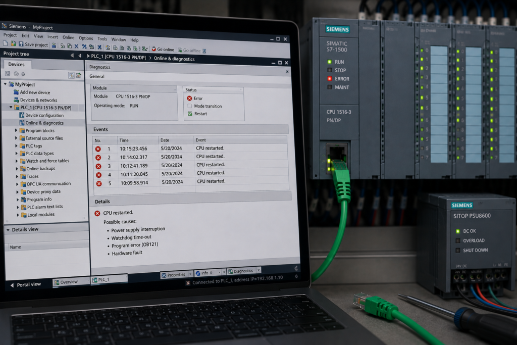
A Siemens PLC that repeatedly restarts can make the entire machine appear unstable.
The CPU begins startup, communications briefly return and then everything disappears again. The HMI may reconnect for a few seconds, remote I/O stations flash their LEDs and outputs appear to initialise repeatedly.
The most common causes are:
- unstable 24 V DC power supply;
- loose power terminal or damaged conductor;
- short circuit pulling down the sensor supply;
- defective CPU hardware;
- fatal firmware error;
- SIMATIC Memory Card or stored-project problem.
Before replacing the CPU, determine what “restarting” actually means.
A PLC that loses power is different from a PLC that remains powered but enters STOP. It is also different from a CPU performing a defect-mode restart after detecting a fatal internal firmware error.
The LED sequence is one of the most valuable clues.
Quick Troubleshooting Table
| Restart pattern | Most likely causes |
|---|---|
| All CPU LEDs go dark before startup begins again | 24 V supply interruption, loose terminal, tripped circuit protector or wiring fault |
| CPU restarts when outputs or contactors energise | Undersized supply, voltage drop, shorted load or shared sensor-supply fault |
| CPU stays powered but changes from RUN to STOP | Program error, cycle-time fault, hardware diagnostic or invalid configuration |
| RUN/STOP, ERROR and MAINT LEDs flash continuously | Fatal CPU firmware error or defective mode |
| CPU repeatedly evaluates the memory card during startup | Invalid card project, damaged card, configuration mismatch or card access problem |
| Restarting began after firmware update | Interrupted update, wrong firmware package or corrupted update files |
| Restarting began after CPU replacement | Old memory-card project, incompatible firmware, protection mismatch or defective replacement |
| Only remote I/O restarts, while the CPU stays in RUN | Remote cabinet power or network problem rather than CPU restart |
| PLC restarts when one sensor cable is connected | Short circuit or overload on sensor supply or common 24 V distribution |
| PLC restarts randomly during vibration | Loose power connector, broken conductor or poor terminal contact |
First Confirm Whether the PLC Is Really Restarting
Technicians often describe several different events as a restart.
The distinction matters because each event has a different troubleshooting path.
True Power Restart
During a real loss of supply:
- CPU LEDs switch off.
- Ethernet LINK disappears.
- HMI and engineering communication stop.
- Power returns.
- CPU performs STARTUP.
- CPU enters RUN or STOP according to its startup configuration.
A true power restart strongly suggests:
- unstable 24 V supply;
- loose L+ or M terminal;
- tripped electronic circuit protector;
- short circuit pulling down the supply;
- failing power supply.
CPU Enters STOP Without Losing Power
In this case:
- CPU LEDs remain illuminated;
- Ethernet LINK may remain active;
- TIA Portal may stay connected;
- RUN/STOP changes to yellow;
- diagnostic buffer records the transition to STOP.
This is not normally a power restart.
Use the diagnostic buffer to inspect the events immediately before the operating-mode transition. Siemens recommends evaluating the entries before the STOP event to determine the original cause.
CPU Performs a Defect-Mode Restart
A fatal internal CPU error can trigger a special restart.
For supported S7-1200 CPUs, Siemens states that the firmware attempts a defect-mode restart after detecting a fatal error. If the restart succeeds, the CPU indicates defective mode by continuously flashing the STOP/RUN, ERROR and MAINT LEDs, and the user program and hardware configuration are not loaded.
That pattern points away from an ordinary field-wiring fault and toward:
- internal CPU hardware;
- corrupted firmware;
- memory failure;
- severe configuration problem.
Remote Device Restarts but CPU Does Not
A missing ET 200 station, drive or HMI can make the system appear to reboot even when the central PLC remains healthy.
Check whether:
- CPU RUN LED stays green;
- only remote-device LINK LEDs disappear;
- diagnostic buffer reports station failure;
- remote cabinet power is cycling.
Do not replace the CPU when only a remote switch or I/O power supply is unstable.
Start With the Diagnostic Buffer
Connect to the CPU before performing another reset or power cycle.
Open:
Online & Diagnostics → Diagnostics → Diagnostic buffer
Look for:
- power-on or startup events;
- transition from RUN to STOP;
- memory-card evaluation error;
- firmware-update failure;
- internal CPU error;
- defective-state message;
- configuration mismatch;
- recurring module failure.
The event sequence matters.
For example:
- Sensor supply short circuit
- Load voltage missing
- CPU power interruption
- CPU startup
The short circuit may be the original problem, while the restart is only the final consequence.
Record the LED Sequence
Use a phone video if the restart happens quickly.
Record:
- whether every LED goes dark;
- whether Ethernet LINK goes dark;
- RUN/STOP colour;
- ERROR indication;
- MAINT indication;
- memory-card activity;
- time between restarts.
A video often reveals a pattern that is too fast to observe accurately in real time.
Do Not Factory-Reset the CPU First
A reset may erase:
- program;
- hardware configuration;
- retained values;
- IP parameters;
- security configuration;
- useful diagnostic evidence.
First establish whether the CPU is losing supply, rejecting its project or detecting an internal error.
1. Unstable 24 V DC Supply
An unstable PLC supply is the first thing to investigate when every LED goes dark before the CPU starts again.
Possible causes include:
- failing 24 V power supply;
- power supply overloaded;
- excessive inrush from connected loads;
- undersized supply capacity;
- unstable AC input;
- defective circuit protector;
- high-resistance terminal;
- long undersized DC cable;
- short circuit on a shared branch.
After a power interruption, Siemens CPUs perform startup again, and retentive or non-retentive data is handled according to the CPU configuration. Siemens documentation identifies CPU startup after a power failure as a normal restart condition.
Why a Multimeter May Miss the Problem
A normal multimeter may show:
24.1 V DCwhile the machine is idle.
When several contactors, valves or sensors energise, the voltage may briefly collapse below the CPU’s operating range.
The dip may last only milliseconds—long enough to reset the PLC but too short to notice on an ordinary display.
Use:
- recording multimeter;
- oscilloscope;
- power-quality recorder;
- power-supply diagnostic output.
Measure at the CPU Terminals
Do not measure only at the power-supply output.
Measure between the actual CPU terminals:
- L+;
- M or 0 V.
A supply may provide 24 V at its output while the CPU receives less because of:
- loose conductor;
- damaged terminal;
- high-resistance fuse;
- electronic circuit protector;
- excessive cable length.
Test Under Real Operating Conditions
Monitor the voltage while:
- contactors energise;
- pneumatic valves switch;
- safety relays reset;
- remote I/O powers up;
- drives enable;
- heaters or DC loads switch;
- the restart normally occurs.
Check Power-Supply Loading
Add the current requirements of:
- CPU;
- local I/O;
- HMI;
- Ethernet switches;
- sensors;
- relays;
- valves;
- communication modules.
Also consider startup and inrush current.
A 10 A supply operating continuously near 10 A has little margin for simultaneous load changes.
Separate PLC Electronics From Heavy Loads
Where the design allows, avoid powering the CPU from the same unprotected branch as:
- large solenoids;
- contactor coils;
- motor brakes;
- high-inrush valves;
- unstable field devices.
Separate electronic circuit-protection channels can help identify which branch causes the voltage collapse.
2. Loose Power Terminal
A loose L+ or M connection can create intermittent restarts that appear completely random.
Typical triggers include:
- cabinet vibration;
- closing the enclosure door;
- moving a cable bundle;
- temperature change;
- machine impact;
- contactor operation.
Common Loose-Connection Locations
Inspect:
- power-supply terminals;
- circuit-protection outputs;
- distribution blocks;
- CPU power connector;
- removable terminal plugs;
- 0 V busbar;
- cabinet-door connections;
- field junction boxes.
A poor 0 V connection is just as serious as a loose positive conductor.
Signs of a High-Resistance Connection
Look for:
- discoloured terminal;
- melted plastic;
- warm conductor;
- burnt smell;
- unstable voltage under load;
- visible arcing marks;
- conductor not fully inserted;
- ferrule clamped incorrectly.
Check the Removable CPU Connector
A removable PLC power connector may appear inserted while not being fully locked.
Confirm that:
- connector is fully seated;
- locking mechanism is engaged;
- conductor insulation is not clamped;
- ferrule length is correct;
- no copper strands are outside the terminal.
Tightening Is Not the Only Test
Do not blindly tighten every terminal as hard as possible.
Follow the specified torque for the terminal and connector.
Excessive tightening can damage:
- spring mechanism;
- terminal block;
- conductor;
- PCB connection.
After correcting the terminal, monitor voltage while gently moving the cable under controlled, de-energised or otherwise safe conditions.
3. Short Circuit on the Sensor Supply
A short circuit on a sensor supply normally produces a module or channel diagnostic.
Supported Siemens modules can detect short circuits on sensor-supply circuits, switch off or passivate affected channels and report the fault through module diagnostics and the CPU diagnostic buffer.
A sensor-supply short does not automatically restart the CPU.
It causes a CPU restart when the fault also:
- collapses the common 24 V supply;
- trips the CPU’s shared circuit protector;
- pulls down a common L+ branch;
- repeatedly resets the power supply.
This distinction is important.
Typical Causes
- crushed sensor cable;
- water inside an M12 connector;
- sensor wired with reversed polarity;
- loose strand touching 0 V;
- damaged proximity sensor;
- short between two sensor-supply circuits;
- cable insulation damaged against machine frame;
- incorrect replacement sensor pinout.
Pattern That Points to a Sensor Fault
The PLC restarts:
- when one machine section is connected;
- when one sensor branch is energised;
- after replacing a sensor;
- when a moving cable reaches one position;
- when water enters a field junction box.
Isolate the Sensor Supply Systematically
Step 1: Make the Machine Safe
Disconnecting sensors can affect:
- safety interlocks;
- position feedback;
- automatic sequencing;
- motion limits.
Step 2: Disconnect Sensor Branches
Separate the circuit at:
- electronic circuit protector;
- module sensor-supply terminal;
- junction box;
- distribution hub.
Step 3: Restore Branches One at a Time
Monitor:
- CPU supply voltage;
- branch current;
- restart behaviour;
- module diagnostics.
Step 4: Locate the Faulty Cable or Device
When the restart returns, divide that branch again.
Avoid reconnecting a hard short repeatedly. Each attempt stresses:
- power supply;
- connectors;
- electronic protection;
- wiring.
Check Whether the Sensor Supply Is Internally Protected
Some Siemens modules provide electronically protected sensor supplies. In a short circuit, the module may shut down only the affected supply or channel rather than the entire PLC system.
If the complete CPU restarts, inspect how the module, sensors and CPU share their external 24 V distribution.
4. Defective CPU Hardware
A defective CPU is possible, but it should normally be considered after external power, wiring and memory-card causes have been excluded.
Possible internal faults include:
- damaged power-input circuit;
- internal memory failure;
- defective processor hardware;
- damaged Ethernet or backplane interface;
- temperature-related fault;
- internal watchdog reset.
Signs That Point Toward the CPU
- Stable 24 V remains present during every restart.
- CPU restarts with field wiring disconnected.
- Problem remains with a known-good SIMATIC Memory Card.
- Diagnostic buffer repeatedly reports internal CPU errors.
- Fault occurs with minimal hardware configuration.
- CPU becomes unusually hot.
- Another compatible CPU works with the same supply, card and project.
- CPU enters the documented defective state.
Supported S7-1500 LED diagnostics identify conditions such as a CPU-detected error state, failed firmware update and program error on the SIMATIC Memory Card, with detailed information available in the diagnostic buffer.
Minimal-System Test
Where the equipment design and safety procedure permit:
- Disconnect field loads from the CPU supply.
- remove optional local modules methodically.
- use a known-good regulated 24 V source.
- use the approved memory card and project.
- monitor whether the CPU still restarts.
Do not remove modules under power unless the specific system supports it.
Temperature-Related Restart
Check:
- cabinet temperature;
- blocked filters;
- failed cooling fan;
- nearby heat source;
- direct sunlight;
- module spacing.
If the CPU restarts only after warming up and recovers after cooling, an internal hardware defect becomes more likely.
Replace Only After Preserving Evidence
Before replacing the CPU, save:
- diagnostic buffer;
- service data where supported;
- CPU order number;
- firmware;
- project archive;
- memory-card backup;
- protection and certificate information.
A replacement CPU may need full recommissioning rather than simple physical exchange.
5. Fatal Firmware Error
A fatal firmware error can make the CPU look as if it is repeatedly rebooting.
For an S7-1200 fatal error, Siemens describes a defect-mode restart in which the CPU attempts to restart without loading the user program or hardware configuration. Continuous flashing of the STOP/RUN, ERROR and MAINT LEDs indicates the defective state.
Possible Causes
- corrupted firmware;
- interrupted firmware update;
- internal memory corruption;
- incompatible configuration;
- CPU hardware defect;
- recurring internal watchdog failure.
Identify a Defect-Mode Restart
Look for:
- all three main LEDs flashing continuously;
- no user program loaded;
- outputs switched to a safe inactive state;
- CPU remains inaccessible for normal startup;
- diagnostic buffer reports fatal or internal error.
This is different from a 24 V interruption because the CPU remains powered and deliberately enters a special error state.
Collect Service Data
Where the CPU and TIA Portal version support it, collect:
- service data;
- diagnostic buffer;
- module information;
- firmware version;
- LED pattern;
- exact sequence leading to the fault.
This information is valuable for Siemens support and for deciding whether firmware recovery or CPU replacement is required.
Do Not Repeatedly Power-Cycle the CPU
Repeated power cycling can:
- erase temporary evidence;
- interrupt card or firmware access;
- hide the original sequence;
- cause additional stress.
Follow the documented recovery procedure for the exact CPU model.
6. Firmware Update Was Interrupted
A firmware update intentionally places an S7-1500 CPU in STOP. Interrupting the update can leave the CPU unable to complete normal startup. Siemens warns that the CPU goes to STOP when a firmware update begins and that this affects the controlled process.
Possible interruptions include:
- power failure;
- card removed too early;
- engineering connection lost;
- incorrect update package;
- corrupted firmware file;
- unstable 24 V supply.
Signs of an Interrupted Update
- Restarting began immediately after firmware work.
- CPU display reports firmware-update failure.
- ERROR and MAINT LEDs follow an update-specific pattern.
- CPU repeatedly evaluates update files.
- Project and online firmware no longer match.
Supported S7-1500 LED documentation explicitly includes a failed firmware update from the SIMATIC Memory Card as an error condition.
Recovery Procedure
- Do not interrupt the current operation until it is confirmed that the update is no longer active.
- read the CPU display and diagnostic buffer.
- verify the complete CPU order number.
- verify the current firmware where possible.
- obtain the correct official firmware package.
- prepare the update using the documented Siemens method.
- use a stable 24 V supply.
- repeat the update only according to the model-specific procedure.
- verify firmware after completion.
- compile and download a compatible project.
Do not experiment with several firmware versions at random.
7. SIMATIC Memory Card Problem
A SIMATIC Memory Card problem can produce repeated startup attempts, STOP conditions or error indications.
Possible causes include:
- damaged card;
- card formatted incorrectly;
- unsupported card;
- invalid project;
- incompatible firmware;
- corrupted update files;
- write-protection problem;
- card removed during access.
S7-1500 CPUs require a supported, preformatted SIMATIC Memory Card, and the card contains the CPU load memory. Siemens also documents CPU error indications when the program on the card causes an error or when a card-based firmware update fails.
Restarting After Card Insertion
The CPU may repeatedly:
- detect the card;
- evaluate the project;
- reject the configuration;
- enter STOP or error state;
- attempt startup again after reset or power cycling.
Check whether the card contains:
- project for another CPU;
- incompatible firmware;
- confidential-password mismatch;
- incomplete project;
- damaged file system.
Do Not Format the Card Immediately
The card may contain the only available project.
Before formatting:
- locate the current TIA Portal project;
- preserve card contents;
- record CPU type and firmware;
- record passwords and certificates;
- back up retained process data where necessary.
Test With a Known-Good Card
Use only an approved compatible Siemens card and project.
Interpret the result carefully:
- Known-good card works: original card or its contents are faulty.
- Both cards fail: CPU, firmware or project compatibility may be the problem.
- Original card works in another compatible CPU: original CPU slot or internal hardware may be defective.
Check the Card Contacts
Inspect for:
- contamination;
- damaged contacts;
- cracked housing;
- card not fully inserted;
- write-protection slider position.
Do not clean contacts with abrasive material.
Restart Occurs When One Output Turns On
This is a strong sign of a power-distribution problem.
Check the output’s connected load:
- contactor coil;
- solenoid valve;
- motor brake;
- lamp;
- relay;
- actuator.
Possible Mechanisms
Excessive Load Current
The power supply cannot support the additional current.
Shorted Load
The output device or cable is shorted and collapses the common supply.
Inductive Transient
A poorly suppressed coil creates electrical interference when switched.
Shared Circuit Protector
The field load and CPU are powered through the same protective channel, which trips.
Diagnostic Test
- Disconnect the load safely.
- command the output.
- observe whether the CPU remains stable.
- measure load resistance and current.
- inspect suppression components.
- verify output and supply ratings.
Do not repeatedly energise a load that trips the entire controller supply.
Restart Occurs Only During Machine Startup
Machine startup creates the highest simultaneous electrical demand.
Possible causes include:
- every valve energises at once;
- several remote stations power up together;
- HMI, switch and PLC share one small supply;
- contactors draw in simultaneously;
- battery-backed or UPS supply is failing;
- power supply enters current limiting.
Stagger Non-Critical Loads
Where the machine design allows, delay non-essential loads rather than switching everything in the first scan.
However, software staggering should not be used to conceal:
- undersized power supply;
- short circuit;
- defective load.
First correct the electrical design.
Restart Occurs Randomly
Intermittent restarts are often the hardest faults to diagnose.
Look for correlation with:
- vibration;
- high temperature;
- contactor switching;
- machine movement;
- washdown;
- remote cabinet operation;
- nearby welding;
- shift startup;
- specific sensor activation.
Use Event Recording
Record:
- 24 V at CPU;
- branch current;
- circuit-protector state;
- CPU diagnostic buffer;
- cabinet temperature;
- restart time.
Even a simple table can reveal the pattern:
| Restart time | Machine action | CPU voltage | Active loads |
| 10:14:32 | Valve bank enabled | 18.7 V minimum | 12 valves |
| 12:43:08 | Cabinet door moved | Voltage disappeared | Normal |
| 15:01:17 | Firmware startup | 24.0 V stable | None |
The pattern determines whether you should continue with electrical, software or CPU diagnostics.
Complete Step-by-Step Troubleshooting Procedure
Step 1: Make the Machine Safe
Repeated PLC restarts can cause outputs to:
- de-energise;
- return to configured startup states;
- apply substitute values;
- restart automatic sequences.
Control hazardous energy before testing.
Step 2: Record the Restart Pattern
Determine whether:
- all LEDs go dark;
- CPU remains powered;
- ERROR and MAINT flash;
- memory-card activity appears;
- only remote devices restart.
Step 3: Read the Diagnostic Buffer
Save the entries before resetting the CPU.
Step 4: Measure 24 V at the CPU
Monitor L+ to M during the actual restart.
Step 5: Check Power-Supply Capacity
Include all connected electronics and field loads.
Step 6: Inspect Power Terminals
Check both positive and 0 V paths.
Step 7: Isolate Shared Loads
Separate:
- sensors;
- solenoids;
- relays;
- HMI;
- switches;
- remote I/O.
Step 8: Check Sensor-Supply Branches
Disconnect and restore branches systematically.
Step 9: Check the SIMATIC Memory Card
Verify:
- supported card;
- correct project;
- firmware compatibility;
- card condition.
Step 10: Review Recent Firmware Work
Confirm whether an update was started, completed or interrupted.
Step 11: Test a Minimal Configuration
Use stable power, minimal hardware and an approved project.
Step 12: Evaluate CPU Hardware
Suspect the CPU only after power, wiring, card and firmware causes have been excluded.
Step 13: Restore the System Carefully
Reconnect one branch or module at a time.
Step 14: Test Under Full Load
A PLC that runs while idle has not yet been proven stable.
Symptom-Based Troubleshooting
All LEDs Go Dark
Check:
- CPU 24 V supply.
- 0 V return.
- circuit protector.
- loose terminal.
- shared short circuit.
- power-supply overload.
LEDs Stay On but CPU Returns to STOP
Check:
- diagnostic buffer.
- program errors.
- invalid configuration.
- memory-card project.
- firmware diagnostics.
RUN/STOP, ERROR and MAINT Flash Together
Suspect a fatal CPU error and documented defective mode.
Restart Happens When Sensors Are Connected
Check:
- sensor-supply short.
- reversed polarity.
- water in connectors.
- damaged cable.
- shared circuit protector.
- power-supply voltage collapse.
Restart Happens When a Contactor Pulls In
Check:
- contactor-coil current.
- shorted coil.
- suppression device.
- shared 24 V branch.
- loose power terminal.
- inadequate supply capacity.
Restart Started After Firmware Update
Check:
- correct firmware package.
- update completion.
- stable power.
- memory-card update files.
- online firmware version.
- CPU diagnostic buffer.
Restart Started After Memory-Card Replacement
Check:
- supported SIMATIC card.
- correct CPU project.
- CPU and firmware compatibility.
- confidential configuration password.
- card formatting.
- card contacts.
Restart Persists With Stable Power and Minimal Hardware
Check:
- fatal internal error.
- service data.
- firmware recovery.
- known-good memory card.
- CPU replacement.
What Not to Do
Avoid these common mistakes:
- Do not replace the CPU before measuring its supply during the restart.
- Do not rely only on an idle multimeter reading.
- Do not ignore the 0 V connection.
- Do not reconnect a shorted sensor branch repeatedly.
- Do not assume every sensor-supply short reboots the CPU directly.
- Do not factory-reset the PLC before saving diagnostics.
- Do not format the SIMATIC Memory Card immediately.
- Do not interrupt a firmware update.
- Do not repeatedly power-cycle a CPU in defective mode.
- Do not move an unverified memory card between production CPUs.
- Do not restore outputs until the machine is safe.
- Do not blame the PLC when only remote I/O is restarting.
- Do not tighten terminals beyond their specified torque.
The CPU is often the component showing the visible symptoms.
It is not always the component causing them.
Why the PLC Keeps Restarting
A Siemens PLC repeatedly restarts for one of three broad reasons.
Power Is Being Interrupted
- unstable 24 V supply;
- loose L+ or M terminal;
- overloaded supply;
- sensor or field short circuit;
- circuit protector tripping.
CPU Cannot Complete Normal Startup
- invalid project;
- SIMATIC Memory Card problem;
- incompatible firmware;
- interrupted update;
- configuration fault.
CPU Detects a Fatal Internal Error
- defective hardware;
- corrupted firmware;
- internal memory fault;
- watchdog or defective-mode restart.
Use this diagnostic order:
LED pattern → diagnostic buffer → 24 V at CPU → terminals → field branches → memory card → firmware → CPU hardware
When every LED goes dark, begin with power.
When the CPU remains powered and enters STOP, begin with diagnostics.
When the main LEDs flash continuously in the documented defective pattern, preserve service data and investigate firmware or CPU hardware.