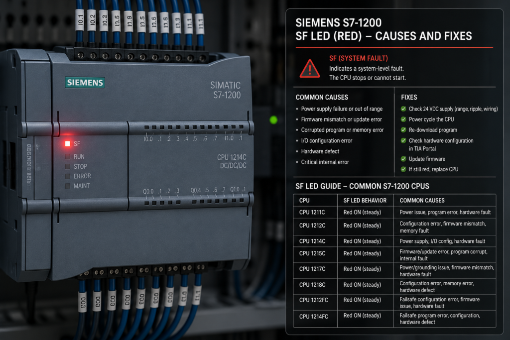
A red fault LED on a Siemens S7-1200 rarely tells you exactly what is broken.
It tells you where to begin looking.
The PLC may still bntered STOP mode. A signal module could be missing, a PROFINET device may have disappeared, the downloaded hardware configuration might not match the real station, or the CPU may have recorded a temporary event during a power interruption.
Then there is the more uncomfortable possibility: defective hardware.
Before replacing the CPU, deleting the project or reaching for the factory-reset option, slow down. The S7-1200 has a diagnostic buffer precisely for this situation, and in most cases it will tell you far more than the red light ever could.
Is It Really an “SF” LED?
On many Siemens PLCs, SF means System Fault.
Technicians commonly use the phrase “SF LED” for almost any red Siemens PLC fault indicator. However, current S7-1200 documentation names the red CPU indicator ERROR, not SF.
The standard S7-1200 CPU normally has these main status indicators:
- STOP/RUN
- ERROR
- MAINT
So when someone says, “The SF light is red on my S7-1200,” they usually mean the red ERROR LED.
The wording may differ between CPU generations, manuals and older equipment, but the troubleshooting principle is the same: identify the exact CPU order number, firmware version and LED pattern before drawing conclusions. First Check Whether the LED Is Flashing or Permanently On
Not every red indication means the same thing.
According to Siemens’ current S7-1200 documentation:
- A flashing red ERROR LED indicates an error such as an internal CPU error, memory-card problem or hardware-configuration mismatch.
- A red flash lasting approximately three seconds can indicate a temporary event that is no longer present, such as the real-time clock returning to its default value after power loss.
- A solid red ERROR LED indicates defective hardware.
- If the firmware detects a defective state, all CPU LEDs may flash. t difference matters.
A flashing LED usually sends you toward the diagnostics, configuration and field equipment. A permanently illuminated red LED—especially when the CPU cannot be reached online—raises greater concern about the CPU hardware itself.
Still, do not diagnose from the red LED alone. Look at the entire pattern.
Read All the CPU LEDs Together
The ERROR indicator makes more sense when viewed beside the STOP/RUN and MAINT LEDs.
RUN LED solid green
The CPU is in RUN mode.
If the ERROR LED is also flashing, the PLC may still be executing its program while reporting a diagnostic problem elsewhere in the station.
Possible examples include:
- a missing I/O device;
- a faulty signal module;
- a channel diagnostic;
- a communication interruption;
- an access error that the program or CPU can tolerate;
- a configuration inconsistency.
A running PLC is not automatically a healthy PLC.
STOP/RUN LED solid yellow
The CPU is in STOP mode.
The diagnostic buffer should show why it stopped or why startup was prevented. Do not repeatedly force it back into RUN without reading that information first.
STOP/RUN alternating green and yellow
This indicates the CPU is in STARTUP. hort STARTUP indication after power is applied is normal. Remaining in STARTUP or repeatedly cycling between states suggests that the startup sequence cannot finish successfully.
MAINT LED flashing
The MAINT indicator can appear during maintenance-related conditions. On an S7-1200, it also flashes when a memory card is inserted. in, combinations matter more than one lonely lamp.
Take a photo or write down the exact LED states before cycling the power. That five-second habit can save quite a bit of guessing later.
Do Not Start by Resetting the PLC
A factory reset is not a diagnostic method.
It can remove useful configuration or force you into a more complicated recovery process without addressing the original fault. Power cycling can also make an intermittent problem disappear temporarily, taking the evidence with it.
Before changing anything:
- Record the LED pattern.
- Note what happened immediately before the fault.
- Save the current diagnostic buffer.
- Check the status of all attached modules and network devices.
- Back up the PLC project and online data where possible.
The first diagnostic events often reveal the original problem. Later events may only show the consequences.
For example, a field power supply fails first. Several remote devices then disappear. The PLC records I/O access errors, communication faults and perhaps a mode transition. If you focus only on the final message, you may spend an afternoon blaming software for a failed 24V fuse.
Open the Diagnostic Buffer in TIA Portal
The most useful first step is usually:
TIA Portal → CPU → Online & Diagnostics → Diagnostics → Diagnostic buffer
Siemens describes the diagnostic buffer as a Diagnostic buffer**
Siemens describes the diagnostic buffer as a chronological log of diagnostic events from the CPU and its assigned modules. The latest event appears at the top, and each entry includes a timestamp, category and description. Theower interruption. citeturn720301search0turn720301search1
To reach the online diagnostics view, you can select the CPU in the project or locate it through Online access, connect using thee and open Online & Diagnostics. citeturn720301search6
Read more than the first line.
Look for:
- the first incoming error;
- the device or hardware identifier involved;
- whether the fault is still incoming or has gone outgoing;
- the exact time it began;
- a transition from RUN to STOP;
- startup prevention;
- repeated communication loss;
- configuration or firmware incompatibility;
- I/O access errors;
- power-cycle events.
The newest message is not always the root cause. It is simply the newest message.
Save the Diagnostic Buffer Before Making Changes
If the problem is intermittent, export or photograph the diagnostic entries before restarting equipment.
The buffer may contain the only record of:
- a remote I/O station disappearing briefly;
- a channel reporting wire break;
- a CPU entering STOP;
- an illegal peripheral access;
- a memory-card error;
- an unexpected power interruption;
- a configuration mismatch.
The diagnostic buffer is a log, not just a fault lamp in text form. It records operating-m events in the order they occurred. citeturn720301search22
A useful maintenance report should include:
- CPU model and order number;
- firmware version;
- TIA Portal version;
- LED pattern;
- diagnostic-buffer export;
- time of failure;
- machine operating state;
- recent hardware or software changes.
“PLC had red light” is not a particularly generous handover to the next technician.
Cause 1: Downloaded Hardware Configuration Does Not Match the Real Station
A common cause of a flashing red ERROR LED is a mismatch between the configured hardware and the devices physically installed.
Siemens specifically lists a configuration error involving mie of a flashing red ERROR condition. citeturn539792search0
This can happen after:
- replacing a signal module with a different variant;
- selecting the wrong CPU version in TIA Portal;
- changing a signal board;
- moving modules into different positions;
- downloading an old project;
- using the wrong order number;
- changing firmware without updating the project;
- removing a configured module;
- adding hardware without downloading the revised configuration.
Two modules can look almost identical while having different order numbers, channel counts or firmware support.
How to fix it
Go online and compare the configured device with the actual station.
Check:
- exact CPU order number;
- firmware version;
- signal-board type;
- signal-module order numbers;
- module positions;
- communication-module types;
- configured device versions.
Then decide which side is wrong.
If the installed hardware is correct, update the TIA Portal device configuration and download it.
If the project is correct, install the expected module or correct the physical arrangement.
Do not blindly download a modified hardware configuration to a production machine without checking how it affects addresses, outputs and startup behaviour.
Cause 2: A Signal Module or Signal Board Has Failed
The CPU’s red ERROR LED can act as a summary indication for a problem elsewhere in the station.
Inspect the LEDs on:
- digital input modules;
- digital output modules;
- analogue input modules;
- analogue output modules;
- communication modules;
- signal boards;
- technology modules.
A module-level red DIAG LED or channel-fault LED can narrow the search considerably.
TIA Portal can display the diagnostic status of an individual module through its Online & Diagnostics view. Siemens provides module-status information including wheor has a problem. citeturn720301search9turn720301search23
Possible module faults
Depending on the module and enabled diagnostics, faults may include:
- missing load voltage;
- sensor-supply short circuit;
- output short circuit;
- wire break;
- analogue overflow or underflow;
- incorrect measurement range;
- module overheating;
- missing module;
- internal electronics failure.
How to fix it
Read the module-specific diagnostic message rather than replacing the card immediately.
Check field power, terminal wiring and connected loads first. An output module showing a fault may be protecting itself from a shorted solenoid cable rather than failing internally.
If replacement is necessary:
- Isolate the required energy sources.
- Confirm the replacement order number and version.
- Follow Siemens’ module-replacement procedure.
- Restore power.
- Check online diagnostics.
- Confirm that the outgoing event clears the fault.
Replacing a module without repairing the short circuit connected to it is an expensive way to test spare parts.
Cause 3: A PROFINET Device Is Missing
An S7-1200 may report an error when a configured PROFINET device cannot be reached.
Common causes include:
- remote I/O power failure;
- disconnected Ethernet cable;
- damaged connector;
- failed network switch;
- duplicate IP address;
- incorrect PROFINET device name;
- device replaced without assigning its name;
- wrong IP configuration;
- device firmware or type mismatch;
- network topology change.
The CPU may continue running, depending on its configuration and program, but the affected I/O may no longer update normally.
How to fix it
Start with the physical layer:
- Is the remote device powered?
- Are its LINK LEDs active?
- Is the Ethernet connector seated?
- Does the switch port show a connection?
- Is the cable damaged?
- Is the 24V field supply present under load?
Then use TIA Portal’s Accessible devices or online network view.
Verify:
- device name;
- IP address;
- device type;
- configured station assignment;
- module arrangement;
- firmware compatibility.
A replacement PROFINET device often needs its configured device name assigned before the PLC recognises it correctly.
The new unit may have the correct IP address and still remain invisible to the project because PROFINET identification relies heavily on the assigned device name.
Cause 4: I/O Access Errors
The CPU may attempt to read or write an address associated with hardware that is unavailable, incorrectly configured or no longer present.
Possible reasons include:
- a remote station dropping offline;
- a module removed from the configuration;
- incorrect logical addresses;
- program code using an obsolete peripheral address;
- inconsistent hardware and software versions;
- a device failing during process-image update.
The diagnostic buffer is especially important here because program and communication access errors may not be obvious from the general device view. Siemens notes that the CPU diagnostic buffer is required for detailed informam communication and access errors. citeturn720301search21
How to fix it
Identify the exact hardware identifier or address in the diagnostic message.
Then check:
- which tag or instruction uses that address;
- whether the module exists online;
- whether its configured address changed;
- whether the device was removed from the machine;
- whether communication is intermittent;
- whether the program should handle temporary device failure.
Do not simply suppress the error without understanding the process consequence.
If an unavailable input controls a safety-critical or damaging action, the program needs a deliberate fallback state—not merely fewer red icons in TIA Portal.
Cause 5: A Memory Card Problem
The S7-1200 ERROR LED may flash because of an error involving the SIMATIC memory card. Siemens includes memory-card eamples for a flashing red ERROR LED. citeturn539792search0
Possible causes include:
- unsupported card;
- corrupted contents;
- interrupted firmware update;
- incompatible project or CPU data;
- damaged card;
- improperly prepared transfer card;
- card inserted during an unsuitable operation.
How to fix it
Read the diagnostic buffer before removing the card.
Then verify:
- that it is a genuine supported SIMATIC memory card;
- how the card was prepared;
- whether it contains a firmware update or transfer project;
- whether the files match the CPU type;
- whether the update completed successfully.
Never treat an S7 memory card like an ordinary USB drive or consumer SD card.
Follow the Siemens procedure for the intended card function. If the card is suspected to be damaged, use a known-good supported card and preserve the original for analysis rather than casually reformatting it.
Cause 6: CPU Firmware and Project-Version Incompatibility
A project configured for one CPU firmware version may not match the firmware actually installed.
This can happen when:
- an old CPU is replaced with a newer one;
- a CPU is downgraded or updated;
- a project is migrated between TIA Portal versions;
- the wrong device version is selected from the hardware catalogue;
- the replacement CPU cannot support the configured firmware level.
The symptoms may include download problems, startup prevention, configuration errors or a persistent ERROR indication.
How to fix it
Compare:
- CPU order number;
- installed firmware;
- configured firmware in TIA Portal;
- TIA Portal hardware catalogue support;
- compatibility of connected modules.
Use Siemens’ supported firmware-update procedure and confirm that the firmware package is intended for the exact CPU.
A firmware update is not something to try randomly because the red light looks serious.
Serious-looking lights deserve more evidence, not more adventurous clicking.
Cause 7: Unstable 24V DC Supply
A PLC cannot operate reliably on an unreliable control supply.
The voltage may look correct while the machine is idle, then collapse when contactors, valves or other loads switch on.
Possible power-related causes include:
- undersized power supply;
- overloaded 24V circuit;
- loose +24V terminal;
- loose 0V connection;
- high-resistance fuse holder;
- failing power supply;
- poor terminal jumper;
- short circuit on another branch;
- excessive voltage drop;
- electrical noise from inductive loads.
A temporary power interruption can also produce diagnostic events. Siemens gives an RTC reset after power loss as an that can trigger a brief red flash. citeturn539792search0
How to fix it
Measure voltage:
- at the power-supply output;
- at the CPU terminals;
- during machine startup;
- while large 24V loads energise;
- between the CPU’s 0V and the intended reference point.
A basic multimeter may miss a very short voltage dip. A recording meter or oscilloscope can reveal transient drops that occur when a load switches.
Also inspect:
- DC protection devices;
- terminal tightness;
- conductor sizing;
- branch loading;
- coil suppression;
- cabinet grounding;
- power-supply DC-OK contact.
Do not forget the 0V conductor. A poor return connection can create faults that look like several unrelated device failures.
Cause 8: Shorted or Overloaded Outputs
A shorted solenoid, damaged cable or incorrectly wired load can cause an output-channel fault.
Depending on the CPU or signal module, the output may shut down to protect itself and report diagnostics to the controller.
How to fix it
Do not repeatedly reset the output into a known short circuit.
Disconnect or isolate the field load according to safe working procedures, then check:
- load resistance;
- cable insulation;
- polarity;
- coil suppression;
- output current;
- inrush current;
- shared commons;
- external power supply;
- damaged connectors.
If the fault clears with the load disconnected, the PLC output may be doing exactly what it should.
The red LED is not accusing the module. Sometimes it is defending it.
Cause 9: Analogue Channel Diagnostics
Analogue modules can report faults that digital circuits do not encounter.
These may include:
- wire break;
- sensor-supply failure;
- overflow;
- underflow;
- incorrect range selection;
- open current loop;
- reversed signal wiring;
- missing loop power.
For some S7-1200 analogue modules, a wire break and overflow can produce the same raw input value, requiring the program or diagnostic interrupt information to distinguish betweh behaviour for the SM 1231 family. citeturn720301search14
How to fix it
Check:
- configured measurement type;
- voltage or current range;
- two-wire versus four-wire transmitter wiring;
- loop power;
- channel terminals;
- shield connection;
- transmitter output;
- raw PLC value;
- channel diagnostic settings.
An open 4–20mA loop is not repaired by scaling the raw value differently.
Start with the circuit.
Cause 10: A Program Error or CPU STOP Event
The CPU diagnostic buffer records user-program erhanges into STOP. citeturn720301search0turn720301search22
Possible program-related problems include:
- invalid data access;
- unavailable I/O access;
- communication instruction errors;
- startup logic problems;
- excessive cycle behaviour;
- inconsistent blocks after an incomplete download;
- missing error-handling logic.
The exact reaction depends on the event, CPU configuration and program structure.
How to fix it
Open the relevant diagnostic event and note:
- affected block;
- instruction or address;
- event timestamp;
- CPU operating mode;
- whether the error is recurring.
Use online monitoring and cross-references to find the code associated with the event.
Correct the cause rather than automatically forcing the CPU into RUN.
A PLC that enters STOP every time a machine reaches the same sequence step is trying rather hard to tell you something.
Cause 11: Hardware Damage
A permanently illuminated red ERROR LED can indicate defective CPU hardware. Siemens’ currens solid red with defective hardware. citeturn539792search0
Possible causes include:
- incorrect supply voltage;
- reversed DC polarity on unsupported terminals;
- surge damage;
- lightning or switching transients;
- conductive contamination;
- overheating;
- water ingress;
- damaged backplane connection;
- failed internal electronics.
How to confirm it
Before condemning the CPU:
- Verify the correct supply voltage and polarity.
- Disconnect nonessential modules using approved procedures.
- Inspect for obvious damage or contamination.
- Attempt an online connection.
- Record the complete LED pattern.
- Check whether all LEDs are flashing.
- Test with a known-good supply.
- Consult the CPU-specific Siemens manual.
If solid red remains and the CPU cannot be diagnosed or recovered through the documented procedure, replacement or Siemens service may be required.
Do not move a suspect CPU directly into another machine without considering whether the original installation caused the damage.
Otherwise, you may obtain two defective CPUs and one still-unidentified fault.
A Practical Troubleshooting Sequence
When the S7-1200 red ERROR or “SF” LED appears, use this order.
Step 1: Put the machine in a safe condition
Do not focus on restoring production before considering hazardous motion, pressure, heat and stored energy.
Step 2: Record all LEDs
Note whether each LED is:
- off;
- solid;
- flashing;
- alternating.
Check the CPU and every attached module.
Step 3: Check whether the CPU is in RUN or STOP
This immediately tells you whether the controller is still executing its program.
Step 4: Go online without downloading
Open Online & Diagnostics and read the actual PLC before changing the project.
Step 5: Save the diagnostic buffer
Preserve the evidence.
Step 6: Find the first relevant incoming event
Work from the original fault forward, not merely from the newest consequence backward.
Step 7: Open the device view
Look for the module or network device marked with a diagnostic symbol.
Step 8: Compare configured and actual hardware
Check order numbers, firmware, slot positions and device names.
Step 9: Check 24V power and communication
Measure under real operating conditions, not just while the machine is idle.
Step 10: Correct one fault at a time
After each repair, confirm that the diagnostic event changes from incoming to outgoing and that no related fault remains.
Step 11: Reset only when the cause is understood
A cleared light is not proof of a completed repair.
What Not to Do
Avoid these familiar shortcuts:
- Do not factory-reset the CPU first.
- Do not download an old project without checking the installed hardware.
- Do not replace the CPU before reading the diagnostics.
- Do not bypass faulty I/O just to clear the red LED.
- Do not increase the power-supply voltage blindly.
- Do not repeatedly energise a shorted output.
- Do not assume RUN mode means all I/O is valid.
- Do not erase the diagnostic buffer before saving it.
- Do not ignore intermittent red indications after power disturbances.
A fault that clears after a restart may still return during production.
Intermittent faults are not imaginary. They are simply better at hiding.
Can the S7-1200 Web Server Show Diagnostics?
The S7-1200 includes a web server that can provide CPU and process information when it has been enabled and configured in TIA Portal. Its standard pages can include diato the configured access privileges. citeturn720301search7
A permitted user can access the web pages throu device on the appropriate network. citeturn720301search18
This can be useful when TIA Portal is unavailable at the machine.
However, web-server access must be configured securely. Do not expose the PLC carelessly to untrusted networks merely because remote diagnostics would be convenient.
Convenience has started enough cybersecurity incidents already.
The Red LED Is a Starting Point, Not a Diagnosis
The red ERROR—or informally, SF—LED on a Siemens S7-1200 can indicate many different problems.
Common causes include:
- mismatched hardware configuration;
- missing signal modules;
- PROFINET device failure;
- I/O access errors;
- memory-card problems;
- firmware incompatibility;
- unstable 24V supply;
- output short circuits;
- analogue channel faults;
- program errors;
- defective CPU hardware.
The quickest reliable answer normally comes from the diagnostic buffer.
Read the complete LED pattern, go online, save the events and identify the first incoming fault before changing anything. A flashing red LED often points to a diagnosable system problem. A solid red LED deserves more concern because it can indicate defective hardware.
Either way, the light itself is not the repair instruction.
It is the PLC saying, rather plainly: check my diagnostics before you start guessing.