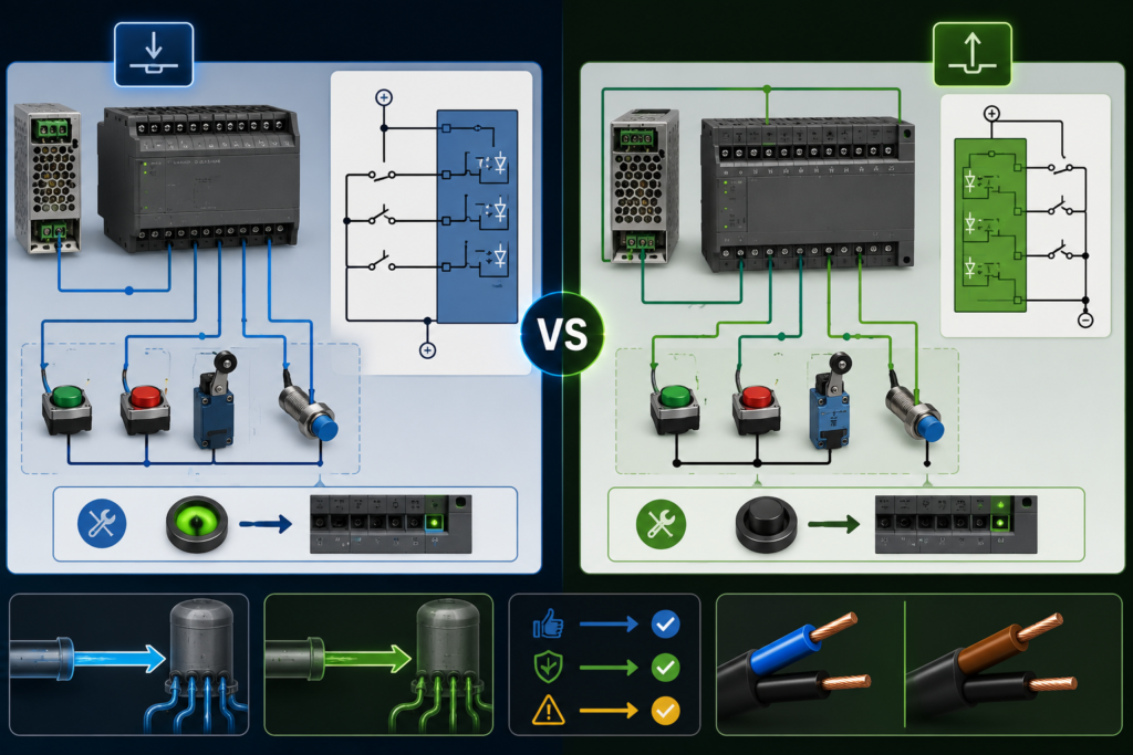
Few industrial wiring terms create as much unnecessary confusion as sinking and sourcing.
You connect a perfectly good 24V sensor to a PLC input. The sensor’s indicator turns on, the target is clearly detected, yet the PLC input remains stubbornly dark.
The sensor works.
The PLC works.
The wiring looks reasonable.
Still, nothing happens.
Very often, the problem is that the sensor and PLC input are both trying to source current—or both are waiting to sink it. Electrically, they are incompatible even though both devices are labelled 24V DC.
The easiest way to understand sinking and sourcing is to stop thinking about the signal as “sending voltage” and start thinking about where conventional current comes from and where it goes.
A sourcing device supplies current from the positive side of the power supply.
A sinking device provides a path for current toward 0V.
For current to flow, one side must source and the other must sink.
That is the whole idea.
Unfortunately, automation terminology then wraps that simple idea in PNP sensors, NPN sensors, common terminals, input-module diagrams and regional wiring habits. So let’s unwrap it carefully.
Start With a Complete Current Path
A PLC input does not turn on merely because a wire contains 24 volts.
Current must flow through the input circuit.
For a basic DC input to become active, the electrical path must be complete:
[
+24V \rightarrow Switching\ Device \rightarrow PLC\ Input \rightarrow 0V
]
The exact order depends on whether the field device or the PLC input provides the positive side.
One device supplies current.
The other receives that current and provides a route back to 0V.
No complete path, no current.
No current, no active input.
This is why measuring 24V on one wire does not always prove that the input is wired correctly. Voltage can exist without meaningful current flowing through the PLC’s internal input circuit.
What Does “Sourcing” Mean?
A sourcing device supplies conventional current from the positive side of the DC power supply.
When it turns on, its output connects the load or PLC input toward +24V.
Current flows out of the device.
That is why it is described as sourcing current.
A typical three-wire PNP sensor behaves as a sourcing device:
- brown wire connects to +24V;
- blue wire connects to 0V;
- black output wire supplies positive voltage when the sensor is active.
When the sensor detects a target, current flows from +24V through the sensor’s output transistor, out through the black wire and into the PLC input.
The PLC input must then provide the return path to 0V.
Therefore, a sourcing sensor requires a sinking PLC input.
What Does “Sinking” Mean?
A sinking device provides a path from the load or input signal toward 0V.
When it turns on, its output connects the signal wire to the negative side of the supply.
Current flows into the device and then toward 0V.
That is why it is described as sinking current.
A typical three-wire NPN sensor behaves as a sinking device:
- brown wire connects to +24V;
- blue wire connects to 0V;
- black output wire is switched toward 0V when active.
In this arrangement, the PLC input must provide current from the positive side.
Therefore, a sinking NPN sensor requires a sourcing PLC input.
The two devices complete one current path together.
The Pairing Rule
The simplest rule to remember is:
- Sourcing field device → sinking PLC input
- Sinking field device → sourcing PLC input
Or, in sensor terminology:
- PNP sensor → sinking input
- NPN sensor → sourcing input
Opposites pair together.
A source needs a sink.
Connecting a sourcing sensor to a sourcing input usually does not create a complete path. Connecting a sinking sensor to a sinking input has the same problem.
It is like placing two water pumps face-to-face with no drain, or two drains together with no water supply. The parts may be perfectly functional, but the arrangement achieves very little.
Why the Terminology Feels Backwards
Suppose a PNP sensor sends +24V to a PLC input.
You might naturally call that a sourcing input because the input receives a positive signal.
In common industrial terminology, however, the PLC input is often called sinking because it provides the path through its internal circuitry to 0V.
The name describes what the input module does to current, not the type of signal arriving at its terminal.
Likewise, an input that works with an NPN sensor may be called sourcing because the input module supplies current toward the field device.
This creates phrases that initially sound contradictory:
- a sourcing sensor connects to a sinking input;
- a sinking sensor connects to a sourcing input.
Once you follow the current path, the language becomes less mysterious.
Not elegant, perhaps. But less mysterious.
PNP Sensors Are Sourcing Devices
PNP sensors are extremely common in European industrial automation.
When a PNP output turns on, it connects the sensor’s output toward the positive supply.
A simplified current path is:
[
+24V \rightarrow PNP\ Sensor\ Output \rightarrow PLC\ Input \rightarrow Input\ Common\ at\ 0V
]
The PLC input module’s common terminal is connected to 0V.
When the sensor activates, its black output wire rises toward +24V. Current flows through the PLC’s internal input circuitry and returns through the common terminal to 0V.
The input LED illuminates, and the PLC program sees a logic 1.
Typical PNP sensor wiring
For a standard three-wire sensor:
- Brown: +24V
- Blue: 0V
- Black: signal to PLC input
- PLC input common: 0V
When inactive, the output is normally off.
When active, the black wire supplies positive voltage.
This is often called positive switching.
NPN Sensors Are Sinking Devices
NPN sensors switch their output toward 0V.
A simplified current path is:
[
+24V \rightarrow PLC\ Input\ Common \rightarrow PLC\ Input \rightarrow NPN\ Sensor\ Output \rightarrow 0V
]
Here, the PLC input common is connected to +24V.
The input module provides current through its internal circuitry. When the NPN sensor activates, it connects the signal wire to 0V and completes the circuit.
The PLC input then turns on.
Typical NPN sensor wiring
For a standard three-wire sensor:
- Brown: +24V
- Blue: 0V
- Black: signal to PLC input
- PLC input common: +24V
When inactive, the output does not provide the path to 0V.
When active, the black wire is pulled toward 0V.
This is often called negative switching.
A Simple Visual Comparison
PNP sensor with sinking PLC input
+24V
  |
  | Brown
[PNP Sensor]
  |
  | Black output
  |
[PLC Input]
  |
[PLC Common]
  |
  0V
The sensor supplies positive current to the PLC input.
NPN sensor with sourcing PLC input
+24V
  |
[PLC Common]
  |
[PLC Input]
  |
  | Black output
[NPN Sensor]
  |
  | Blue
  |
  0V
The PLC input supplies current, and the sensor switches it to 0V.
The same basic input function is achieved using opposite current directions.
What Is Inside a PLC Digital Input?
A 24V PLC input is not simply a wire connected directly to the processor.
Its internal circuit may contain:
- current-limiting resistors;
- optocouplers;
- filtering capacitors;
- protection diodes;
- voltage thresholds;
- surge protection;
- status LEDs;
- diagnostic electronics.
When enough current flows through this input circuit, the module reports an ON state to the PLC processor.
The processor itself may operate at only 3.3V or another low internal voltage. The input circuitry isolates and converts the industrial 24V signal into a safe internal logic level.
That is why input polarity matters.
The current must flow through the internal LED, optocoupler or detection circuit in the correct direction. Reversing the common connection may prevent the input from working and could damage a module that lacks sufficient protection.
What Does the PLC Common Terminal Do?
Digital input modules normally divide their input channels into groups.
Each group has a common terminal labelled with something such as:
- M;
- 0V;
- COM;
- C;
- L+;
- 1M;
- 2M;
- S/S;
- input common.
The exact label depends on the manufacturer.
This terminal establishes the reference and return path for that group of inputs.
For a sinking input group used with PNP sensors, the common is typically connected to 0V.
For a sourcing input group used with NPN sensors, the common is typically connected to +24V.
Some PLC input groups have fixed polarity. Others are configurable by connecting the common terminal to either +24V or 0V.
Never assume.
Check the module’s wiring diagram.
The letters stamped beside the terminal block are cheaper to read than the smoke released after guessing incorrectly.
Fixed-Polarity and Configurable Inputs
Not all PLC input modules behave the same way.
Fixed sinking inputs
These inputs are designed for sourcing devices, normally PNP sensors.
Their common or reference terminal is connected to 0V according to the manufacturer’s diagram.
Fixed sourcing inputs
These inputs are designed for sinking devices, normally NPN sensors.
Their common is connected to +24V.
Configurable sinking or sourcing inputs
Some PLCs allow an input group to be configured for either style by changing the common connection.
For example, an S/S terminal might be connected:
- to 0V for PNP sensors;
- to +24V for NPN sensors.
However, every input in that common group usually has to use the same logic type.
You cannot normally configure one channel in the group for PNP and the next for NPN unless the module provides separate commons or individually configurable channels.
How to Identify a Sinking PLC Input
A wiring diagram for a sinking input commonly shows:
- the input common connected to 0V;
- the field switch or sensor connecting +24V to the input terminal;
- current flowing into the input from the positive side.
A simple mechanical switch would be wired like this:
+24V → Push Button → PLC Input → PLC Common → 0VClose the push button and current flows into the input.
The external device sources the current.
The PLC input sinks it.
How to Identify a Sourcing PLC Input
A sourcing input diagram commonly shows:
- the input common connected to +24V;
- the PLC input providing current toward the field device;
- the external switch or sensor completing the path to 0V.
A mechanical switch would be wired like this:
+24V → PLC Common → PLC Input → Push Button → 0VClose the push button and current flows from the PLC input through the switch to 0V.
The PLC input sources current.
The field device sinks it.
Mechanical Contacts Can Work With Either Type
A basic dry contact, such as a push button or relay contact, does not have PNP or NPN electronics.
It simply opens or closes.
Because it is electrically passive, it can usually be wired for either sourcing or sinking input logic.
For a sinking PLC input:
+24V → Contact → InputFor a sourcing PLC input:
Input → Contact → 0VThe contact itself does not care which direction conventional current flows, provided its voltage and current ratings are respected.
Electronic sensors are different because their output transistors have a defined polarity and current direction.
Why Europe Commonly Uses PNP Sensors
PNP sensors and sinking PLC inputs are especially common in European automation systems.
One frequently mentioned advantage involves faults to grounded machine metal.
In many 24V control systems, 0V is bonded to protective earth at one controlled point.
With a PNP signal arrangement, an accidental short from the signal wire to grounded metal tends to pull the signal toward 0V. This usually produces an OFF state or short-circuit fault rather than a false ON command.
With an NPN arrangement, the PLC input is supplied from +24V and the sensor normally switches toward 0V. Depending on the exact wiring, a signal wire shorted to grounded metal could imitate an active NPN sensor and create an unintended ON signal.
This does not mean PNP systems are automatically fail-safe.
Fault behaviour depends on:
- grounding method;
- input design;
- cable routing;
- diagnostics;
- whether the function is active-high or active-low;
- the machine’s safety architecture.
Still, the behaviour during a short to grounded metal is one reason PNP wiring is widely preferred in many industrial installations.
Why NPN Sensors Are Still Common
NPN sensors remain widely used, particularly in equipment and markets where negative-switching control traditions are established.
They may also appear in:
- imported machinery;
- older control systems;
- Japanese and other Asian equipment;
- custom electronic systems;
- applications designed around sinking transistor outputs.
NPN is not inherently wrong or inferior.
A properly designed NPN system can operate reliably for years.
The main requirement is consistency. The PLC input, sensor output, commons and grounding arrangement must all be compatible.
Problems begin when someone replaces a failed sensor with “the same size one” without checking whether the old device was PNP or NPN.
It fits the bracket beautifully.
Electrically, it may as well be a doorstop.
Sourcing and Sinking Outputs Use the Same Principle
The terminology also applies to PLC outputs.
A sourcing output supplies positive current to a load. This is commonly a PNP transistor output.
A sinking output switches the load toward 0V. This is commonly an NPN transistor output.
PNP sourcing output
PLC Output → Load → 0VWhen active, the output supplies +24V to the load.
NPN sinking output
+24V → Load → PLC OutputWhen active, the output provides the path to 0V.
This is the same current-direction principle used for inputs.
However, be careful not to mix the two conversations.
A sinking PLC input accepts current from a sourcing sensor.
A sinking PLC output carries current from a load toward 0V.
The word sinking describes the module’s role in that particular circuit.
PNP Does Not Always Mean Normally Open
PNP and NPN describe the transistor output type.
They do not describe whether the sensor is normally open or normally closed.
A sensor can be:
- PNP normally open;
- PNP normally closed;
- NPN normally open;
- NPN normally closed;
- complementary, with both output functions.
For a normally open sensor, the output transistor turns on when the target is detected.
For a normally closed sensor, the output is active in the normal undetected state and turns off when the target is detected.
Therefore, reading “PNP” on the label is not enough to understand the complete behaviour.
You also need to check:
- normally open or normally closed;
- number of wires;
- supply range;
- output current;
- connector pinout;
- diagnostic behaviour.
Why a Sensor LED Can Turn On While the PLC Input Stays Off
The sensor’s indicator LED normally shows that the sensor has detected a target or changed its output state.
It does not prove that current is flowing through the PLC input.
Possible reasons include:
- PNP sensor connected to a sourcing input;
- NPN sensor connected to a sinking input;
- missing PLC input common;
- broken signal conductor;
- separate 0V references not connected;
- insufficient input voltage;
- incorrect connector pinout;
- damaged input channel;
- sensor output overloaded;
- two-wire sensor leakage or voltage-drop issue.
The sensor can power its internal electronics and illuminate its LED while the output circuit remains incompatible with the PLC.
Always check the complete current path.
Common Wiring Mistake: Missing 0V Connection
Suppose a sensor is powered by one 24V supply and the PLC input module by another.
The positive voltages may both measure correctly, yet the input may not operate because the two circuits do not share the required reference or isolated interface.
For a non-isolated PNP signal, the sensor’s 0V and PLC input common normally need an appropriate common reference.
Without it, current may have no return path.
This often happens when:
- remote sensors use another power supply;
- separate cabinet sections were installed;
- a 0V fuse has opened;
- a terminal jumper is missing;
- a connector carries +24V and signal but no reference.
Do not connect separate supplies together blindly, especially if they are intentionally isolated.
Review the grounding and control-power design first.
Common Wiring Mistake: Reversing Brown and Blue
For many IEC-style three-wire DC sensors:
- brown is +24V;
- blue is 0V;
- black is output.
This colour convention is extremely common.
It is not a substitute for the datasheet.
Special sensors, old equipment and custom cable assemblies may use different colours. Four-wire sensors may include a white wire for a second or complementary output.
Reverse polarity protection may save the sensor from incorrect wiring.
Or it may not.
A one-minute pinout check is generally quicker than finding another sensor in the spare-parts store.
Common Wiring Mistake: Confusing the Input Common With 0V
Technicians sometimes assume every terminal marked COM must connect to 0V.
That is true for many sinking input modules.
It is false for sourcing inputs, where the common may need +24V.
On configurable modules, connecting the common to the wrong side changes which sensor type the group can accept.
If every input in one group remains off, inspect the common terminal before checking eight separate field devices.
One missing jumper can make an entire input card appear dead.
Common Wiring Mistake: Mixing PNP and NPN in One Group
A PLC input group may share one common terminal across four, eight or sixteen channels.
If that common is connected to 0V, the group is arranged for sourcing field devices such as PNP sensors.
An NPN sensor added to the same group may not work because it requires the opposite current arrangement.
Possible solutions include:
- using another input group with a separate common;
- selecting a compatible sensor;
- using an interposing relay;
- installing a signal converter;
- changing the complete group configuration where permitted.
Do not reverse the common for one new sensor without checking every existing channel in that group.
You may repair one input and disable fifteen others. Efficient, in a strange way.
Common Wiring Mistake: Testing Only With a Multimeter
A high-impedance multimeter draws very little current.
It may display nearly 24V on a signal wire due to:
- leakage current;
- capacitive coupling;
- internal electronics;
- an open circuit;
- residual voltage.
The PLC input may still remain off because the available current is too low.
Testing under load or measuring current can provide more useful information, provided it is performed safely and correctly.
A test lamp or resistor may sometimes help distinguish a real output from a ghost voltage, but it must be suitable for the circuit and must not overload the sensor.
Do not use a random automotive bulb on a delicate sensor output merely because both systems happen to mention 24 volts.
Two-Wire Sensors Can Create Additional Confusion
Two-wire electronic sensors are connected in series with the PLC input or load.
Because they need power for their internal electronics, they typically exhibit:
- off-state leakage current;
- an on-state voltage drop;
- minimum load-current requirements.
A two-wire sensor may allow enough leakage current to make a sensitive PLC input flicker or remain weakly active.
Alternatively, its on-state voltage drop may leave too little voltage for the PLC input to reach its ON threshold.
Possible solutions include:
- a load resistor;
- a compatible input module;
- an interface relay;
- a three-wire sensor;
- a manufacturer-recommended suppressor or converter.
The exact solution depends on the sensor and input specifications.
Sinking and sourcing still matter, but two-wire devices add another layer to the puzzle.
How to Check Whether a Sensor Is PNP or NPN
Start with the label or datasheet.
Look for markings such as:
- PNP;
- NPN;
- sourcing;
- sinking;
- positive switching;
- negative switching;
- output circuit diagram.
If documentation is unavailable, voltage measurements may provide clues.
For a powered three-wire sensor:
Suspected PNP output
Measure between the black output wire and 0V.
When active, the output should rise toward +24V.
Suspected NPN output
Measure between +24V and the black output wire.
When active, the output should be pulled toward 0V, so nearly the full supply voltage appears across that measurement.
Testing should be done with appropriate care. The output may require a load, and a multimeter alone may not reveal leakage or current capability.
The wiring diagram remains the safer and more reliable answer.
How to Check Whether a PLC Input Is Sinking or Sourcing
Use the PLC hardware manual or module wiring diagram.
Look for the current path and common-terminal connection.
If the diagram shows the field device applying +24V to the input while the input common connects to 0V, it is a sinking input.
If the diagram shows the input common connected to +24V and the field device switching the input toward 0V, it is a sourcing input.
You can also check the module description for terms such as:
- Type 1, Type 2 or Type 3 input;
- source input;
- sink input;
- PNP compatible;
- NPN compatible;
- positive logic;
- negative logic.
Terminology is not perfectly consistent between manufacturers.
Follow the actual circuit diagram when the wording feels ambiguous.
Current arrows are less poetic, but more dependable.
A Practical PNP Troubleshooting Example
A PNP proximity sensor detects a metal target. Its LED turns on, but PLC input I0.3 remains off.
Check the circuit in this order:
- Confirm brown has +24V relative to blue.
- Confirm blue is connected to the correct 0V.
- Measure black relative to blue while the sensor is active.
- Confirm black rises toward +24V.
- Check continuity from black to PLC input
I0.3. - Confirm the PLC input common is connected to 0V.
- Confirm the input group supports PNP or sourcing field devices.
- Measure voltage directly at the PLC terminal.
- Check whether the input LED activates.
- Test another known-good input if permitted.
If +24V reaches the input terminal and the common is correct but the channel remains off, the channel may be damaged or its threshold may not be reached.
If voltage exists at the sensor but not at the PLC, the cable or terminal path is the likely problem.
A Practical NPN Troubleshooting Example
An NPN photoelectric sensor detects a box, but the PLC input remains off.
Check:
- Brown to +24V.
- Blue to 0V.
- Black output wiring to the PLC input.
- PLC input common connected to +24V.
- Input module compatibility with NPN sensors.
- Black output pulled toward 0V when active.
- Shared reference between sensor and input circuit.
- Input current and voltage thresholds.
If the input common is connected to 0V, the circuit is probably arranged for PNP sensors. The NPN sensor cannot complete the required path because both the sensor and PLC input are effectively waiting near the negative side.
Can an Interposing Relay Convert PNP to NPN?
A relay can provide an interface between incompatible signal types.
For example, a PNP sensor can energise a 24V relay coil. The relay’s isolated contact can then be wired to suit a sourcing PLC input.
This provides:
- polarity conversion;
- galvanic separation;
- multiple contacts;
- simple troubleshooting.
However, relays introduce:
- switching delay;
- mechanical wear;
- coil current;
- contact bounce;
- additional cabinet space;
- another component that can fail.
For frequent or high-speed signals, an electronic signal converter or optocoupler interface may be more suitable.
A relay is useful.
It is not seasoning to be added to every circuit.
What About Push-Pull Outputs?
Some devices use push-pull outputs.
A push-pull output can actively drive the signal both toward +24V and toward 0V, rather than switching in only one direction.
This can provide:
- faster signal transitions;
- stronger noise immunity;
- compatibility with certain controller inputs;
- reduced reliance on pull-up or pull-down circuitry.
Push-pull outputs are common in encoders, high-speed sensors and some electronic devices.
Compatibility still needs to be checked.
A push-pull output should not be connected casually to an input or another output that drives the line in opposition. Two active outputs fighting each other can create excessive current and damage.
The phrase “works with both” should always be read together with the wiring diagram.
What Are Complementary Outputs?
A complementary sensor may provide two output wires:
- one normally open;
- one normally closed.
For example:
- black wire activates when the target is detected;
- white wire provides the opposite state.
Both outputs may still be PNP or both may be NPN.
Complementary does not mean one PNP and one NPN.
It means the logical states oppose each other.
This can be useful when the controller needs both signal conditions or when one output is used for diagnostics.
Active-High and Active-Low Logic
Sourcing and sinking are electrical concepts.
Active-high and active-low describe logical interpretation.
An active-high input is considered true when its signal is at a higher voltage.
An active-low input is considered true when its signal is pulled low.
PNP systems are often associated with active-high logic because the sensor applies +24V when active.
NPN systems are often associated with active-low behaviour because the sensor pulls the signal toward 0V.
However, PLC programming can invert the logical interpretation.
A normally closed PNP sensor might provide +24V in its healthy state and remove it during detection or fault. The PLC program can interpret either state according to the process requirement.
Do not assume the electrical ON state automatically means the machine condition is true.
The program decides what the signal means.
Are Sinking Inputs Safer?
Neither input type is universally safer.
Safety depends on how the system responds to predictable faults.
Questions to ask include:
- What happens if the signal wire breaks?
- What happens if it shorts to 0V?
- What happens if it shorts to +24V?
- What happens if the sensor loses power?
- Can a single fault produce an unintended command?
- Is the signal part of a safety-related function?
For ordinary automation, PNP sensors with sinking inputs are common and convenient.
For safety functions, use properly designed and certified safety devices, monitored circuits and the required architecture.
A PNP sensor connected to a PLC does not become safety-rated merely because its fault behaviour seems sensible.
Safety requires rather more paperwork—and engineering—than that.
Quick Reference Table
| Field device | Device action when ON | Required PLC input | Typical input common |
|---|---|---|---|
| PNP sensor | Supplies +24V current | Sinking input | 0V |
| NPN sensor | Switches current to 0V | Sourcing input | +24V |
| Mechanical contact with +24V | Supplies positive signal | Sinking input | 0V |
| Mechanical contact to 0V | Provides negative return | Sourcing input | +24V |
The two sides must complement each other.
Source to sink.
Sink to source.
The Simplest Way to Remember It
Imagine conventional current leaving the positive terminal of a 24V power supply and travelling toward 0V.
A sourcing device pushes that current out from the positive side.
A sinking device receives it and gives it a path to the negative side.
For a PLC input circuit:
- a PNP sensor sources current;
- the PLC input sinks it.
For an NPN circuit:
- the PLC input sources current;
- the NPN sensor sinks it.
Once you identify who provides +24V and who completes the path to 0V, the terminology becomes much easier.
Do not begin with the labels.
Begin with the current path.
Final Answer
Sinking and sourcing describe the direction of current flow between a field device and a PLC input.
A sourcing device supplies current from +24V. A sinking device provides the path to 0V.
That means:
- PNP sensors are normally sourcing devices.
- NPN sensors are normally sinking devices.
- PNP sensors connect to sinking PLC inputs.
- NPN sensors connect to sourcing PLC inputs.
The PLC input common determines which arrangement the input group uses. A common connected to 0V usually supports PNP sensors. A common connected to +24V usually supports NPN sensors.
Whenever an input refuses to work, trace the complete path:
[
+24V \rightarrow Source \rightarrow Input\ Circuit \rightarrow Sink \rightarrow 0V
]
If that path is complete, current flows and the input turns on.
If it is not, both devices can sit there with perfectly healthy LEDs while the PLC continues pretending nothing happened.