Some of the more puzzling control-circuit faults arise from grounds, commons, and sneak paths — unwanted connections that let current take routes the schematic never intended — and understanding these clarifies faults that otherwise seem to defy logic. When a circuit does something the schematic says is impossible, an extra, unintended connection is often the cause. This chapter covers grounds, commons, and sneak paths and how to recognize and find them.
The common and the sneak path
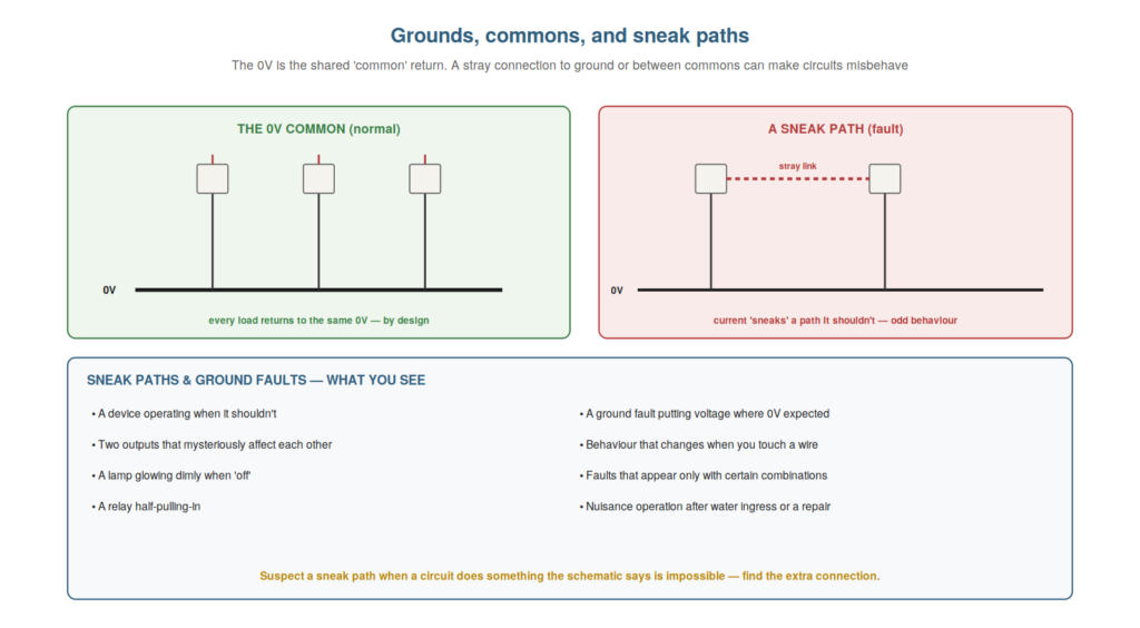
To understand sneak paths, you first understand the common — the shared 0V return — and how an unwanted connection turns into a sneak path. In a control circuit, the 0V is a shared common: every load returns to the same 0V rail, which is normal and by design (all the rungs share the common return). A sneak path arises when an unwanted extra connection appears — a stray link between two points that should not be connected, or a fault bridging points — letting current flow by a route the schematic never intended. Because the circuit shares the common and now has this extra connection, current can ‘sneak’ through the unintended path, producing behavior the schematic does not predict. So the common is the normal shared return, and a sneak path is an abnormal extra connection that creates unintended current routes. Understanding this distinction — the intended common versus the unintended sneak path — is the basis for recognizing sneak-path faults, which appear as behavior the schematic says is impossible because current is taking a path the schematic does not show. Understanding the common and the sneak path — the 0V common as the normal shared return and a sneak path as an unwanted extra connection creating unintended current routes — is the basis for recognizing this class of fault, so that you distinguish the intended sharing of the common return from the abnormal extra connection that lets current sneak a route the schematic never intended, which is what produces the puzzling behavior of sneak-path faults: the circuit does something the drawing says is impossible precisely because current is flowing through a path the drawing does not show, the extra connection you must find.
Recognizing sneak-path symptoms
Sneak paths produce characteristic symptoms, and understanding how to recognize them lets you identify this kind of fault when you meet it. The symptoms of a sneak path or ground fault are typically things the schematic says should not happen: a device operating when it should not (current reaching it by an unintended route), two outputs mysteriously affecting each other (linked by a stray connection), a lamp glowing dimly when it should be off (a small current sneaking through), a relay half-pulling-in (partial current via a sneak path), voltage appearing where 0V is expected (a ground fault), or behavior that changes when you touch or move a wire (a marginal stray connection). The common thread is behavior the schematic cannot explain — because the current is taking a path the schematic does not show. So recognizing these symptoms — impossible-seeming behavior, devices interacting, dim or partial operation — identifies a likely sneak-path fault. Understanding how to recognize sneak-path symptoms — the characteristic impossible-seeming behavior — lets you identify this kind of fault. It reinforces that sneak paths show as behavior the schematic cannot explain (devices operating wrongly, interacting, or partially operating), signaling an unintended connection. Understanding how to recognize sneak-path symptoms — devices operating when they should not, outputs affecting each other, dim or partial operation, voltage where 0V is expected, or behavior changing when a wire is touched — lets you identify this kind of fault when you meet it, so that when a circuit does something the schematic says is impossible, you recognize the signature of a sneak path or ground fault (current taking an unintended route via an extra connection) and know to look for the unwanted connection, which is the key to identifying a class of fault that otherwise seems to defy the logic of the drawing.
Finding the unwanted connection
Finding a sneak path means finding the unwanted connection, and understanding the approach lets you locate this often-elusive fault. Since the fault is an extra connection the schematic does not show, you find it by comparing the actual circuit to the schematic and looking for where reality has an extra path. Practically: identify the points that are behaving as if connected (the two outputs affecting each other, the device operating wrongly) and look for the unintended connection between them — a stray wire, a fault bridging terminals, water or debris across contacts, a miswire, or a ground fault to the frame. Testing can help: with the circuit isolated, continuity between points that should not be connected reveals the sneak path (they show continuity when they should not). Common physical causes — water ingress, chafed insulation, metal debris, a miswire after a repair — guide where to look. So finding the unwanted connection means locating where the actual circuit has a path the schematic does not, using the symptom to know which points are involved and testing or inspecting for the stray connection. Understanding this approach — finding where reality has an extra connection the schematic lacks — lets you locate the sneak path. It reinforces that sneak paths are found by comparing circuit to schematic and locating the unintended connection between the involved points. Understanding how to find the unwanted connection — comparing the actual circuit to the schematic and locating the extra path reality has, using the symptom to identify the involved points and testing continuity or inspecting for the stray connection between them — lets you locate this often-elusive fault, so that you hunt the sneak path by finding where the real circuit has a connection the drawing does not show (a stray wire, bridged terminals, water, debris, a miswire, or a ground fault), guided by the symptom to the points involved and by the common physical causes to where to look, which resolves the puzzling sneak-path fault by finding and removing the unintended connection at its root.
The floating vs. grounded 0V
A detail that affects ground faults is whether the 0V is grounded or floating, because it changes how a ground fault behaves and is detected. In some systems the 0V rail is connected to earth ground (a grounded system); in others it is deliberately isolated from earth (a floating system). This matters for ground faults: in a grounded-0V system, a fault connecting +24V to earth is effectively a short to 0V (since 0V is earth), which draws current and may blow a fuse; in a floating system, a single fault from +24V to earth may not cause an immediate problem (no return path through earth), but it compromises the isolation, so a second earth fault would then cause trouble. Understanding which system you have explains how a ground fault behaves: an immediate fault-like symptom in a grounded system, or a hidden first-fault in a floating one. So understanding the floating versus grounded 0V explains the differing behavior and detection of ground faults. Understanding whether the 0V is floating or grounded — connected to earth or deliberately isolated — changes how a ground fault behaves and is detected, so that you understand a +24V-to-earth fault acts like a short in a grounded-0V system (drawing current, perhaps blowing a fuse) but may be a hidden first-fault in a floating system (compromising isolation until a second fault causes trouble), which explains the differing symptoms of ground faults between system types and helps you interpret and detect them according to whether your system’s 0V is grounded or floating.
Scenario: the two lamps that shared a fault
A scenario shows recognizing and finding a sneak path. Two indicator lamps behaved strangely: switching on one made the other glow dimly, which the schematic said was impossible — they were separate circuits. The technician recognized this as a sneak-path symptom: two outputs affecting each other meant an unwanted connection between them. He identified the two points that seemed linked (the two lamp circuits) and looked for the unintended connection. Isolating the circuit, he tested continuity between the two points that should not be connected — and found continuity where there should be none. Tracing it, he found the cause: water ingress in a junction box had bridged two terminals, creating a sneak path that let current from one lamp circuit reach the other. Drying and cleaning the box, and sealing it, removed the sneak path, and the lamps behaved independently again. Recognizing the impossible-seeming symptom and finding the unwanted connection had solved it. This scenario shows recognizing a sneak-path symptom and finding the unwanted connection. Understanding sneak paths let the technician recognize the interacting lamps as an unwanted connection and find the water-bridged terminals. It reinforces that sneak paths show as impossible-seeming interaction and are found by locating the unintended connection. The scenario reinforces sneak-path diagnosis: the technician solved two lamps mysteriously interacting by recognizing the impossible-seeming symptom as a sneak path and finding the unwanted connection — water bridging two terminals — illustrating how recognizing behavior the schematic says is impossible as a sneak path, and then hunting the unintended connection between the involved points, resolves these puzzling faults at their root.
Diode-caused sneak paths and back-feeds
A more advanced sneak-path cause worth understanding is the back-feed, sometimes involving diodes or shared connections, because it explains sneak paths that are about circuit topology rather than a stray wire. A back-feed occurs when current reaches a point by an unintended reverse route through the circuit — for example, through a device or a shared connection that was not meant to feed that point, or (where diodes are involved) past a diode that should have blocked it but is failed or bypassed. This can energize a point that should be off, or link circuits that should be separate, producing sneak-path-like behavior — but the cause is the circuit’s connections allowing an unintended route, not necessarily a stray wire or water. Understanding back-feeds helps you consider circuit-topology causes of a sneak path: is there a route through a shared connection, a common wire, or a failed blocking device that lets current reach where it should not? So understanding diode-caused sneak paths and back-feeds broadens your view of sneak-path causes to include unintended routes through the circuit itself. Understanding diode-caused sneak paths and back-feeds — current reaching a point by an unintended reverse route through a shared connection or past a failed blocking diode — broadens your view of sneak-path causes beyond stray wires and water, so that when a sneak path’s behavior appears, you also consider circuit-topology causes: an unintended route through a common or shared connection, or a failed diode that should have blocked a back-feed, which explains the sneak paths that arise from the circuit’s own connections allowing current an unintended route rather than from an obvious stray link, completing your understanding of how sneak paths arise.
Trusting the schematic when reality defies it
To close, it helps to frame the sneak-path lesson as trusting the schematic when reality seems to defy it, because this framing turns a baffling fault into a solvable one. When a circuit does something the schematic says is impossible, the temptation is to doubt your understanding — but the right response is to trust the schematic and conclude that reality has an extra connection the drawing does not show. The schematic is correct about what should be; the discrepancy means an unintended connection exists. So trusting the schematic, and hunting the extra connection that explains the impossible behavior, is how you crack a sneak path. This framing — the schematic is right, so find what reality added — turns the baffling into the solvable. Understanding to trust the schematic when reality defies it — concluding an extra connection exists rather than doubting your understanding — turns a baffling sneak path into a solvable fault. Understanding to trust the schematic when reality seems to defy it — concluding that impossible-seeming behavior means reality has an unintended connection the drawing does not show, rather than doubting your understanding — turns a baffling sneak path into a solvable fault, so that when a circuit does what the schematic says it cannot, you trust the schematic and hunt the extra connection that explains the discrepancy, which is the mindset that cracks sneak paths by treating the drawing as correct about what should be and the fault as the unintended connection reality has added.