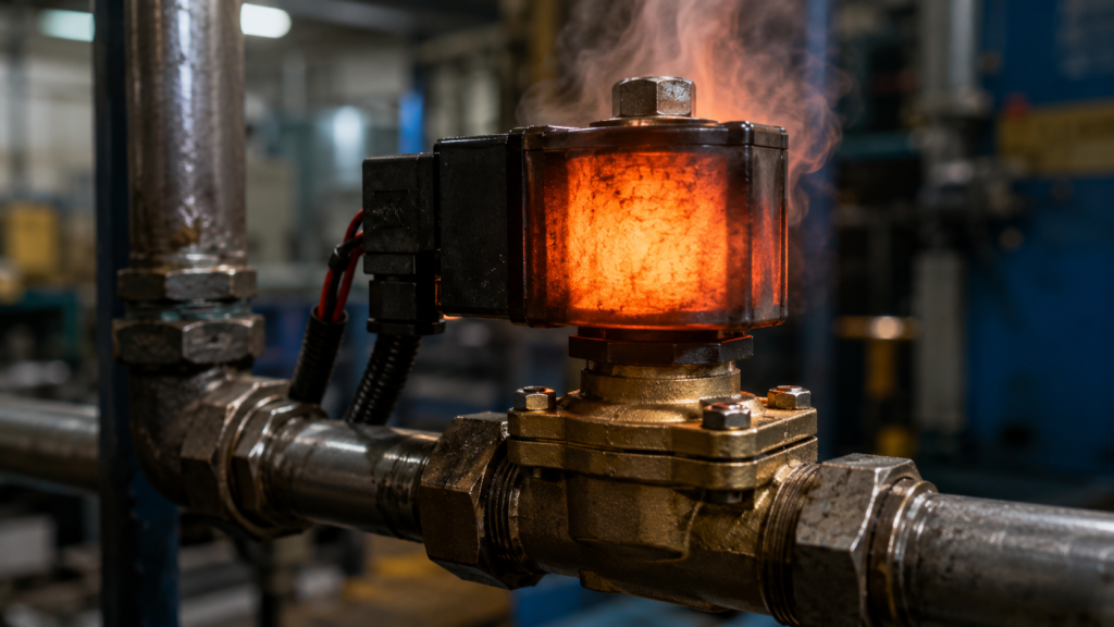
A solenoid valve operates normally, but after being energized for a while, its coil becomes surprisingly hot.
Sometimes it is warm enough that you can barely keep a finger on it. Naturally, that raises an uncomfortable question:
Is the valve about to burn out?
Not necessarily.
A solenoid valve coil gets hot because electrical current flows continuously through many turns of fine copper wire. The winding has resistance, so part of the electrical energy is converted into heat. Many continuous-duty solenoid coils are designed to remain energized for long periods and may become too hot to touch comfortably while still operating within their approved temperature limits.
Heat becomes a warning sign when the temperature is higher than expected, continues increasing, appears alongside a burning smell or is caused by incorrect voltage, a jammed AC armature, excessive duty cycle or restricted cooling.
A hot coil may be normal.
A smoking coil is considerably less open to interpretation.
How a Solenoid Valve Works
A solenoid valve converts electrical energy into mechanical movement.
Its main electromagnetic parts include:
- A coil of insulated copper wire
- A stationary magnetic core
- A movable plunger or armature
- An armature tube
- A return spring
- The valve’s internal sealing mechanism
When voltage is applied to the coil, current produces a magnetic field.
That magnetic field pulls the ferromagnetic armature toward the fixed core. The armature movement opens or closes a pilot orifice, valve seat or spool arrangement.
A simplified sequence is:
Voltage applied
↓
Current flows through the coil
↓
Magnetic field develops
↓
Armature moves
↓
Valve changes position
When the coil is de-energized, the magnetic field collapses and a spring normally returns the valve to its resting position.
The electromagnetic movement may last only a fraction of a second.
The coil current, however, may continue for as long as the valve remains energized.
Why the Coil Produces Heat
Copper is an excellent electrical conductor, but it still has resistance.
When current flows through the winding, electrical power is converted into heat:
P = I²RWhere:
Pis heat-producing powerIis coil currentRis winding resistance
For a simple resistive DC coil, power can also be considered as:
P = V × Ior:
P = V² ÷ RA coil rated at 6 W is continuously converting approximately six joules of electrical energy into magnetic work and heat every second while energized.
Only a small part of that energy is needed to move the armature during switching. Once the armature has moved, a conventional coil usually continues drawing holding power until voltage is removed.
That energy has to go somewhere.
Most of it eventually becomes heat.
Continuous Coil Current
A normally closed valve may need its coil energized for hours to remain open.
A normally open valve may need continuous power to remain closed.
Unless the valve uses a latching mechanism or electronic power-reduction circuit, current continues flowing through the coil throughout that energized period.
The coil temperature rises until the generated heat roughly equals the heat being released into:
- The surrounding air
- The metal armature tube
- The valve body
- Connected pipework
- The controlled fluid
- Nearby machine structures
At that point, the coil reaches thermal equilibrium and its temperature should stabilize.
Parker states that continuously energized solenoid coils become hot during extended operation and that continuous-duty coils are designed to operate under those conditions. It identifies smoke or the smell of burning insulation as indications of excessive heating rather than normal warmth.
A Hot Coil Can Be Completely Normal
People often judge electrical equipment using hand temperature.
That is unreliable.
Human skin begins finding surfaces uncomfortable at temperatures far below the maximum permissible temperature of many industrial coil-insulation systems.
A coil can therefore feel alarmingly hot while remaining within:
- Its winding-insulation rating
- Its enclosure-material rating
- Its permitted temperature rise
- Its specified ambient-temperature range
ASCO documentation notes that a solenoid energized for a long period can become hot enough to be touched only briefly while still remaining at a safe operating temperature. It similarly identifies smoke and burning-insulation odour as signs of abnormal heating.
The correct question is not:
“Does this feel hot?”
It is:
“Is this temperature permitted for this exact coil under these operating conditions?”
Temperature Rise Is Not the Same as Coil Temperature
Manufacturers may specify a temperature rise rather than only an absolute surface temperature.
Temperature rise is the increase above ambient temperature:
Coil temperature rise
=
Coil temperature − Ambient temperature
Suppose a coil operates with a 55°C rise.
In a 20°C room:
20°C + 55°C = 75°CIn a 45°C machine enclosure:
45°C + 55°C = 100°CThe same coil power produces a much higher final temperature in the hotter enclosure.
The actual temperature also depends on:
- Coil construction
- Insulation class
- Enclosure design
- Valve-body temperature
- Air movement
- Nearby energized coils
- Energization time
- Fluid temperature
This is why a valve that operates reliably in an open workshop may overheat when installed inside a hot, sealed cabinet.
The coil did not change.
Its ability to lose heat did.
Do Not Rely on a Universal “Normal” Temperature
There is no single temperature that applies to every solenoid valve.
One low-power pneumatic coil may run only slightly above ambient temperature.
A conventional industrial process-valve coil may become considerably hotter.
Coils are manufactured with different:
- Wattages
- Insulation classes
- Enclosures
- Encapsulation materials
- Ambient-temperature limits
- Hazardous-area ratings
- Duty ratings
Some modern valves use power-saving electronics and generate very little temperature rise. Others are designed to operate safely at temperatures that would feel extremely hot to a person.
Check:
- The coil nameplate
- Valve datasheet
- Manufacturer’s instructions
- Permitted ambient temperature
- Permitted media temperature
- Insulation class
- Duty-cycle rating
A temperature copied from another valve model is not a specification for yours.
What Is Coil Duty Cycle?
Duty cycle describes how long a coil may remain energized compared with the complete operating cycle.
It is commonly expressed as a percentage:
Duty cycle
=
Energized time ÷ Total cycle time × 100%
For example, if a coil is energized for 30 seconds and then de-energized for 30 seconds:
30 ÷ 60 × 100% = 50% duty cycleA 100% duty-cycle coil is intended for continuous energization under its specified environmental conditions.
An intermittent-duty coil is expected to receive cooling periods.
Parker specifies that many of its standard valves use coils designed for continuous, 100% duty, while also requiring appropriate ventilation and operation within the valve’s stated temperature limits.
Do not assume every solenoid coil is continuous-duty simply because it fits onto a valve.
Excessive Duty Cycle
An intermittent-duty coil can overheat when it is energized longer or more frequently than intended.
Possible causes include:
- A PLC output remaining on continuously
- Incorrect timer logic
- A machine stopping while the valve remains energized
- A failed limit switch
- A stuck relay contact
- Excessive cycling
- An incorrectly selected replacement coil
- A change in machine operation
The valve may have worked correctly in the original process because it was energized for only two seconds at a time.
After a software change, it may remain powered for twenty minutes.
Electrically, the coil is the same.
Thermally, it is now doing a very different job.
Rapid Cycling Can Also Add Heat
A continuous-duty rating does not automatically mean unlimited switching frequency.
Every energization may involve:
- Magnetic losses
- Mechanical impact
- AC inrush current
- Eddy-current losses
- Contact switching
- Movement of the armature
Very rapid cycling can increase average heat and accelerate wear in both the electrical and mechanical parts of the valve.
The permitted switching frequency depends on the valve design.
A small pneumatic valve built for high-speed automation may tolerate rapid switching.
A large process valve with a heavy armature may not.
Check the manufacturer’s maximum cycle rate instead of assuming that every click represents healthy enthusiasm.
Incorrect Coil Voltage
Every coil is designed for a particular supply.
Typical markings include:
24 V DC

24 V AC 50/60 Hz

120 V AC 60 Hz

230 V AC 50/60 Hz
Applying the wrong voltage can prevent correct operation or destroy the winding.
Common mistakes include:
- Applying 230 V to a 24 V coil
- Installing a 12 V coil in a 24 V system
- Connecting AC to a DC-only coil
- Connecting DC to an AC-only coil
- Using the wrong AC frequency
- Supplying excessive voltage from an unregulated source
- Assuming two physically identical coils have the same rating
Coil housings often look interchangeable.
Their internal windings may be completely different.
Why Overvoltage Overheats a DC Coil
Once a DC coil reaches steady state, its current is mainly limited by winding resistance.
A simplified calculation is:
I = V ÷ RBecause heating is:
P = V² ÷ Ra modest voltage increase can create a much larger power increase.
Suppose a 24 V DC coil has a resistance of 96 Ω.
At its rated voltage:
P = 24² ÷ 96

P = 6 W
If it is accidentally supplied with 30 V:
P = 30² ÷ 96

P = 9.375 W
The voltage increased by 25%.
The heating power increased by more than 56%.
The coil may operate initially, but its temperature can rise well beyond its intended value.
ASCO publishes defined operating-voltage ranges for individual coils and warns against operation outside approved limits. It also treats conversion between AC and DC versions as a manufacturer-specific change rather than a simple rewiring exercise.
Low Voltage Can Cause Different Problems
Low voltage usually reduces current in a DC coil, but it also weakens the magnetic force.
The armature may:
- Fail to move
- Move only partly
- Operate slowly
- Chatter
- Drop out under pressure
- Switch intermittently
The machine controller may then leave the coil energized because the expected valve movement never occurs.
A weakly energized coil may not immediately produce more electrical heat than normal, but the valve can remain continuously powered while failing to complete its mechanical action.
With an AC coil, low voltage can be more dangerous because failure to pull the armature fully into position may leave the coil near its high-current inrush condition.
AC and DC Coils Do Not Behave the Same Way
AC and DC coils may perform the same mechanical job, but their electrical behaviour is different.
DC coil
A DC coil’s steady-state current is governed mainly by winding resistance.
After the brief switching transient:
Current ≈ Voltage ÷ ResistanceThe current remains comparatively steady whether the armature is seated or slightly displaced, although the magnetic force and transient response change with the air gap.
AC coil
An AC coil has both resistance and inductive reactance.
Its current depends strongly on the magnetic circuit and the armature position.
When the armature is away from the fixed core, the magnetic air gap is large. Coil inductance is relatively low, so current is high.
When the armature pulls in and closes the gap, inductance increases and current falls to a lower holding value.
Bürkert explains that an AC solenoid consumes considerably more power at switch-on, when the air gap is at its maximum, than after the armature has been pulled into position.
AC Coil Inrush Current
The initial high current in an AC solenoid is called inrush current or pickup current.
The normal sequence is:
AC voltage applied
↓
Large armature air gap
↓
Low inductive impedance
↓
High inrush current
↓
Armature pulls in
↓
Air gap becomes small
↓
Inductance increases
↓
Current falls to holding level
That high current is expected for a very short time.
The coil is designed to tolerate it while the armature moves promptly.
If the armature does not move—or does not seat completely—the high current continues.
Then an AC coil can overheat extremely quickly.
Why a Jammed Armature Can Burn an AC Coil
The armature may fail to pull in because of:
- Dirt inside the armature tube
- Corrosion
- Bent mechanical parts
- Damaged seals
- Excessive fluid pressure
- Incorrect valve assembly
- Insufficient supply voltage
- A swollen or contaminated seal
- Mechanical wear
- A foreign object
- Incorrect coil or armature parts
With the air gap remaining open, the AC coil does not reach its normal high-inductance holding condition.
It continues drawing much more current than intended.
The sequence becomes:
Armature jams
↓
Magnetic air gap remains large
↓
AC current remains high
↓
Coil temperature rises rapidly
↓
Insulation degrades
↓
Coil burns out
Emerson’s service instructions include checking for a jammed core when troubleshooting solenoid problems.
This is why an AC valve that hums loudly but does not shift should be de-energized rather than allowed to “work itself free.”
It may work something free.
Quite possibly the smoke from its winding.
Never Energize an AC Coil Without Its Core
An AC coil should not normally be powered when it is removed from the valve’s armature tube or magnetic core assembly.
Without the iron core and completed magnetic circuit, its inductance can be far lower.
Current may then remain at a destructive level.
Bürkert specifically warns that AC coils have much lower resistance than equivalent DC coils and should never be operated without the solenoid core in place.
A technician may remove the coil during testing and energize it briefly to check whether it is magnetic.
With an AC coil, that “brief” test can damage it.
Use the manufacturer’s approved procedure instead.
What Happens When a DC Armature Jams?
A jammed DC armature is still a serious functional fault, but it does not normally cause the same sustained AC inrush phenomenon.
Once steady state is reached, DC current remains largely determined by the winding resistance.
The coil may continue drawing approximately its normal energized power even though the valve has not moved.
That can still cause problems:
- The coil remains hot continuously.
- The valve fails to control the process.
- The machine logic may repeatedly attempt operation.
- Pressure may remain trapped.
- The coil may overheat if it is not rated for continuous duty.
- Mechanical parts may be damaged by repeated attempts.
So a jammed DC valve is not harmless.
It is simply electrically different from a jammed AC solenoid.
AC Coils Need the Correct Frequency
An AC coil is designed for a stated frequency, commonly 50 Hz, 60 Hz or both.
Inductive reactance depends on frequency:
Xₗ = 2πfLLower frequency reduces inductive reactance and can allow more current to flow.
Using a 60 Hz-only coil on 50 Hz may therefore cause excessive current and heating, depending on the design.
A 50/60 Hz-rated coil has been designed for both frequencies within its specified voltage range.
Never assume that matching voltage alone is sufficient.
The full marking matters:
Voltage
+
AC or DC
+
Frequency
The coil does not regard the smaller print as optional.
AC Hum and Chattering
An AC solenoid may produce a faint hum during normal operation.
A loud buzz or mechanical chatter is different.
Possible causes include:
- Low voltage
- A dirty armature
- A damaged shading ring
- Incorrect frequency
- Excessive pressure
- Misaligned parts
- Loose coil hardware
- The armature failing to seat
Chattering repeatedly changes the magnetic air gap and can keep current above its normal holding value.
It also causes:
- Mechanical impact
- Contact wear
- Armature damage
- Heat
- Unstable valve operation
A louder-than-normal solenoid should be inspected before the coil becomes the machine’s least efficient space heater.
The Purpose of the Shading Ring
Many AC solenoids include a shading ring in the magnetic core.
AC current crosses zero twice during every electrical cycle. Without special design, the magnetic force would fall sharply at those moments and the armature could chatter.
The shading ring creates a phase-shifted magnetic component that helps maintain holding force as the main field passes through zero.
A damaged or missing shading ring can lead to:
- Buzzing
- Chattering
- Increased mechanical wear
- Unstable armature position
- Additional heat
DC coils do not require the same shading-ring arrangement because their magnetic field does not repeatedly reverse and cross zero in the same way. ASCO documentation distinguishes AC constructions containing shading coils from DC constructions, where they are not normally required.
Hot Fluid Can Heat the Coil
Not all coil temperature originates electrically.
The valve body may be controlling:
- Steam
- Hot water
- Heated oil
- Compressed gas
- Refrigerant
- Process chemicals
Heat can travel from the medium through the valve body and armature tube into the coil.
The final coil temperature is therefore influenced by both:
Electrical self-heating
+
Heat transferred from the process
A coil that operates safely on room-temperature compressed air may exceed its limit when fitted to a hot-water valve.
Valve selection must consider both ambient and media temperatures.
The electrical coil cannot be assessed separately from the hot piece of metal attached beneath it.
High Ambient Temperature
Solenoid datasheets specify maximum ambient temperature for a reason.
Inside an enclosure, the air may already be heated by:
- Power supplies
- Contactors
- VFDs
- Transformers
- Other solenoid coils
- Direct sunlight
- Poor ventilation
If the surrounding air is hot, the coil cannot release its own heat as easily.
A coil designed for continuous operation at 25°C ambient may operate very differently at 60°C.
Emerson product specifications show that permitted ambient ranges vary by coil construction and model, reinforcing the need to check the exact valve documentation rather than apply a universal value.
Coils Mounted Close Together
Valve manifolds may place many energized coils side by side.
Each coil heats the surrounding air and its neighbours.
The centre coils in a tightly packed manifold may operate hotter than the coils at the edges because they have:
- Less exposed surface
- Reduced airflow
- Heat arriving from both sides
- A warmer local ambient temperature
Some valve series are designed specifically for dense manifold installation and use low-power electronics.
Others require derating, reduced duty or additional ventilation.
A coil that is safe by itself may not behave identically while participating in a group sauna.
Power-Saving Coils
Some solenoid systems use a high initial current to pull the armature in and then electronically reduce the current needed to hold it.
This is sometimes called:
- Hit-and-hold control
- Peak-and-hold control
- Economy control
- Power-saving circuit
- Reduced holding power
The sequence is:
High initial power
↓
Armature moves
↓
Lower holding power
↓
Reduced coil temperature
Parker describes hit-and-hold electrical control as a way to reduce power consumption and heat generation in direct-acting solenoid applications.
Power-saving coils can be particularly useful in:
- Battery-powered equipment
- Compact manifolds
- Hot environments
- Continuously energized systems
- Applications sensitive to process heating
They still require correct voltage and wiring.
An electronic coil is not immune to enthusiastic misapplication.
Why a Coil May Become Hotter With Age
A healthy coil’s copper resistance normally increases as it warms, which tends to limit current somewhat.
Age-related problems elsewhere can nevertheless cause abnormal heat.
Examples include:
- Armature contamination
- Corroded moving parts
- Weak supply connections causing chatter
- Hardened seals
- Increased mechanical friction
- Failed power-saving electronics
- Moisture inside the coil
- Insulation deterioration
- Incorrect replacement parts
A valve that suddenly runs much hotter than it did for years deserves investigation.
“Solenoids run hot” is not a good explanation for a clear change in behaviour.
Signs of Impending Coil Failure
Disconnect the valve and investigate when you notice:
- A burning or varnish-like smell
- Smoke
- Melted or softened coil material
- Cracks in the encapsulation
- Brown or black discolouration
- Bubbling or deformation
- Coil temperature increasing more than before
- Loud AC buzzing or chatter
- Intermittent valve operation
- Delayed switching
- Repeated fuse or output-module faults
- The coil working only when cold
- The valve dropping out after warming
- Visible corrosion around the connector
- Moisture inside the electrical plug
- Damaged cable insulation
Parker identifies smoke and the odour of burning insulation as signs of excessive solenoid-coil heating that require attention.
Do not wait for the coil to become open circuit before calling it failed.
By that point, it has already submitted its resignation.
Why a Burning Smell Matters
A burnt smell may indicate that winding insulation or encapsulation material is decomposing.
Once insulation has been overheated, it may become:
- Brittle
- Carbonized
- Electrically leaky
- Less resistant to moisture
- Vulnerable to turn-to-turn short circuits
A partially shorted winding has fewer effective turns and often lower resistance.
That can increase current further, causing more heat and additional insulation damage.
The process can accelerate:
Insulation overheats
↓
Winding develops shorted turns
↓
Current increases
↓
More heat is produced
↓
Coil fails completely
A coil that smells burnt should not be allowed to cool and then returned to service without determining the cause.
Cooling removes temperature.
It does not rebuild insulation.
Shorted Turns
A solenoid winding contains many turns of thin insulated wire.
If insulation between neighbouring turns fails, part of the winding can become short-circuited.
The coil may still create enough magnetic force to operate temporarily, but its electrical characteristics have changed.
Possible symptoms include:
- Higher current
- Lower resistance
- Reduced magnetic force
- Rapid heating
- Unreliable operation
- Fuse failure
- Power-supply overload
An AC coil with shorted turns can become particularly hot because the damaged winding disrupts its intended impedance.
Measuring resistance may help identify a failed coil, but the result must be compared with manufacturer data or a known-good identical coil. Resistance varies with coil design and temperature.
A random resistance value found online is unlikely to diagnose a random valve correctly.
Open-Circuit Coil Failure
Eventually, excessive heat may break the winding completely.
The coil then becomes open circuit.
Typical symptoms include:
- No magnetic action
- No current
- Infinite or very high measured resistance
- A valve that remains in its de-energized position
- A PLC output appearing active while nothing moves
An open coil may be the final result of:
- Overvoltage
- Age
- Continuous overheating
- Mechanical damage
- Corrosion
- A failed internal thermal fuse
- A manufacturing defect
Replacing it without correcting the original cause may produce a second failed coil.
Two identical burnt coils are not bad luck.
They are a troubleshooting hint.
Moisture and Connector Problems
Coils with DIN connectors, flying leads or moulded plugs depend on correct sealing.
Moisture entering the connection can cause:
- Corrosion
- Leakage current
- Short circuits
- Intermittent voltage
- Heat at terminals
- Ground faults
- Electronic suppression-device failure
Check that:
- Connector gaskets are present
- Cable glands are tightened
- The cable diameter suits the gland
- The connector screw is secure
- The enclosure rating is appropriate
- Water cannot run directly along the cable into the connector
A coil may be blamed for heat that is actually being generated at a loose or corroded terminal.
Suppression Devices
DC solenoid coils produce an inductive voltage spike when de-energized.
Connectors or control circuits may include:
- Flyback diodes
- Zener diodes
- Varistors
- RC suppressors
- Transient-voltage suppressors
The suppression device must suit:
- AC or DC supply
- Coil voltage
- Required release speed
- PLC output type
- Polarity
A reverse-polarity connection can damage a connector containing an LED or diode even when the bare coil itself is non-polarized.
A failed suppression component may short the supply, overheat or prevent correct valve release.
Always check whether the coil connector contains electronics before treating it as two pieces of wire and a decorative light.
Why the Valve May Be Hot but Not Open
A hot coil proves only that electrical power is being consumed.
It does not prove that the valve moved.
The valve may remain closed or partly open because of:
- Jammed armature
- Insufficient pressure differential
- Incorrect flow direction
- Blocked pilot orifice
- Excessive pressure
- Damaged diaphragm
- Low voltage
- Wrong coil
- Contamination
- Incorrect assembly
Pilot-operated valves can require a minimum pressure differential to operate correctly.
The coil may pull the pilot armature normally while the main diaphragm or piston fails to move.
Do not diagnose a hot, non-flowing valve as “electrically fine” merely because the coil is magnetic.
The valve has both an electrical half and a fluid-mechanical half.
Either can spoil the afternoon.
A Safe Troubleshooting Sequence
Before inspecting the valve:
- Isolate electrical power.
- Lock out the supply where required.
- Verify that voltage is absent.
- Depressurize the fluid or pneumatic system.
- Allow the coil and valve body to cool.
- Follow the manufacturer’s maintenance instructions.
Parker instructs technicians to disconnect electrical power and depressurize the valve before servicing.
After isolation, check:
- Coil nameplate voltage
- AC or DC marking
- Frequency marking
- Duty-cycle rating
- Actual application temperature
- Connector condition
- Coil discolouration
- Armature freedom of movement
- Contamination
- Valve pressure limits
- Correct assembly
- Manufacturer part numbers
A qualified technician may also measure:
- Supply voltage during energization
- Coil current
- Coil resistance when isolated
- Voltage drop across control contacts
- Output voltage from the PLC or relay
Do not remove and energize an AC coil away from its magnetic core as a bench test.
Verify Voltage While the Coil Is Energized
A supply may measure correctly with no load and collapse when the coil energizes.
Possible causes include:
- Undersized power supply
- Long cable
- Loose terminal
- Corroded relay contact
- Overloaded PLC output
- Excessive simultaneous loads
- Incorrect transformer rating
For example:
Supply with coil off: 24 V

Supply with coil on: 17 V
That drop may prevent reliable pull-in and cause AC chatter or weak DC operation.
The voltage should be checked at the coil terminals under actual operating conditions by a person trained to perform energized measurements safely.
Measuring 24 V back at the power supply does not prove that 24 V reaches the valve.
The cable between them may have developed its own opinion.
Check the Mechanical Load
An electrically healthy coil may be unable to move the armature when the valve faces excessive pressure or mechanical resistance.
Confirm:
- Inlet pressure
- Outlet pressure
- Pressure differential
- Flow direction
- Media compatibility
- Fluid cleanliness
- Temperature
- Valve orientation, where specified
- Pilot-port condition
Do not repeatedly energize an AC coil against a jammed armature while investigating the fluid system.
Each attempt may hold it at high inrush current.
Find the cause with the power safely isolated.
Should You Replace Only the Coil?
Coils are replaceable on many solenoid valves.
Replacement may be reasonable when:
- The winding is open
- Insulation is visibly damaged
- The connector has failed
- The coil has the wrong voltage
- Testing confirms an electrical defect
But inspect the valve mechanism before installing the new coil.
If the original coil burned because the armature was jammed, a new AC coil may burn for exactly the same reason.
Also verify:
- Correct manufacturer
- Correct coil family
- Correct voltage
- Correct frequency
- Correct wattage
- Correct duty rating
- Correct temperature class
- Correct hazardous-area approval
- Correct enclosure rating
A coil that physically slides onto the tube is not automatically the correct replacement.
Shoes also fit onto hands with enough determination.
Common Solenoid-Heat Myths
“Any hot solenoid coil is failing”
No.
Continuous-duty coils may operate at temperatures that are uncomfortable to touch while remaining within their design limits.
“If the valve works, the voltage must be correct”
No.
An overvolted coil may continue operating while overheating and suffering accelerated insulation damage.
“AC and DC coils are interchangeable”
No.
Their winding resistance, magnetic design and operating behaviour differ. Use the exact type specified.
“A jammed armature only affects fluid flow”
Not with an AC coil.
Failure to pull in can leave the coil drawing high inrush current and cause rapid burnout.
“A continuous-duty coil can be used at any temperature”
No.
The rating applies only within specified ambient, media and installation conditions.
“Lower voltage protects the coil”
Not always.
Low AC voltage can prevent full armature pull-in, resulting in sustained high current and chatter.
“If the coil cools down, it is repaired”
No.
Overheated winding insulation may remain permanently damaged.
“A louder hum is normal as the valve gets older”
No.
New or increasing chatter can indicate low voltage, contamination, armature damage or shading-ring failure.
When Should the Coil Be Disconnected Immediately?
Switch off the valve when it is safe to do so if you notice:
- Smoke
- A burning smell
- Melting
- Rapidly increasing temperature
- Loud buzzing or violent chatter
- Repeated failure to shift
- Electrical arcing
- A hot or discoloured connector
- A tripped protective device
- Fluid leaking into the electrical assembly
Do not continue cycling the valve to see whether it improves.
Disconnect electrical power and isolate the process safely.
A coil that is producing smoke has already moved beyond the “monitor it for a while” stage.
Practical Diagnostic Checklist
When a solenoid valve coil gets hot, confirm:
- Is the coil rated for continuous duty?
- Is it energized continuously?
- Does its temperature stabilize?
- Is the ambient temperature within specification?
- Is the process fluid heating the valve body?
- Is the applied voltage correct?
- Is the supply AC or DC as marked?
- Is the AC frequency correct?
- Does the armature pull in completely?
- Is the valve buzzing or chattering?
- Is the mechanical core contaminated or jammed?
- Is the pressure within the valve rating?
- Are several coils heating one another?
- Is ventilation restricted?
- Is the connector loose, wet or corroded?
- Is there a burning smell or visible damage?
- Was the replacement coil the exact approved part?
A comparison with an identical healthy valve under the same load can be useful.
Just do not assume two coils are identical because both happen to be black and rectangular.
The Practical Answer
So, why does a solenoid valve coil get hot?
Because current flows continuously through a resistive copper winding while the valve remains energized.
That current produces heat. A continuous-duty coil is designed to reach an elevated operating temperature and may become uncomfortable to touch without actually being faulty.
Abnormal overheating is commonly caused by:
- Incorrect coil voltage
- Wrong AC or DC coil type
- Incorrect AC frequency
- An AC armature that cannot pull in
- A jammed or contaminated magnetic core
- Excessive duty cycle
- High ambient or fluid temperature
- Restricted ventilation
- Shorted winding turns
- Loose or damaged electrical connections
AC coils require particular attention.
They draw high current while the armature air gap is open. Once the armature seats, current falls to its holding value. If dirt, low voltage or mechanical damage prevents full movement, the coil may remain at high inrush current and burn out rapidly.
A hot but stable continuous-duty coil may be normal.
A coil that suddenly becomes hotter, buzzes loudly, smells burnt, discolours or stops operating reliably is warning that something has changed.
Disconnect it before the warning becomes smoke.