A star-delta starter is a traditional method used to reduce the starting current of a three-phase induction motor.
When a motor starts directly across the supply, it may draw several times its rated current. That inrush can cause voltage dips, stress contactors and cables, and place a sudden mechanical load on the driven equipment.
A star-delta circuit softens the start by initially connecting the motor windings in star, then changing them to delta once the motor has accelerated.
It is simpler and cheaper than a variable-frequency drive, although it provides only a fixed two-stage start rather than smooth speed and torque control.
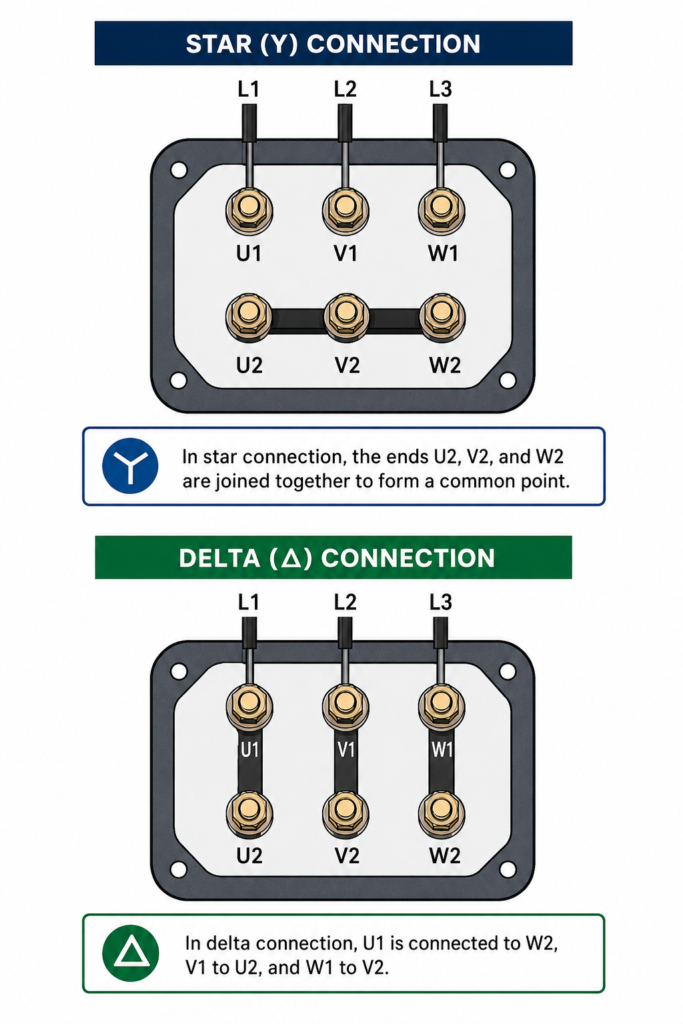
When Can Star-Delta Starting Be Used?
The motor must have six accessible winding terminals:
- U1
- V1
- W1
- U2
- V2
- W2
It must also be designed to run in delta at the available line voltage.
For example, a motor marked 400/690 V Δ/Y can normally run in delta on a 400 V supply and may therefore be suitable for star-delta starting.
A motor marked 230/400 V Δ/Y is normally operated in star on a 400 V supply. It should not be changed to delta on that same supply because each winding would receive excessive voltage.
Always check the motor nameplate before designing or wiring the starter.
Why the Motor Starts in Star
In the star connection, the ends of the three motor windings—U2, V2 and W2—are joined together.
The supply phases connect to U1, V1 and W1.
Each winding receives the phase voltage rather than the full line-to-line voltage:
Winding voltage = Line voltage ÷ √3
On a 400 V system:
400 ÷ 1.732 ≈ 230 V
Because the winding voltage is reduced, the motor draws less current during startup.
Compared with direct delta starting, the line starting current is approximately one-third. Starting torque is also roughly one-third because motor torque is proportional to the square of the applied voltage.
That reduction is useful for lightly loaded starts, but it creates an important limitation: a star-delta starter may struggle to accelerate machinery requiring high starting torque.
What Happens in Delta
Once the motor has accelerated, the star connection is removed and the windings are reconnected in delta.
In delta:
- U1 connects to W2
- V1 connects to U2
- W1 connects to V2
Each winding is connected between two supply phases and receives full line voltage.
The motor can then develop its normal operating torque and run at its rated load.
The changeover time is controlled by a timer. The correct delay depends on the motor, connected load and acceleration time. It should be long enough for the motor to approach normal speed, but not so long that it continues running in star under insufficient torque.
Main Components of a Star-Delta Starter
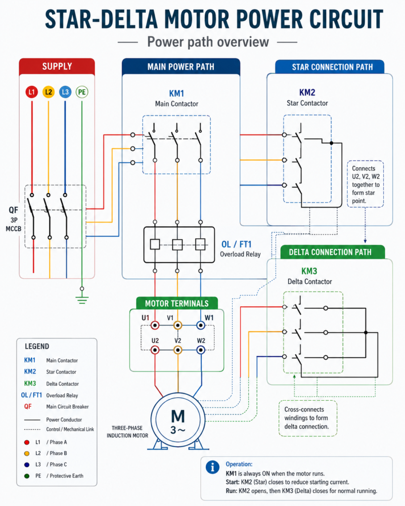
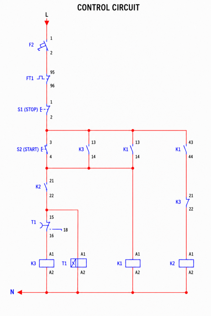
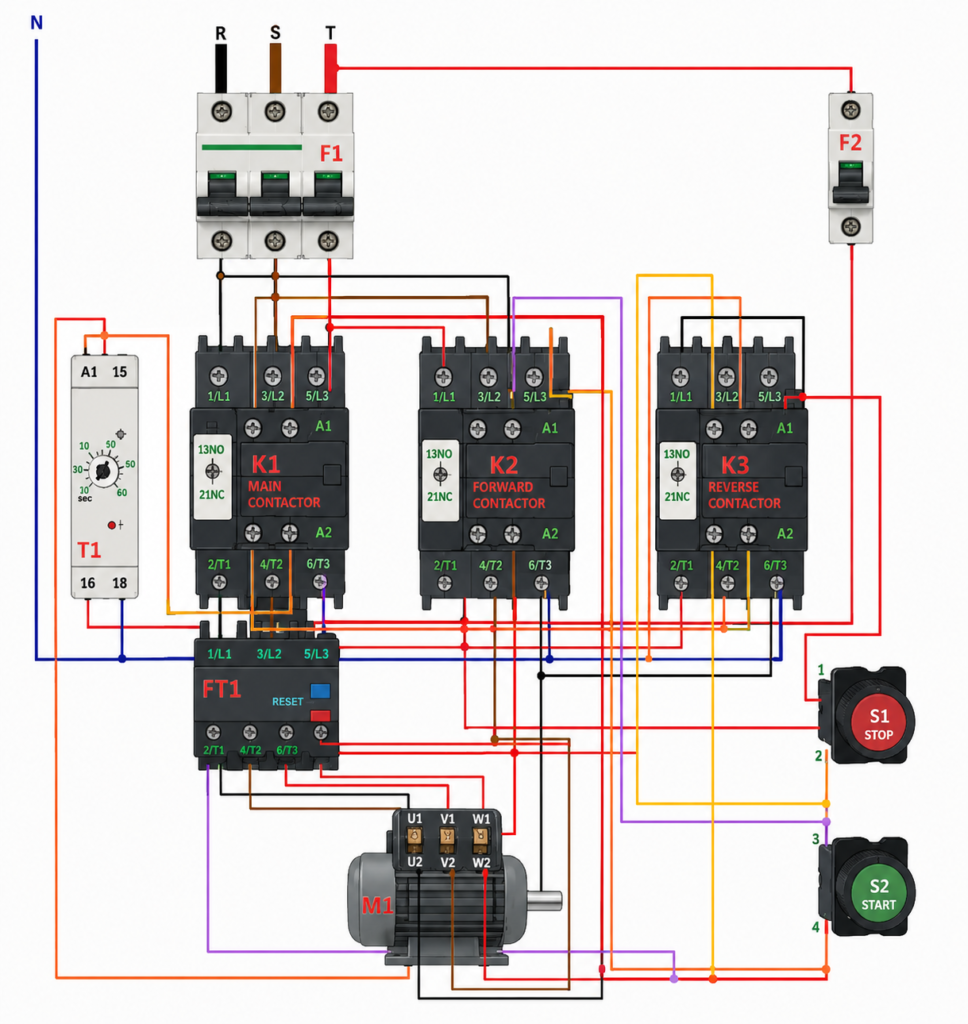
A typical circuit contains:
- Three-phase circuit breaker or motor-protection device
- Thermal overload relay
- Main contactor K1
- Delta contactor K2
- Star contactor K3
- Timer relay T1
- Normally closed STOP button
- Normally open START button
- Auxiliary contacts for holding and interlocking
- Six-terminal three-phase motor
The exact designations may differ, but the same component reference must be used consistently throughout the power and control drawings.
For example, every coil and contact belonging to the main contactor should be labelled K1.
Main Contactor K1
The main contactor remains energized during both starting and normal running.
Its purpose is to connect the three-phase supply to the upper motor terminals U1, V1 and W1.
When K1 drops out, power is removed from the complete motor circuit.
Star Contactor K3
The star contactor joins U2, V2 and W2 together during startup.
K3 is energized only while the motor is starting.
When the timer finishes, K3 must release before the delta contactor closes.
Delta Contactor K2
The delta contactor creates the cross-connections required for delta operation.
K2 is energized after the star contactor has opened. It remains energized together with K1 while the motor runs normally.
The star and delta contactors must never be closed simultaneously. Doing so can create a phase-to-phase short circuit through the contactor connections.
Timer Relay T1
The timer begins operating when the starter is activated.
During the starting period, its contact keeps K3 energized. After the preset time:
- The timer removes power from the star contactor.
- K3 opens.
- A short transition interval may occur.
- The timer energizes the delta contactor.
- K2 closes and the motor continues running in delta.
This arrangement is commonly called an open-transition star-delta starter because the motor is briefly disconnected during the changeover.
Starting Sequence
When the normally open START button is pressed, control voltage reaches:
- Main contactor K1
- Star contactor K3
- Timer relay T1
K1 closes its power contacts and connects the supply to U1, V1 and W1.
At the same time, K3 joins U2, V2 and W2 together. The motor windings are now connected in star, so the motor begins accelerating with reduced voltage, current and torque.
An auxiliary contact from K1 closes around the START button to form a holding circuit. The operator can therefore release the button while the starter remains energized.
Transition From Star to Delta
After the selected delay, timer T1 changes the state of its contacts.
The star contactor K3 de-energizes first. Its main contacts open and remove the star point.
Only after K3 has released should K2 energize.
The delta contactor then connects the winding ends to the appropriate opposite phases, forming the delta arrangement.
The motor now receives full winding voltage and continues running at normal torque.
A poorly timed transition can produce a noticeable current spike or mechanical shock. The timer setting should therefore be tested under realistic load rather than selected by guesswork.
Stopping the Motor
The STOP button is normally closed and wired in series with the control circuit.
When it is pressed:
- The control circuit opens.
- K1 de-energizes.
- K2 or K3 also loses power.
- The main power contacts open.
- The motor is disconnected from the supply.
The normally closed contact of the thermal overload relay is also placed in the control circuit. If the motor remains overloaded for too long, this contact opens and releases all contactors.
Electrical Interlocking
Electrical interlocking prevents the star and delta contactors from operating together.
A normally closed auxiliary contact from K2 is connected in series with coil K3.
A normally closed auxiliary contact from K3 is connected in series with coil K2.
Therefore:
- If K2 is energized, its NC contact blocks K3.
- If K3 is energized, its NC contact blocks K2.
The circuit should also use mechanical interlocking between the star and delta contactors where required. Electrical contacts can fail or be wired incorrectly; a mechanical interlock provides an additional physical barrier against simultaneous closure.
Why the Main Contactor Must Remain Energized
K1 supplies the motor throughout both operating stages.
If K1 drops out because of:
- STOP-button operation
- Overload trip
- Emergency-stop action
- Loss of control voltage
- Safety-circuit interruption
the complete starter shuts down.
Neither the star nor delta contactor should be capable of operating the motor independently of K1.
Advantages of Star-Delta Starting
A correctly applied star-delta starter offers several advantages:
- Lower starting current than direct-on-line starting
- Reduced voltage dip on the electrical supply
- Less mechanical shock during startup
- Relatively simple components
- Lower cost than electronic soft-starting equipment
- Easy maintenance with standard contactors and timers
Limitations
Star-delta starting is not suitable for every application.
Its main disadvantages include:
- Starting torque is reduced to roughly one-third.
- The motor must have six accessible terminals.
- The motor must be rated to run in delta at the supply voltage.
- Changeover may create a current and torque transient.
- It does not provide variable speed.
- Three contactors and additional wiring are required.
- Incorrect interlocking can cause a severe short circuit.
Loads such as heavily loaded conveyors, crushers or high-pressure compressors may not accelerate adequately in star.
A soft starter or VFD may be more appropriate when smoother acceleration, greater starting torque or speed control is required.
Common Star-Delta Starter Faults
If the motor does not start, check the control supply, overload contact, STOP button, START button and K1 coil.
If it starts in star but stops during transition, investigate:
- Timer contact operation
- Delta contactor coil
- Interlocking contacts
- Incorrect motor-terminal wiring
- Excessive mechanical load
- Timer setting that is too short
If the circuit breaker trips during changeover, immediately check:
- Star and delta contactors closing together
- Incorrect delta wiring
- Failed mechanical interlock
- Welded contactor contacts
- Wrong motor terminal identification
Do not repeatedly reset and restart the circuit until the wiring has been verified.
Final Thoughts
A star-delta starter reduces motor starting current by first connecting the windings in star and later changing them to delta.
K1 acts as the main contactor, K3 forms the temporary star point, K2 creates the delta connection and T1 controls the transition.
The circuit is effective only when the motor is suitable, the six terminals are identified correctly and the star and delta contactors are securely interlocked.
When those conditions are met, star-delta starting remains a practical and economical solution for many three-phase motor applications.