A strain sensor is used to measure very small deformation in a machine part, frame, press, shaft, structure, or mechanical component.
In automation, strain sensors are often used for indirect force measurement.
This means the sensor does not always measure force directly. Instead, it measures how much a machine part stretches, compresses, bends, or deforms. From that strain value, the control system can estimate force.
When a strain sensor gives wrong readings, the problem can come from many places:
Sensor damage
Loose mounting
Bad cable
Wrong amplifier settings
Incorrect PLC scaling
Mechanical overload
Temperature drift
Poor grounding
Broken strain gauge bridge
Wrong excitation voltage
Bad 4–20 mA signal
Incorrect calibration
Machine frame changes
Moisture inside connector
Electrical noise from motors or VFDs
So the best way to diagnose a strain sensor is to separate the problem into sections:
Mechanical problem
Sensor problem
Cable problem
Amplifier problem
PLC input problem
Calibration problem
Process problem
Do not replace the sensor immediately. First, test the system step by step.
Important Safety Note
Strain sensors are often installed on machines that apply large forces.
Before troubleshooting:
Lock out the machine if needed.
Do not place hands near moving machine parts.
Do not test during press movement unless you are trained and authorized.
Do not overload the machine just to test the sensor.
Do not disconnect sensor cables while the system is running unless safe to do so.
Do not use an insulation tester on amplifier electronics or PLC inputs.
Always check the sensor manual before applying test voltages.
Also, if the sensor is used for machine safety, overload protection, or critical process control, do not bypass it casually. Follow the machine safety procedure.
How a Strain Sensor Should Work
A strain sensor detects small deformation.
The basic chain is:
Force is applied to the machine structure.
The structure slightly deforms.
The strain sensor follows this deformation.
The strain gauge inside the sensor changes resistance.
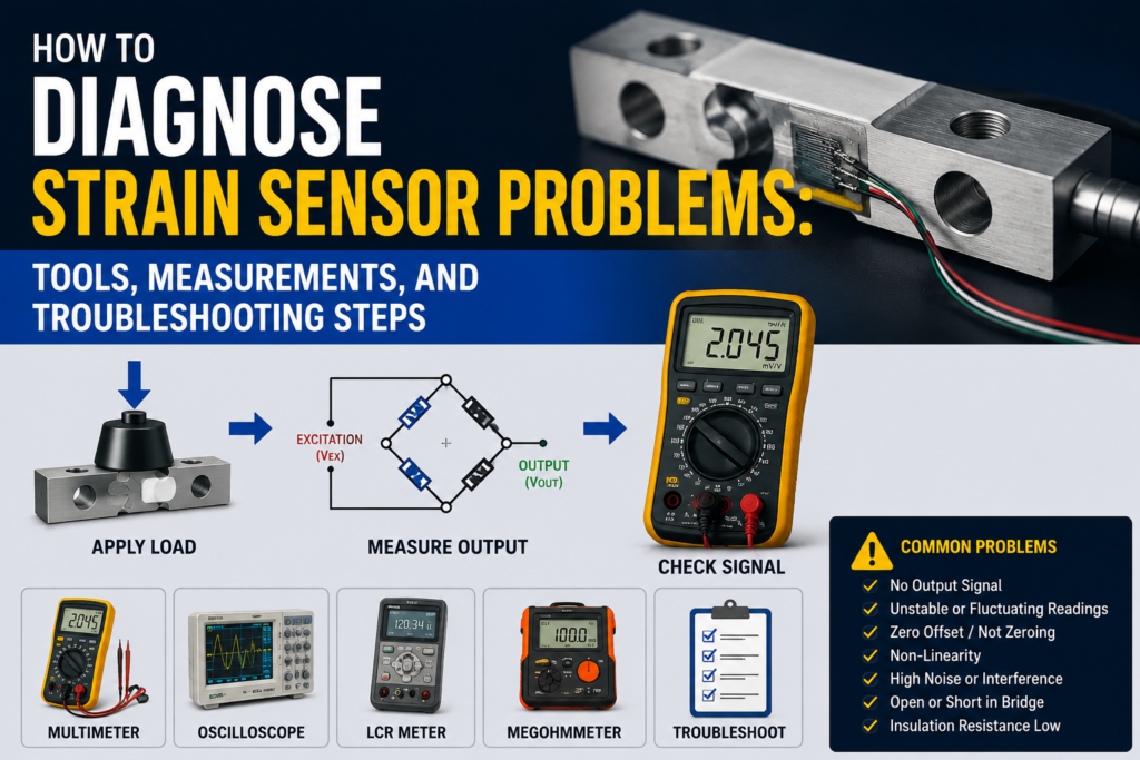
A Wheatstone bridge converts the resistance change into a small voltage signal.
An amplifier converts the signal into 4–20 mA, 0–10V, mV/V, or digital data.
The PLC or controller scales the signal into strain, force, pressure, load, or machine force.
The important point is this:
A strain sensor normally measures deformation first. Force is calculated or calibrated from that deformation.
So if the mechanical structure changes, the force reading can change even if the sensor is healthy.
First Question: What Type of Strain Sensor Do You Have?
Before measuring anything, identify the sensor type.
There are two common types:
Passive strain sensor
Active / amplified strain sensor
Passive Strain Sensor
A passive strain sensor usually has a raw strain gauge bridge inside.
It may output a small signal like:
0.5 mV/V
1.0 mV/V
2.0 mV/V
3.0 mV/V
This type needs a strain gauge amplifier.
A normal PLC analog input usually cannot read this signal directly because the signal is too small.
Active Strain Sensor
An active strain sensor has built-in electronics.
It may output:
4–20 mA
0–10V
±10V
IO-Link
CANopen
Digital signal
Fieldbus signal
This type is easier to connect to a PLC.
When troubleshooting, the tests are different.
For a passive sensor, you test bridge resistance, excitation voltage, mV signal, insulation, and amplifier.
For an active sensor, you test power supply, output signal, scaling, and communication.
Tools Needed for Strain Sensor Troubleshooting
1. Digital Multimeter
This is the first tool to use.
Use it to check:
Power supply voltage
Excitation voltage
Output voltage
4–20 mA current
Cable continuity
Bridge resistance
Connector problems
Ground faults
Loose terminals
A good multimeter is enough for many basic checks.
2. Process Meter / Loop Calibrator
Very useful for 4–20 mA systems.
Use it to:
Measure the sensor output current
Simulate 4–20 mA into the PLC input
Check PLC scaling
Check if the PLC input is correct
Source a test signal
If the sensor display or amplifier value is correct but the PLC value is wrong, a loop calibrator is one of the best tools.
3. Strain Gauge Amplifier / Indicator
Useful for passive mV/V sensors.
A strain gauge amplifier supplies excitation voltage and reads the bridge signal.
Use it to check:
Raw sensor response
Zero balance
mV/V output
Bridge signal stability
Calibration response
Shunt calibration
Sensor sensitivity
4. Precision mV Meter
A normal multimeter may not be good enough for very small mV/V signals.
A precision meter can help measure:
Bridge output in millivolts
Zero offset
Small signal changes under load
For example, a 2 mV/V sensor with 10V excitation only gives 20 mV at full scale.
That is a very small signal.
5. Insulation Tester
Use carefully.
It can help detect:
Moisture in cables
Damaged insulation
Sensor body short
Cable shield faults
Water inside connectors
But never use it on connected electronics.
Disconnect the sensor from the amplifier or transmitter first.
Use only the test voltage allowed by the manufacturer.
6. Oscilloscope
Useful when the reading is noisy or unstable.
Use it to check:
Electrical noise
Signal spikes
Interference from VFDs
Power supply ripple
Grounding issues
Unstable amplifier output
This is not always needed, but it is very helpful for difficult faults.
7. Reference Load or Reference Force Sensor
Useful for checking calibration.
Use:
Known weight
Reference load cell
Calibrated force sensor
Hydraulic pressure reference
Known machine force
Test fixture
If you apply a known load and the strain sensor reading is wrong, you can find calibration or mechanical problems.
8. Torque Wrench / Torque Screwdriver
Very important for screw-on strain sensors.
Use it to check:
Mounting screw torque
Correct tightening
Repeatable sensor mounting
Loose sensor problems
A strain sensor that is not mounted correctly can give bad readings even if it is electrically perfect.
9. Dial Indicator or Mechanical Measurement Tool
Useful for checking whether the machine part actually moves or deforms.
Sometimes the sensor is fine, but the structure is not deforming as expected.
10. Temperature Meter
Useful for checking temperature drift problems.
Strain sensors can be affected by:
Machine heating
Sunlight
Hydraulic oil temperature
Motor heat
Ambient temperature changes
Uneven temperature across the structure
Common Fault Symptoms
Common strain sensor problems include:
No signal
Signal stuck at zero
Signal stuck at maximum
4–20 mA output stuck at 4 mA
4–20 mA output stuck at 20 mA
Output below 4 mA or above 20 mA
Signal jumps randomly
Force value drifts over time
Zero point changes every cycle
Measurement is not repeatable
Reading changes with temperature
Reading is too high
Reading is too low
Sensor responds in the wrong direction
PLC value does not match amplifier value
Machine force is present but sensor does not respond
Sensor overload alarm
Bridge error
Cable break alarm
Each symptom points to a different area.
Step 1: Visually Inspect the Sensor and Cable
Start with simple inspection.
Check:
Is the sensor physically damaged?
Is the cable crushed or cut?
Is the connector loose?
Is there oil, water, or dirt in the connector?
Are mounting screws tight?
Is the sensor mounted on a clean flat surface?
Is the cable pulled tight?
Is the cable shield connected correctly?
Is the cable routed near motor/VFD cables?
Is the sensor installed in the correct direction?
Many strain sensor faults are mechanical or wiring-related.
Do not skip this step.
Step 2: Check Sensor Mounting
For screw-on strain sensors, mounting is critical.
A strain sensor must follow the deformation of the machine structure. If it is loose, twisted, badly aligned, or mounted on a poor surface, the measurement will be wrong.
Good Mounting
Clean mounting surface
Flat surface
Correct screw torque
Sensor mounted in correct direction
No paint, rust, or dirt under sensor if not allowed
Cable strain relief installed
Sensor not mechanically stressed by cable pull
Mounting area actually deforms under load
Bad Mounting
Loose screws
Uneven surface
Paint layer under sensor
Rust or dirt under sensor
Wrong mounting direction
Sensor mounted on a non-representative area
Cable pulling on sensor
Sensor installed near cracks or weld distortion
Sensor mounted after mechanical structure was modified
A sensor can pass all electrical tests and still give wrong readings if it is mounted badly.
Step 3: Check Power Supply
For active sensors and amplifiers, check power supply voltage.
Many industrial sensors use 24V DC.
Typical Good 24V DC Reading
For many industrial devices:
20.4V DC to 28.8V DC is usually acceptable.
That is 24V ±20%.
Always check the manual.
Bad Readings
0V
Wrong polarity
Below 20V
Unstable voltage
Voltage drops during machine movement
High AC ripple on DC supply
Loose 0V/common connection
Shared power supply overloaded
If the amplifier resets, signal jumps, or output drops randomly, unstable power supply is a possible cause.
Measure voltage while the sensor and amplifier are connected, not only with the wires disconnected.
Step 4: Check Excitation Voltage for Passive Sensors
Passive strain sensors need excitation voltage from the amplifier.
Common excitation values include:
2.5V
5V
10V
12V
The exact value depends on the amplifier and sensor.
Measure excitation voltage between the excitation wires.
Common wire names:
EX+ and EX-
Excitation + and excitation –
Supply + and supply –
Bridge + and bridge –
Good Reading
Excitation voltage matches amplifier setting.
Examples:
5.00V if amplifier is set to 5V
10.00V if amplifier is set to 10V
A small tolerance is normal.
Bad Reading
0V excitation
Wrong excitation voltage
Unstable excitation
Voltage changes when cable is moved
Excitation shorted
Wrong wiring to signal wires
Amplifier not supplying bridge power
If there is no excitation voltage, a passive strain gauge bridge cannot produce a correct signal.
Step 5: Check Bridge Resistance
For passive strain gauge sensors, bridge resistance is one of the most useful tests.
Common bridge resistances are:
120 Ω
350 Ω
700 Ω
1000 Ω
Many industrial strain gauge sensors use 350 Ω, but this is not universal.
Check the datasheet.
How to Measure Bridge Resistance
Disconnect the sensor from the amplifier.
Measure resistance between excitation wires.
Then measure resistance between signal wires if the manual allows.
Typical wire names:
EX+ to EX-
SIG+ to SIG-
OUT+ to OUT-
Good Reading
Bridge resistance close to datasheet value.
Example:
350 Ω sensor may measure around 350 Ω
1000 Ω sensor may measure around 1000 Ω
Some tolerance is normal.
Bad Reading
OL / open circuit
Near 0 Ω
Very different from datasheet
Reading jumps when cable is moved
Different resistance at connector and at cable end
Short between signal and shield
Short to sensor body
If bridge resistance is open, the strain gauge or cable is likely broken.
If resistance is near zero, there may be a short circuit.
Step 6: Check Each Wire for Continuity
If the sensor has a cable or connector, check continuity from the sensor side to the amplifier side.
Good
Each wire has low resistance from end to end.
Usually:
Below 1–2 Ω for short cables
A few ohms may be normal for long cables
Bad
Open wire
Intermittent wire when cable is moved
High resistance connection
Short between wires
Short to shield
Short to sensor body
Move the cable gently while measuring.
If the resistance jumps, the cable or connector may be damaged.
Step 7: Check Insulation Resistance
Insulation testing helps find moisture, damaged cable, or internal leakage.
But be careful.
Important
Disconnect the sensor from electronics first.
Do not insulation-test into PLC inputs, amplifiers, or active sensor electronics.
Use the test voltage recommended by the sensor manufacturer.
For some strain gauge sensors, high test voltage may not be allowed.
What to Test
Depending on sensor type:
Signal wires to shield
Excitation wires to shield
Bridge wires to sensor body
Wires to machine ground
Cable shield to conductors
General Practical Values
| Insulation Resistance | Meaning |
|---|---|
| >100 MΩ | Very good |
| 20–100 MΩ | Usually acceptable, but check manual |
| 1–20 MΩ | Suspicious |
| <1 MΩ | Usually bad |
Low insulation can cause:
Drift
Noise
Wrong zero
Unstable reading
Temperature-dependent faults
Random output jumps
Water inside connectors is a common cause.
Step 8: Check Zero Balance
Zero balance tells you the sensor output when there is no load or no strain condition.
For passive sensors, this is usually measured in mV/V.
For active sensors, it may be shown as mA, volts, strain value, or force value.
Passive Sensor Example
A 2 mV/V sensor with 10V excitation has full-scale output of 20 mV.
At zero load, the output should usually be close to zero, but some offset is normal.
Good
Stable zero reading
Zero offset within datasheet limit
Zero returns after load is removed
No large drift over time
Bad
Very large zero offset
Zero keeps drifting
Zero changes every cycle
Zero jumps when cable is moved
Zero changes when machine vibrates
Zero does not return after load removal
Large zero offset can be caused by:
Sensor overload
Bad mounting
Mechanical stress
Cable fault
Moisture
Bridge damage
Amplifier offset
Incorrect tare/zero setting
Step 9: Check Raw mV/V Output
For passive sensors, the raw output is very small.
Typical strain sensor output can be around:
0.4 mV/V
1.0 mV/V
2.0 mV/V
3.0 mV/V
This means output per volt of excitation.
Example
Sensor sensitivity:
2 mV/V
Excitation:
10V
Full-scale output:
2 × 10 = 20 mV
So at full scale, you only get 20 mV.
At 50% load, you expect about 10 mV.
At 25% load, you expect about 5 mV.
Good mV Signal
Signal changes smoothly when load changes
Signal returns close to zero when load is removed
Signal polarity matches load direction
Signal is proportional to applied load
No random jumps
No large noise
Bad mV Signal
No change under load
Output saturated
Output reversed unexpectedly
Signal jumps when cable moves
Large noise
Drift while load is constant
Output does not return to zero
Signal changes when tapping connector or cable
If the mV signal is good but PLC value is wrong, the sensor is probably okay. The problem is likely amplifier scaling or PLC scaling.
Step 10: Check 4–20 mA Output
Many active strain sensors or strain amplifiers output 4–20 mA.
For a normal unidirectional range:
| Sensor Value | Expected Current |
|---|---|
| 0% | 4 mA |
| 25% | 8 mA |
| 50% | 12 mA |
| 75% | 16 mA |
| 100% | 20 mA |
Example:
If the system is scaled:
0 kN = 4 mA
100 kN = 20 mA
Then:
50 kN = 12 mA
Good 4–20 mA Reading
Around 4 mA at zero load
Around 12 mA at half range
Around 20 mA at full range
Signal changes smoothly with load
PLC value matches measured current
Bad 4–20 mA Reading
| Reading | Possible Problem |
|---|---|
| 0 mA | Broken loop, no power, wrong wiring |
| 3.6 mA or lower | Fault alarm on many devices |
| 4 mA all the time | No load, output stuck, wrong scaling, sensor not responding |
| 20 mA all the time | Overload, saturated output, wrong scaling |
| Above 21 mA | Fault alarm or overrange on many devices |
| Random jumping | Noise, loose wire, bad grounding, mechanical instability |
| Correct mA but wrong PLC value | PLC scaling problem |
| Correct sensor display but wrong mA | Output configuration problem |
Alarm current values depend on device settings. Always check the manual.
Step 11: Check 0–10V Output
Some sensors or amplifiers use voltage output.
For a 0–10V output:
| Sensor Value | Expected Voltage |
|---|---|
| 0% | 0V |
| 25% | 2.5V |
| 50% | 5V |
| 75% | 7.5V |
| 100% | 10V |
For a ±10V output:
Negative strain may be negative voltage.
Positive strain may be positive voltage.
Good
Stable voltage
Correct voltage for known load
Smooth change with load
Returns to zero or offset after load removal
Bad
0V all the time
10V all the time
Voltage above expected range
Negative voltage when not expected
Jumping signal
Voltage drops when connected to PLC
Correct output before PLC but wrong after connection
If the voltage is correct disconnected but wrong when connected to the PLC, check input impedance, wiring, and grounding.
Step 12: Compare Sensor/Amplifier Value With PLC Value
This is one of the most important tests.
Compare:
Sensor output
Amplifier display
Measured mA or voltage
PLC raw analog value
PLC scaled engineering value
HMI value
Example
Amplifier display shows:
50 kN
Output range:
0–100 kN = 4–20 mA
Expected current:
12 mA
PLC should show:
50 kN
If the measured current is 12 mA but the PLC shows 70 kN, the problem is PLC scaling, not the sensor.
Common PLC Scaling Mistakes
PLC set to 0–20 mA instead of 4–20 mA
Wrong engineering range
Wrong maximum force value
Wrong analog input channel
Wrong raw input range
Wrong units
Wrong offset
Signal inverted
Integer conversion mistake
HMI scaling different from PLC scaling
Wrong data register from fieldbus device
Always prove the signal before changing the sensor.
Step 13: Simulate the PLC Input
Use a loop calibrator or signal simulator.
Inject known signals into the PLC input.
For 4–20 mA:
| Simulated Signal | PLC Should Show |
|---|---|
| 4 mA | 0% |
| 8 mA | 25% |
| 12 mA | 50% |
| 16 mA | 75% |
| 20 mA | 100% |
For 0–10V:
| Simulated Signal | PLC Should Show |
|---|---|
| 0V | 0% |
| 2.5V | 25% |
| 5V | 50% |
| 7.5V | 75% |
| 10V | 100% |
If the PLC does not scale correctly with simulated signals, fix the PLC or HMI scaling first.
Step 14: Check Calibration
Strain sensors used for force measurement usually need calibration on the machine.
This is because the sensor measures local deformation, not force directly.
Good Calibration
Known force gives correct reading
Zero is stable
Span is correct
Reading is repeatable
Loading and unloading values are close
Calibration points are documented
Bad Calibration
Zero point wrong
Span wrong
Reading correct at low force but wrong at high force
Reading not repeatable
Different result after remounting sensor
Different result after machine repair
PLC scaling changed without recalibration
Mechanical structure changed
If a machine part was replaced, welded, reinforced, loosened, or cracked, calibration may no longer be valid.
Step 15: Check Repeatability
Repeatability means the sensor gives the same result when the same load is applied again.
Test
Apply the same load several times.
Example:
Apply 10 kN five times.
The reading should return close to the same value each time.
Good
Readings are consistent
Zero returns after load removal
Small variation only
Bad
Reading changes every cycle
Zero shifts after each load
Output slowly increases or decreases
Result depends on loading direction
Large difference between loading and unloading
Poor repeatability can be caused by:
Loose mounting
Mechanical play
Cracked structure
Sensor slipping
Cable movement
Hysteresis
Overload damage
Bad calibration
Temperature change
Step 16: Check Hysteresis
Hysteresis means the reading is different when approaching the same load from increasing force versus decreasing force.
Example:
At 50 kN while loading, sensor shows 50 kN.
At 50 kN while unloading, sensor shows 46 kN.
Some hysteresis is normal in mechanical systems, but too much indicates a problem.
Possible causes:
Mechanical friction
Loose bolts
Machine frame movement
Sensor mounting issue
Plastic deformation
Overloaded structure
Poor sensor location
Mechanical play
Step 17: Check Temperature Drift
Strain measurement is sensitive to temperature.
Temperature can affect:
The sensor
The machine structure
The mounting surface
The cable
The amplifier electronics
The zero point
Good
Small drift within datasheet limits
Temperature compensation working
Signal stable after warm-up
Bad
Zero changes strongly with temperature
Reading changes when machine warms up
Sensor exposed to uneven heat
Cable routed near hot surface
Amplifier installed in hot cabinet
Sensor installed near motor or heater
If the reading slowly drifts during the day, check temperature.
A useful test is to record:
Sensor value
Machine temperature
Ambient temperature
Hydraulic oil temperature
Cabinet temperature
If the signal follows temperature, the issue may not be real force change.
Step 18: Check Electrical Noise
Strain signals are small, especially with passive bridge sensors.
Noise can cause unstable readings.
Common noise sources:
VFD motor cables
Servo drives
Welding machines
Large contactors
Solenoid valves
Poor grounding
Bad shield connection
Long sensor cables
Power cables routed with signal cables
Poor 24V power supply
Good
Stable signal
Low noise
Shield connected according to manual
Signal cable separated from power cables
No large spikes when motors start
Bad
Signal jumps when VFD starts
Spikes when contactor switches
Reading changes when motor speed changes
Noise visible on oscilloscope
Signal cable routed next to power cable
Shield disconnected or grounded incorrectly
For passive mV/V sensors, use proper shielded cable and correct grounding.
Step 19: Check Cable Shield and Grounding
Shielding is important for strain gauge signals.
Good
Shield connected according to manufacturer instructions
Usually shield connected at amplifier side or recommended point
Cable routed away from high-power cables
No ground loop
Sensor body properly mounted
Panel grounding good
Bad
Shield not connected
Shield connected at wrong places causing loop
Shield used as signal common
Broken shield
Sensor cable grounded through machine accidentally
High voltage between sensor ground and panel ground
Measure voltage between:
Sensor body and panel ground
Cable shield and panel ground
Machine frame and control cabinet PE
Ideally, ground voltage should be close to 0V.
If you see more than about 1V AC or DC between grounding points, investigate.
Step 20: Check Mechanical Overload
A strain sensor can be damaged if the machine structure is overloaded.
Overload may cause:
Permanent zero shift
Bridge damage
Mechanical deformation
Non-repeatable output
Hysteresis increase
Sensor housing damage
Mounting screw damage
Signs of Overload
Zero value changed permanently
Sensor output saturated
Sensor no longer returns to zero
Physical deformation visible
Calibration no longer valid
Output differs greatly from previous baseline
One direction works, other direction does not
If overload is suspected, compare zero and span with old maintenance records if available.
Step 21: Check Shunt Calibration
Some strain gauge amplifiers support shunt calibration.
Shunt calibration connects a known resistor across part of the bridge to simulate a known strain signal.
This checks:
Bridge wiring
Amplifier response
Signal path
Scaling stability
Good
Shunt calibration produces expected value
Repeated shunt test gives same result
Amplifier reacts correctly
Bad
No reaction to shunt
Wrong shunt value
Unstable response
Amplifier error
Wiring problem
Bridge problem
Shunt calibration does not fully prove mechanical calibration, but it is very useful for checking the electrical measurement chain.
Step 22: Check Communication or Digital Output
Some strain sensors use IO-Link, CANopen, Modbus, PROFINET, EtherNet/IP, or another protocol.
If the local sensor value is correct but PLC value is wrong, check communication mapping.
Common problems:
Wrong address
Wrong register
Wrong byte order
Wrong data type
Wrong scaling factor
Wrong units
Wrong parameter set
Communication timeout
Wrong device profile
PLC reads status word instead of measurement value
If possible, compare the value using manufacturer software or a diagnostic tool.
Step 23: Check Sensor Direction and Polarity
Strain can be positive or negative.
If the sensor is mounted in the wrong direction or wired with reversed signal polarity, the output may be inverted.
Good
Tension gives expected positive value
Compression gives expected negative value
PLC sign matches HMI sign
Alarm logic uses correct direction
Bad
Force increases but value decreases
Positive force shown as negative
Alarm works backwards
PLC value inverted
Sensor mounted 180° wrong
Signal wires reversed
This is common after replacing a sensor or rewiring a connector.
Troubleshooting by Symptom
1. No Output Signal
Possible causes:
No power supply
No excitation voltage
Broken cable
Open bridge
Wrong wiring
Damaged amplifier
Wrong PLC channel
Sensor disconnected
Checks:
Measure 24V supply
Measure excitation voltage
Check bridge resistance
Check cable continuity
Check amplifier status
Check PLC input wiring
2. Signal Stuck at Zero
Possible causes:
No mechanical strain
Sensor mounted in wrong position
Sensor loose
Low-flow or tare function active
PLC scaling issue
Broken bridge
Amplifier zeroed incorrectly
Wrong output range
Checks:
Apply known load safely
Check raw signal
Check mounting
Check tare/zero settings
Measure 4–20 mA or voltage output
Simulate PLC input
3. Signal Stuck at Maximum
Possible causes:
Overload
Output saturated
Bridge fault
Wrong amplifier range
Wrong calibration span
Shorted cable
PLC scaling problem
Sensor damaged
Checks:
Remove load safely
Check zero
Measure output current/voltage
Check bridge resistance
Check amplifier range
Check overload history
4. Reading Is Unstable
Possible causes:
Loose mounting
Vibration
Electrical noise
Bad shield
Cable damage
Loose connector
Poor grounding
Unstable power supply
Mechanical play
Temperature changes
Checks:
Check mounting screws
Move cable gently while watching signal
Check grounding
Check oscilloscope signal
Check power supply
Separate cable from VFD/motor cables
Increase filtering only after fixing real issues
5. Reading Drifts Over Time
Possible causes:
Temperature drift
Moisture
Sensor creep
Machine structure warming
Amplifier warm-up
Mechanical relaxation
Loose mounting
Hydraulic pressure changes
Checks:
Record temperature and signal
Check insulation resistance
Check zero after warm-up
Check mounting
Check if drift follows machine temperature
Check sensor environment
6. Reading Is Too High
Possible causes:
Wrong calibration span
Wrong PLC scaling
Sensor installed in more sensitive position
Mechanical structure changed
Signal range mismatch
Wrong units
Amplifier gain too high
Checks:
Compare measured output with amplifier value
Check calibration data
Apply known load
Check PLC scaling
Check sensor mounting location
7. Reading Is Too Low
Possible causes:
Loose mounting
Sensor not following deformation
Wrong sensor location
Amplifier gain too low
PLC range too large
Mechanical stiffness changed
Bad calibration
Sensor damaged
Checks:
Check mounting torque
Apply known load
Check raw mV/V signal
Check amplifier span
Check PLC scaling
Compare with reference load
8. PLC Value Wrong but Amplifier Value Correct
Possible causes:
PLC scaling error
Wrong analog input range
Wrong wire connection
Wrong HMI scaling
Wrong fieldbus mapping
Wrong engineering units
Checks:
Measure mA or voltage output
Simulate PLC input
Check PLC raw value
Check HMI tag scaling
Check fieldbus data mapping
Quick Measurement Table
| Test | Good Measurement | Bad Measurement |
|---|---|---|
| 24V DC supply | Usually 20.4–28.8V DC | Missing, low, unstable, reversed |
| Excitation voltage | Matches amplifier setting, often 5V or 10V | 0V, unstable, wrong value |
| Bridge resistance | Close to datasheet, often 120Ω/350Ω/1000Ω | OL, near 0Ω, unstable |
| Cable continuity | Low resistance end-to-end | Open, intermittent, high resistance |
| Insulation resistance | >100 MΩ very good | <1 MΩ usually bad |
| Zero balance | Stable, within datasheet | Large offset, drifting, jumping |
| Raw mV/V output | Smooth proportional change | No change, saturated, noisy |
| 4–20 mA at 0% | Around 4 mA | 0 mA, alarm current, unstable |
| 4–20 mA at 50% | Around 12 mA | Wrong current for known load |
| 4–20 mA at 100% | Around 20 mA | Saturated, wrong scaling |
| 0–10V at 50% | Around 5V | Wrong voltage, unstable |
| Ground difference | Close to 0V | >1V suspicious |
| Known load test | Correct and repeatable | Wrong, drifting, non-repeatable |
| Shunt calibration | Expected stable response | No response or wrong response |
What Measurements Are Usually OK?
These are general practical values:
24V DC supply around 20.4–28.8V DC
Excitation voltage stable at the configured value, commonly 5V or 10V
Bridge resistance close to datasheet value, commonly 120Ω, 350Ω, or 1000Ω
Insulation resistance above 100 MΩ is very good
4 mA at zero for a normal 4–20 mA setup
12 mA at 50% of range
20 mA at 100% of range
0V at zero for a normal 0–10V setup
5V at 50% of range
10V at 100% of range
Raw full-scale bridge output around the rated mV/V value
Stable zero after warm-up
Repeatable signal under repeated load
PLC value matching measured signal after scaling
What Measurements Are Usually Bad?
These readings usually indicate a problem:
0V power supply
24V supply below allowed range
Unstable excitation voltage
No excitation voltage on passive bridge
Bridge resistance open circuit
Bridge resistance near 0Ω
Bridge resistance far from datasheet
Insulation resistance below 1 MΩ
4–20 mA output at 0 mA
Output below 3.6 mA or above 21 mA without explanation
Signal stuck at 4 mA while load is changing
Signal stuck at 20 mA with normal load
0–10V output stuck at 0V or 10V
Raw mV signal does not change under load
Zero offset changes every cycle
Reading jumps when cable is touched
Reading changes strongly with motor/VFD operation
PLC value different from measured mA or voltage
Known load test gives non-repeatable results
Practical Diagnostic Order
When diagnosing a strain sensor, I would follow this order:
- Identify sensor type: passive bridge or active output.
- Check the display, amplifier, PLC, and alarms.
- Visually inspect sensor, cable, connector, and mounting.
- Check mounting screw torque and sensor direction.
- Measure power supply voltage.
- For passive sensors, measure excitation voltage.
- Measure bridge resistance with sensor disconnected.
- Check cable continuity and connector condition.
- Check insulation resistance if allowed.
- Check zero balance.
- Apply a known load safely and watch response.
- Measure raw mV/V, 4–20 mA, or 0–10V output.
- Compare sensor/amplifier value with PLC value.
- Simulate PLC analog input.
- Check calibration and scaling.
- Check repeatability and hysteresis.
- Check temperature drift.
- Check grounding, shielding, and noise.
- Check for mechanical overload or machine structure changes.
- Use shunt calibration if available.
This order helps you avoid replacing a good sensor when the real problem is mounting, scaling, wiring, or machine mechanics.
Final Thoughts
Strain sensor troubleshooting is not only an electrical task.
It is both electrical and mechanical.
A strain sensor can fail because of a broken bridge, bad cable, or wrong output signal. But it can also give bad readings because the mounting surface is poor, the screws are loose, the machine frame changed, or the sensor is installed in the wrong location.
The most useful tools are:
Digital multimeter
Loop calibrator
Strain gauge amplifier
Precision mV meter
Insulation tester
Oscilloscope
Torque wrench
Reference load or force sensor
Temperature meter
The most important measurements are:
Power supply voltage
Excitation voltage
Bridge resistance
Insulation resistance
Zero balance
Raw mV/V signal
4–20 mA or 0–10V output
PLC scaling
Known-load response
The key idea is simple:
If the raw sensor signal is correct but the PLC value is wrong, check scaling.
If the electrical signal is unstable, check wiring, grounding, shielding, and power.
If the electrical signal is correct but the force value is wrong, check mounting, calibration, and machine mechanics.