Temperature sensors are used in almost every industrial automation system.
They measure the temperature of:
Water
Steam
Oil
Air
Food products
Chemicals
Hydraulic systems
Motors
Bearings
Ovens
Furnaces
Pipes
Tanks
Heat exchangers
Cooling systems
When a temperature sensor gives a wrong reading, the problem is not always the sensor itself.
The fault can come from:
Wrong sensor type
Wrong wiring method
Broken Pt100 or Pt1000 element
Thermocouple polarity mistake
Wrong thermocouple cable
Bad transmitter configuration
Wrong 4–20 mA scaling
Wrong PLC scaling
Loose terminals
Cable resistance error
Moisture in connector
Insulation fault
Bad cold junction compensation
Poor insertion depth
Sensor not touching thermowell properly
Wrong thermowell design
Electrical noise
Self-heating
Wrong temperature unit
Bad analog input module
The best way to diagnose temperature sensor faults is to separate the system into parts:
Sensor
Cable
Transmitter
PLC input
PLC scaling
Mechanical installation
Actual process condition
Important Safety Note
Temperature sensors are often installed in hot, pressurized, chemical, or moving systems.
Before troubleshooting:
Follow lockout/tagout rules.
Check if the process is hot.
Check if the pipe or tank is pressurized.
Wear correct PPE.
Do not remove sensors from pressurized lines unless the process is isolated and safe.
Be careful around steam, hot oil, chemicals, and heating elements.
Do not apply test voltage to connected PLC inputs or transmitters unless the manual allows it.
Do not use an insulation tester on electronics unless disconnected.
A temperature sensor may look small, but the process behind it can be dangerous.
First: Identify the Temperature Sensor Type
Before testing, identify what type of temperature sensor you have.
The most common industrial types are:
Pt100 RTD
Pt1000 RTD
Thermocouple
Temperature transmitter with 4–20 mA output
Digital temperature sensor
Temperature switch
The diagnostic method depends on the sensor type.
A Pt100 is checked differently from a thermocouple.
A raw sensor is checked differently from a transmitter with 4–20 mA output.
Common Temperature Sensor Fault Symptoms
Common symptoms include:
No temperature reading
Temperature stuck at one value
Temperature reading too high
Temperature reading too low
Temperature jumps randomly
Temperature slowly drifts
PLC value does not match transmitter display
4–20 mA output stuck at 4 mA
4–20 mA output stuck at 20 mA
Output below 4 mA or above 20 mA
Pt100 open circuit alarm
Pt100 short circuit alarm
Thermocouple burnout alarm
Temperature changes when cable is moved
Temperature changes when motor or VFD starts
Slow response
Wrong temperature after sensor replacement
Sensor works in air but not in process
Temperature value is correct locally but wrong on HMI
Each symptom points to a different possible fault.
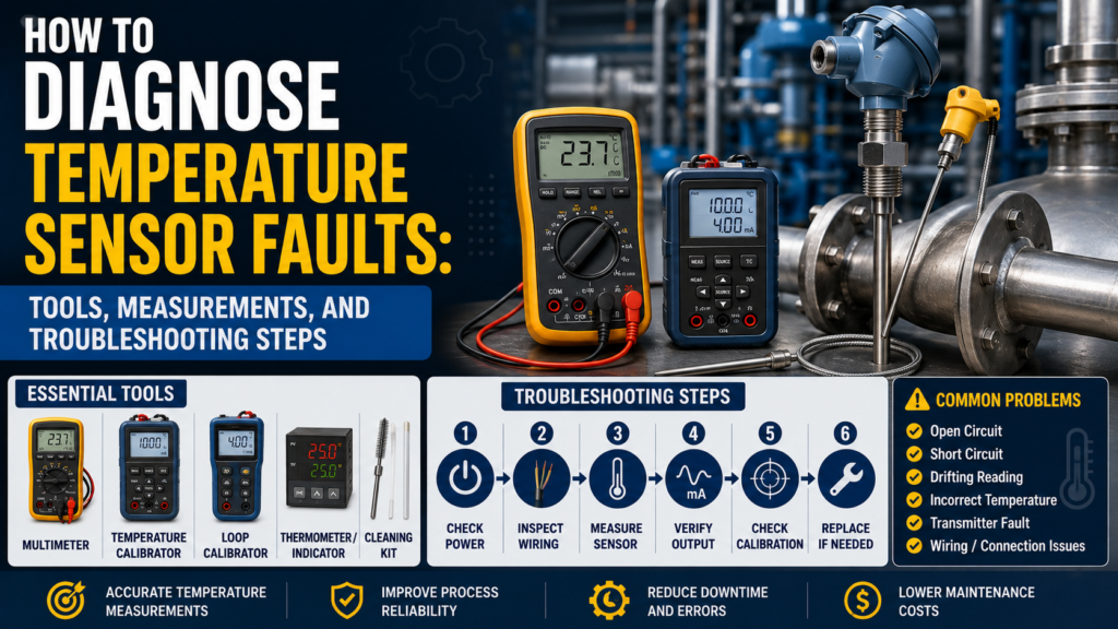
Tools Needed for Temperature Sensor Troubleshooting
1. Digital Multimeter
A multimeter is the first tool to use.
Use it to check:
24V DC power supply
Pt100 resistance
Pt1000 resistance
Thermocouple millivolts
Cable continuity
Short circuits
Loose wiring
4–20 mA signal
0–10V signal
Relay output
Grounding problems
For basic faults, a multimeter is usually enough.
2. Temperature Calibrator
A temperature calibrator is one of the best tools for temperature sensor troubleshooting.
It can simulate:
Pt100
Pt1000
Thermocouple Type K
Thermocouple Type J
Thermocouple Type T
Other RTD and thermocouple types
It can also measure sensor signals.
Use it to prove whether the transmitter or PLC input is reading correctly.
3. Loop Calibrator / Process Meter
A loop calibrator is useful for 4–20 mA temperature transmitters.
Use it to:
Measure transmitter output current
Simulate 4–20 mA into PLC input
Check PLC scaling
Check HMI scaling
Check alarm values
Prove whether the fault is transmitter-side or PLC-side
If the transmitter display is correct but the PLC value is wrong, use a loop calibrator.
4. Reference Thermometer
Use a reference thermometer to compare real process temperature.
This can be:
Digital thermometer
Infrared thermometer
Temperature probe
Calibrated handheld meter
Reference RTD probe
A reference thermometer helps answer a simple question:
Is the process actually at the temperature the sensor says?
5. Dry Block Calibrator or Temperature Bath
For more accurate testing, use:
Dry block calibrator
Liquid temperature bath
Ice bath
Boiling water check, if suitable
Calibration oven
These tools let you test the sensor at known temperatures.
For example:
0°C ice bath
50°C dry block
100°C water bath
150°C dry block
This is useful for calibration and accuracy checks.
6. Insulation Tester
Use carefully.
An insulation tester can help find:
Moisture inside the sensor
Cable insulation damage
Short to sensor body
Short to shield
Water inside connector
Thermowell leakage problems
But do not use it on connected transmitter electronics or PLC input modules.
Disconnect the sensor first and follow the sensor manual.
7. PLC Software
Use PLC software to check:
Raw analog input value
Scaled temperature value
Input module configuration
RTD type
Thermocouple type
4–20 mA scaling
Alarm logic
HMI tag scaling
Diagnostic bits
Open-circuit alarm
Short-circuit alarm
Many temperature faults are actually configuration or scaling problems.
8. Configuration Tool for Temperature Transmitters
Many temperature transmitters can be configured by software, HART, IO-Link, buttons, or display menu.
Check:
Sensor type
Pt100 / Pt1000 selection
2-wire / 3-wire / 4-wire setting
Thermocouple type
Cold junction compensation
Measuring range
Output range
Burnout behavior
Damping
Units
Offset correction
Calibration settings
Wrong transmitter configuration is a very common fault.
Step 1: Check the Local Display or Diagnostic Status
If the temperature transmitter has a display, start there.
Check:
Does it power on?
Does it show temperature?
Does it show an alarm?
Does it show sensor break?
Does it show short circuit?
Does it show overrange?
Does it show underrange?
Does it show the same value as the PLC?
If Display Is Correct but PLC Is Wrong
The problem is probably:
4–20 mA wiring
PLC analog input
PLC scaling
HMI scaling
Wrong units
Wrong analog range
Wrong channel
Communication mapping
If Display Is Wrong Too
The problem may be:
Sensor
Cable
Transmitter setting
Installation
Process condition
Power supply
Thermowell
Calibration
Step 2: Check Power Supply
Many temperature transmitters use 24V DC.
Measure voltage at the transmitter terminals.
Good 24V DC Reading
For many industrial transmitters:
20.4V DC to 28.8V DC is usually acceptable.
This is 24V ±20%.
Always check the device manual.
Bad Readings
0V
Wrong polarity
Voltage below allowed range
Unstable voltage
Voltage drops under load
High AC ripple
Loose 0V/common wire
Power supply overloaded
Measure the voltage while the transmitter is connected and operating.
A weak supply can look good without load but fail in real operation.
Step 3: Check Pt100 Resistance
A Pt100 sensor has:
100 Ω at 0°C
As temperature rises, resistance increases.
Approximate Pt100 values:
| Temperature | Pt100 Resistance |
|---|---|
| -50°C | about 80.3 Ω |
| 0°C | 100 Ω |
| 25°C | about 109.7 Ω |
| 50°C | about 119.4 Ω |
| 100°C | about 138.5 Ω |
| 150°C | about 157.3 Ω |
| 200°C | about 175.9 Ω |
To test a Pt100, disconnect it from the transmitter or PLC input if possible.
Measure resistance across the RTD element.
Good Pt100 Reading
Resistance is close to the expected value for the actual temperature
Reading is stable
Resistance increases when warmed
Resistance decreases when cooled
No open circuit
No short circuit
Bad Pt100 Reading
OL / open circuit
Near 0 Ω
Resistance far from expected value
Reading jumps when cable is moved
Short to shield
Short to sensor body
Different reading each time
Wrong resistance for actual temperature
Example:
If the process is around room temperature, a Pt100 should read around 108–110 Ω.
If it reads 0 Ω, there is probably a short.
If it reads OL, the sensor or cable is open.
Step 4: Check Pt1000 Resistance
A Pt1000 sensor has:
1000 Ω at 0°C
Approximate Pt1000 values:
| Temperature | Pt1000 Resistance |
|---|---|
| -50°C | about 803 Ω |
| 0°C | 1000 Ω |
| 25°C | about 1097 Ω |
| 50°C | about 1194 Ω |
| 100°C | about 1385 Ω |
| 150°C | about 1573 Ω |
| 200°C | about 1759 Ω |
Good Pt1000 Reading
Around 1097 Ω at 25°C
Stable resistance
Changes smoothly with temperature
No open circuit
No short circuit
Bad Pt1000 Reading
OL / open circuit
Near 0 Ω
Very different from expected value
Resistance jumps when cable is moved
Short to ground or shield
Moisture leakage causing unstable reading
Pt1000 sensors are more sensitive to insulation leakage than Pt100 in some installations, especially if moisture is present.
Step 5: Check RTD Wiring: 2-Wire, 3-Wire, or 4-Wire
RTD wiring method matters a lot.
2-Wire RTD
2-wire is simple, but cable resistance adds measurement error.
Good
Short cable
Stable terminals
Cable resistance known or compensated
Acceptable accuracy for the application
Bad
Long cable
High cable resistance
Loose terminals
Temperature reads too high
Offset changes when cable temperature changes
A 2-wire Pt100 can easily read too high because the transmitter measures both sensor resistance and wire resistance.
3-Wire RTD
3-wire is common in industry.
It compensates most lead wire resistance, but the wires should have equal resistance.
Good
Three wires connected correctly
Lead wires same size and length
Input module set to 3-wire
Temperature reading stable
Bad
One wire broken
Wrong terminal connection
Unequal wire resistance
Input set to 2-wire or 4-wire by mistake
Loose terminal
Reading offset or unstable
4-Wire RTD
4-wire is the most accurate.
It removes most effect of lead resistance.
Good
Four wires connected correctly
Input module set to 4-wire
Stable reading
Good for precision measurement
Bad
Wrong input configuration
One sense wire broken
Loose terminal
Input wired like 2-wire by mistake
Incorrect bridge links
If the wiring method is wrong, the sensor may be good but the reading will still be wrong.
Step 6: Check Thermocouple Signal
A thermocouple produces a small voltage in millivolts.
The voltage depends on:
Thermocouple type
Hot junction temperature
Cold junction temperature
Polarity
Cable material
For example, a Type K thermocouple produces approximately:
| Temperature Difference | Type K Approx. Output |
|---|---|
| 0°C | 0 mV |
| 100°C | about 4.1 mV |
| 200°C | about 8.1 mV |
| 500°C | about 20.6 mV |
| 1000°C | about 41.3 mV |
These are approximate values. Use a thermocouple table or calibrator for accurate testing.
Good Thermocouple Reading
Millivolt output changes when heated
Correct polarity
Stable signal
No open circuit
Correct thermocouple type configured
Correct extension cable used
Cold junction compensation working
Bad Thermocouple Reading
Open circuit
No mV change when heated
Polarity reversed
Wrong thermocouple type selected
Normal copper cable used incorrectly
Unstable mV signal
Signal jumps when cable moves
Moisture in junction box
Cold junction compensation fault
Thermocouple signals are very small, so wiring quality is important.
Step 7: Check Thermocouple Polarity
Thermocouples have polarity.
If polarity is reversed, the reading may go down when temperature goes up.
Good
Heating the thermocouple increases the displayed temperature
Cooling decreases the displayed temperature
Positive and negative wires are connected correctly
Bad
Heating makes the temperature go down
Temperature reads negative or strange value
Wires reversed at transmitter
Extension cable reversed
Connector polarity wrong
This is one of the easiest thermocouple faults to make.
Step 8: Check Thermocouple Type and Cable
A thermocouple input must be configured for the correct type.
Common types:
K
J
T
N
S
R
B
Good
Sensor type matches transmitter setting
Extension cable matches thermocouple type
Correct thermocouple connector used
No copper extension cable unless allowed and compensated correctly
Bad
Type K sensor configured as Type J
Type J sensor configured as Type K
Wrong compensating cable
Mixed thermocouple wires
Copper cable used in the wrong place
Cold junction error
Wrong temperature after cable extension
If a thermocouple was extended during maintenance and the wrong cable was used, the reading can become wrong.
Step 9: Check Cold Junction Compensation
Thermocouples measure temperature difference.
The transmitter must compensate for the temperature at the terminal connection.
This is called cold junction compensation.
Good
Cold junction temperature is close to real transmitter terminal temperature
Temperature reading is stable
Transmitter configured correctly
No large temperature gradient at terminal block
Bad
Cold junction sensor faulty
Transmitter mounted in hot cabinet
Terminal area heated by nearby device
Cold junction compensation disabled
External compensation configured wrong
Temperature changes when panel door opens
If the transmitter terminal temperature is wrong, the process temperature calculation will be wrong.
Step 10: Check 4–20 mA Temperature Transmitter Output
Many temperature sensors connect to a transmitter.
The transmitter converts the raw sensor signal into 4–20 mA.
Example range:
0°C = 4 mA
100°C = 20 mA
| Temperature | Expected Current |
|---|---|
| 0°C | 4 mA |
| 25°C | 8 mA |
| 50°C | 12 mA |
| 75°C | 16 mA |
| 100°C | 20 mA |
Another example:
-50°C = 4 mA
150°C = 20 mA
In this case:
50°C is halfway between -50°C and 150°C, so expected output is 12 mA.
Good 4–20 mA Reading
Current matches transmitter display and configured range
Around 4 mA at lower range value
Around 12 mA at 50% of range
Around 20 mA at upper range value
Signal changes smoothly with temperature
Bad 4–20 mA Reading
| Reading | Possible Problem |
|---|---|
| 0 mA | Broken loop, no power, wrong wiring |
| Below 3.6 mA | Fault alarm on many transmitters |
| 4 mA all the time | Lower range value, stuck output, sensor fault, wrong range |
| 20 mA all the time | Upper range value, overrange, saturated output |
| Above 21 mA | Fault alarm or overrange on many transmitters |
| Jumping current | Loose wire, noise, transmitter fault |
| Display correct but mA wrong | Output configuration problem |
| mA correct but PLC wrong | PLC scaling problem |
Alarm current depends on transmitter configuration.
Step 11: Check 0–10V Output
Some temperature transmitters output 0–10V.
Example:
0°C = 0V
100°C = 10V
| Temperature | Expected Voltage |
|---|---|
| 0°C | 0V |
| 25°C | 2.5V |
| 50°C | 5V |
| 75°C | 7.5V |
| 100°C | 10V |
Good Voltage Output
Voltage matches configured range
Stable signal
Smooth change with temperature
PLC value matches voltage
Bad Voltage Output
0V all the time
10V all the time
Voltage unstable
Voltage drops when connected to PLC
Correct voltage but wrong PLC value
Voltage noise from nearby power cables
Voltage signals are usually more sensitive to long cable runs and noise than 4–20 mA.
Step 12: Simulate the PLC Input
If the transmitter output is correct but the PLC value is wrong, test the PLC input.
Use a loop calibrator or signal simulator.
For 4–20 mA:
| Simulated Current | PLC Should Show |
|---|---|
| 4 mA | Lower range value |
| 8 mA | 25% of range |
| 12 mA | 50% of range |
| 16 mA | 75% of range |
| 20 mA | Upper range value |
For 0–10V:
| Simulated Voltage | PLC Should Show |
|---|---|
| 0V | Lower range value |
| 5V | 50% of range |
| 10V | Upper range value |
If the PLC does not show the correct value, the problem is likely:
PLC scaling
Analog input configuration
Wrong signal type
Wrong input channel
Wrong HMI tag
Wrong engineering range
Wrong units
Step 13: Check PLC Scaling and Units
Temperature scaling mistakes are common.
Check:
Transmitter range
PLC input range
HMI range
°C vs °F
4–20 mA vs 0–20 mA
0–10V vs 2–10V
Raw input value
Decimal point
Offset
Linear scaling block
Wrong channel
Wrong tag
Example
Transmitter range:
0–100°C = 4–20 mA
Measured current:
12 mA
Correct temperature:
50°C
If the PLC shows 75°C, the sensor may not be bad. The scaling may be wrong.
Step 14: Check Sensor Installation
A temperature sensor can be electrically correct but installed badly.
Check:
Is the probe inserted far enough?
Is the tip in the actual process flow?
Is the sensor installed in a dead leg?
Is the thermowell too thick?
Is the probe touching the bottom of the thermowell?
Is there thermal paste if required?
Is the sensor loose?
Is it measuring pipe wall temperature instead of liquid temperature?
Is the medium mixed properly?
Is there air around the sensor tip?
Good Installation
Sensor tip is in representative process area
Correct insertion depth
Good thermal contact
Correct thermowell length
No dead zone
Process is mixed
Probe is tight and secure
Bad Installation
Sensor too short
Tip near pipe wall
Sensor in stagnant area
Poor thermowell contact
Air pocket around probe
Probe not reaching thermowell bottom
Thermowell coated or insulated by buildup
Sensor mounted near heater but not in process flow
Bad installation can cause slow response or wrong reading.
Step 15: Check Thermowell Problems
A thermowell protects the sensor, but it can also create faults.
Common problems:
Sensor not fully inserted
Bad thermal contact
Thermowell filled with water or oil unintentionally
Thermowell wall too thick
Buildup on thermowell
Wrong insertion depth
Thermowell installed in wrong location
Sensor spring loading damaged
Air gap between sensor and thermowell
Good
Sensor tip reaches thermowell bottom
Spring loading works
Good thermal contact
Thermowell is clean
Response time acceptable
Reading matches reference
Bad
Slow temperature response
Reading lower or higher than process
Large delay after temperature change
Sensor loose inside thermowell
Thermowell coated with product
Sensor not long enough
If the sensor reads correctly in a calibrator but wrong in the process, check the thermowell and installation.
Step 16: Check Cable and Connector
Cables and connectors are common fault points.
Check:
Loose terminals
Corrosion
Moisture
Broken shield
Damaged insulation
Wrong cable type
Cable pulled tight
Cable routed near motor cables
Bad gland
Wrong thermocouple extension cable
Broken conductor
Good
Cable intact
Terminals tight
Connector dry
No corrosion
Stable reading when cable is moved
Correct cable type used
Bad
Temperature jumps when cable is touched
Moisture inside connector
Green corrosion
Open circuit when cable bends
Short to shield
Thermocouple extension cable wrong
Loose terminal block
Move the cable gently while watching the temperature value.
If the reading jumps, suspect cable or connector damage.
Step 17: Check Insulation Resistance
Insulation faults can cause drift and unstable readings.
Disconnect the sensor from electronics before testing.
General Practical Values
| Insulation Resistance | Meaning |
|---|---|
| >100 MΩ | Very good |
| 20–100 MΩ | Usually acceptable, check manual |
| 1–20 MΩ | Suspicious |
| <1 MΩ | Usually bad |
Measure between:
Sensor wires and sensor body
Sensor wires and shield
Sensor wires and ground
Cable cores and shield
Bad Causes
Moisture inside probe
Damaged cable
Water in connector
Chemical ingress
Cracked sensor body
Condensation in junction box
Damaged insulation at high temperature
Low insulation can create temperature drift, wrong readings, or random faults.
Step 18: Check Electrical Noise and Grounding
Temperature signals can be affected by noise.
Thermocouples are especially sensitive because their signal is very small.
Common noise sources:
VFD motor cables
Servo drives
Large contactors
Solenoid valves
Heaters switching
Welding equipment
Poor shielding
Poor grounding
Long sensor cables
Ground loops
Good
Sensor cable separated from power cables
Shield connected according to manual
Panel grounding is good
No spikes on analog signal
Temperature stable when motors start
No large ground voltage difference
Bad
Temperature jumps when VFD starts
Reading changes with motor speed
Thermocouple signal noisy
Cable routed beside heater power cable
Shield disconnected
Ground difference above about 1V AC or DC
Temperature value spikes when contactors switch
Measure voltage between sensor body, machine frame, and panel PE.
It should be close to 0V.
More than about 1V AC or DC between grounding points is suspicious.
Step 19: Check Response Time
Sometimes the temperature is correct, but the sensor reacts too slowly.
Causes of slow response:
Large thermowell
Thick probe
Low flow
Poor contact inside thermowell
Sensor installed in stagnant area
Buildup on thermowell
Damping/filter setting too high
PLC averaging too strong
Good
Temperature follows process changes quickly enough
Response time matches application need
No excessive delay
Control loop stable
Bad
Heater overshoots because sensor reacts late
Temperature display changes very slowly
Sensor reads old temperature after process changes
Temperature alarms activate too late
PLC filter/damping too high
If control is unstable, check sensor response time and installation.
Step 20: Check Transmitter Configuration
Temperature transmitters must be configured correctly.
Check:
Input type: Pt100, Pt1000, Type K, Type J, etc.
RTD wiring: 2-wire, 3-wire, 4-wire
Temperature range
Output range
Units
Burnout behavior
Sensor break detection
Damping
Offset
Cold junction compensation
Linearization curve
HART or digital mapping
Good
Transmitter input matches actual sensor
Range matches PLC scaling
Units match HMI
No unnecessary offset
Diagnostics are clear
Output current matches display
Bad
Pt100 selected but Pt1000 installed
Type K selected but Type J installed
3-wire selected but 2-wire connected
Output range changed after maintenance
Burnout set to wrong direction
Offset added by mistake
PLC range does not match transmitter range
Wrong configuration can make a good sensor look bad.
Troubleshooting by Symptom
1. No Temperature Reading
Possible causes:
No power
Broken sensor
Open circuit
Wrong wiring
Bad transmitter
PLC input fault
Sensor not connected
Checks:
Measure power supply
Check sensor resistance or thermocouple mV
Check cable continuity
Check transmitter diagnostics
Check PLC input
2. Temperature Reads Too High
Possible causes:
2-wire RTD cable resistance
Wrong sensor type
Wrong scaling
Thermocouple polarity or type issue
Sensor near heater
Poor installation
Transmitter offset
PLC scaling error
Self-heating
Checks:
Measure RTD resistance
Check transmitter configuration
Compare with reference thermometer
Check installation position
Check PLC scaling
3. Temperature Reads Too Low
Possible causes:
Sensor not inserted far enough
Bad thermowell contact
Wrong sensor type
Wrong thermocouple type
Wrong transmitter range
PLC scaling error
Cold junction problem
Sensor in dead zone
Checks:
Check insertion depth
Check thermowell fit
Compare with reference
Check transmitter and PLC settings
Test sensor in dry block
4. Temperature Jumps Randomly
Possible causes:
Loose terminal
Broken cable
Moisture
Electrical noise
Thermocouple signal interference
Bad shielding
Bad grounding
Failing sensor element
Checks:
Move cable gently
Inspect connector
Check insulation resistance
Check shield
Watch signal when motors start
Use oscilloscope if needed
5. Temperature Drifts Slowly
Possible causes:
Moisture ingress
Insulation fault
Sensor aging
Thermowell buildup
Poor contact
Transmitter drift
Process change
Bad calibration
Checks:
Check insulation resistance
Compare with reference thermometer
Test in calibrator
Inspect thermowell
Check calibration history
6. PLC Value Wrong but Transmitter Display Correct
Possible causes:
Wrong PLC scaling
Wrong analog input type
Wrong HMI tag
Wrong units
Wrong 4–20 mA range
Wrong communication mapping
Checks:
Measure 4–20 mA
Simulate PLC input
Check PLC raw value
Check HMI scaling
Check °C/°F setting
7. Thermocouple Reading Goes Down When Heated
Possible causes:
Polarity reversed
Extension cable reversed
Wrong terminal connection
Checks:
Check thermocouple polarity
Heat sensor tip and watch direction
Check terminal markings
Check connector polarity
8. RTD Shows Open Circuit
Possible causes:
Broken element
Broken cable
Loose terminal
Wrong wiring
Connector fault
Checks:
Measure resistance at sensor head
Measure resistance at transmitter end
Check each wire continuity
Inspect terminals
Quick Measurement Table
| Test | Good Measurement | Bad Measurement |
|---|---|---|
| 24V DC supply | Usually 20.4–28.8V DC | Missing, low, unstable, reversed |
| Pt100 at 0°C | 100 Ω | OL, near 0 Ω, far off |
| Pt100 at 25°C | About 109.7 Ω | Far from expected |
| Pt100 at 100°C | About 138.5 Ω | Far from expected |
| Pt1000 at 0°C | 1000 Ω | OL, near 0 Ω, far off |
| Pt1000 at 25°C | About 1097 Ω | Far from expected |
| Pt1000 at 100°C | About 1385 Ω | Far from expected |
| Type K at 100°C difference | About 4.1 mV | No change, unstable, reversed |
| 4–20 mA at 0% | Around 4 mA | 0 mA, alarm current |
| 4–20 mA at 50% | Around 12 mA | Wrong current for range |
| 4–20 mA at 100% | Around 20 mA | Saturated or wrong range |
| 0–10V at 50% | Around 5V | Wrong voltage or unstable |
| Insulation resistance | >100 MΩ very good | <1 MΩ usually bad |
| Ground difference | Close to 0V | >1V suspicious |
| PLC simulation | Correct scaled value | Scaling/input problem |
What Readings Are Usually Good?
These are general practical values:
24V DC supply around 20.4–28.8V DC
Pt100 around 109.7 Ω at 25°C
Pt1000 around 1097 Ω at 25°C
Pt100 resistance increases smoothly when heated
Pt1000 resistance increases smoothly when heated
Thermocouple millivolt signal increases when heated
Type K thermocouple around 4.1 mV at 100°C temperature difference
4 mA at lower transmitter range
12 mA at middle of transmitter range
20 mA at upper transmitter range
0–10V output gives 5V at 50% range
Insulation resistance above 100 MΩ is very good
PLC value matches measured 4–20 mA or 0–10V signal
Reference thermometer is close to sensor value
Temperature changes smoothly, not randomly
What Readings Are Usually Bad?
These readings usually indicate a fault:
0V power supply
Wrong polarity
24V supply below allowed range
Pt100 open circuit
Pt100 near 0 Ω
Pt100 far from expected value
Pt1000 open circuit
Pt1000 near 0 Ω
RTD resistance jumps when cable moves
Thermocouple mV does not change when heated
Thermocouple polarity reversed
Thermocouple signal unstable
4–20 mA output at 0 mA
Output below 3.6 mA or above 21 mA without known reason
4 mA all the time while temperature changes
20 mA all the time during normal temperature
0–10V output stuck at 0V or 10V
Insulation resistance below 1 MΩ
Temperature jumps when motor starts
PLC value does not match transmitter display
Sensor reads correctly in calibrator but wrong in process
Practical Diagnostic Order
When diagnosing a temperature sensor, I would follow this order:
- Identify sensor type: Pt100, Pt1000, thermocouple, or transmitter.
- Check local display and diagnostic messages.
- Check real process temperature with a reference thermometer.
- Measure power supply voltage.
- For RTD sensors, measure resistance.
- For thermocouples, check mV signal and polarity.
- Check cable continuity and terminals.
- Check transmitter configuration.
- Measure 4–20 mA or 0–10V output.
- Compare transmitter display with PLC value.
- Simulate PLC input to test scaling.
- Check PLC units and range.
- Check sensor insertion depth and thermowell contact.
- Check cable, connector, moisture, and insulation resistance.
- Check grounding, shielding, and noise.
- Test sensor in a dry block or temperature bath if accuracy is important.
- Review calibration history and offset settings.
This method helps avoid replacing a good sensor when the real issue is wiring, scaling, installation, or configuration.
Final Thoughts
Temperature sensor troubleshooting is not only about checking the sensor element.
A Pt100, Pt1000, or thermocouple can be electrically healthy but still show a wrong value because of poor installation, wrong wiring, bad transmitter settings, wrong PLC scaling, or poor thermal contact.
The most useful tools are:
Digital multimeter
Temperature calibrator
Loop calibrator
Reference thermometer
Dry block calibrator
PLC software
Transmitter configuration tool
Insulation tester
Oscilloscope
The most important measurements are:
Pt100 resistance
Pt1000 resistance
Thermocouple millivolts
24V DC supply
4–20 mA output
0–10V output
Insulation resistance
PLC raw value
Reference temperature
The key rule is simple:
If the transmitter display is correct but the PLC value is wrong, check output wiring and PLC scaling.
If the sensor reads correctly in a calibrator but wrong in the process, check installation and thermowell contact.
If the raw sensor signal is wrong, check the sensor, cable, terminals, moisture, and sensor type.