At some point every control scheme leaves the panel and reaches out to devices in the field — sensors, motors, valves, operator stations scattered around the machine. Terminal blocks are where this transition happens, and on a drawing they are the marked meeting points between panel wiring and field wiring. Reading them is what connects the abstract drawing to the physical plant.

What a terminal block is
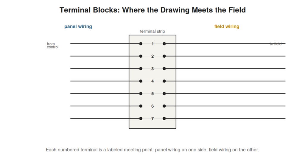
A terminal block is a strip of numbered terminals, each a connection point where a panel wire meets a field wire. On the drawing, terminals appear as numbered points, and the number is the key: terminal 7 on the drawing is terminal 7 on the physical strip, so a connection shown at a numbered terminal can be found at that exact terminal in the panel. Terminal blocks organize the many wires crossing between panel and field into an orderly, labeled set of junctions, and reading them means using the terminal numbers to locate physical connections. When a drawing shows a field device connected through certain terminals, those numbers lead you straight to the physical terminals where you can measure or verify the connection.
Panel side and field side
A terminal block has two sides, and reading the drawing means distinguishing them. On the panel side are the wires internal to the control panel — connecting to the control logic, the PLC, the power circuits. On the field side are the wires running out to the devices in the plant — the sensors, motors, and stations. The terminal is the junction between them, and reading the drawing tells you which internal circuit connects, through which terminal, to which field device. This is invaluable in troubleshooting a field device, because the terminal block is where you can conveniently measure: the drawing tells you which terminal carries the signal to or from a suspect field device, and you can test at that terminal to determine whether the fault is on the panel side or the field side of it. The terminal block, read from the drawing, is both a map to physical connections and a natural dividing point for isolating field faults.
Following a signal into the field
Reading field wiring means following a signal from the control logic, through the terminal block, out to the field device and back. A sensor in the field, for instance, connects through field wiring to certain terminals, from which panel wiring carries its signal to the input of the control logic or PLC. Reading this path on the drawing — from the field device, through the numbered terminals, to the internal circuit — lets you trace the whole connection and, crucially, locate each part of it physically. When that sensor’s signal is suspect, the drawing’s path tells you where to check: at the device, at the field-side terminal, at the panel-side terminal, at the input. Following signals through terminal blocks into the field is what connects the reading of a drawing to the physical work of measuring and verifying in the plant, completing the link from the abstract schematic to the concrete installation.
The terminal block as a troubleshooting boundary
The terminal block’s greatest value in troubleshooting is as a natural boundary where you can divide a fault between the panel and the field. Because every wire crossing between panel and field passes through a numbered terminal, the terminal is an accessible test point that separates the two worlds. Suppose a field sensor’s signal is not reaching the control logic. The drawing shows the sensor connects through a specific terminal. Measuring at that terminal splits the fault: if the correct signal is present at the field side of the terminal, the sensor and field wiring are good and the fault is on the panel side; if the signal is absent at the field side, the fault is in the sensor or field wiring. This divide-and-conquer, enabled by reading the terminal numbers from the drawing, is one of the most efficient troubleshooting techniques, because a single measurement at the terminal eliminates half the possible fault locations. Reading the drawing to find which terminal carries a suspect signal turns the terminal block into a diagnostic boundary that dramatically narrows the search.
Reading exercise: following a field device to the panel
Practice reading field wiring by picking a field device on a drawing and following its connection all the way into the panel — through the field wiring, to the numbered terminals, through the panel wiring, to the control logic or PLC input. Name each step: the device, the field wires, the specific terminals (by number), the panel wires, the destination. This traces the full path from field to control and, crucially, identifies the physical locations — especially the terminal numbers — where you could measure along the path. Doing this for various field devices builds the skill of connecting the drawing to the physical installation via terminal numbers, which is what lets you locate and test any field connection. The exercise turns the abstract drawing into a set of physical locations you can find and probe, and it particularly builds fluency with terminal numbers as the link between drawing and panel. Practicing it prepares you to troubleshoot field faults efficiently, because when a field device is suspect, you will already be practiced at following its connection to the terminals where you can divide the fault between field and panel.
Reading terminal designations and cable markings
Terminal blocks and field wiring carry designations and markings that, read correctly, make the physical wiring navigable, and understanding the conventions helps. Terminals are numbered or labeled in a systematic scheme, and cables and wires carry markings identifying them — wire numbers, cable numbers, sometimes color codes. Reading these designations on the drawing and matching them to the physical markings is what lets you find a specific terminal or wire among many. The conventions vary — different sites and standards number and label differently — but the principle is constant: the drawing’s designations correspond to physical markings, and reading the correspondence locates the physical item. Understanding the particular scheme in use (from the drawing’s notes or legend) lets you read the designations correctly and find what they refer to. This attention to terminal designations and cable markings is what makes the terminal block and field wiring genuinely navigable, turning the drawing’s labels into a means of finding physical connections in a panel or field that might otherwise be an unnavigable mass of wires. Reading the markings is reading the map that leads to the physical wire.
Reading for wiring errors and loose connections
Terminal blocks are common sites of a particular class of faults — loose connections and wiring errors — and reading the drawing to check the wiring against it is how these are found. A loose terminal connection can cause intermittent faults, high resistance, or complete opens, and because terminals are mechanical connection points subject to vibration and thermal cycling, they are prone to loosening over time. Reading the drawing to know which terminals carry a suspect circuit lets you check those specific terminals for tightness and correct connection. Wiring errors — a wire on the wrong terminal — are found by comparing the actual wiring to the drawing’s specification of which wire belongs on which terminal. Reading the drawing provides the correct configuration against which to check the actual terminals, revealing both loose connections (at the right terminals) and errors (wires not matching the drawing). Because terminal blocks concentrate many connections in an accessible place, they are both a common fault site and a convenient place to check, and reading the drawing to know what should be at each terminal turns that convenience into effective troubleshooting of the connection faults that terminals are prone to.
Case: the field fault isolated at the terminal
The terminal block’s role as a diagnostic boundary is shown in this case. A field device was not working, and the fault could have been in the device, the field wiring, the terminal, or the panel wiring. Reading the drawing, the technician found which terminal the device connected through and measured there. The measurement at the terminal split the fault: the correct signal was present on the panel side of the terminal but absent on the field side, isolating the fault to the field side — the device or the field wiring, not the panel. This single measurement at the terminal eliminated the panel side, focusing the search on the field wiring and device, where the fault was found. Reading the drawing to identify the terminal, then measuring there to split the fault between panel and field, is the efficient technique this case demonstrates. The terminal block, read from the drawing, provided the accessible boundary point where one measurement divided the fault space in half, directing the search to the correct side. This case shows the practical power of reading terminal connections: the terminal is where you can conveniently split a field fault between panel and field, and reading the drawing to find the right terminal makes that split possible, turning a fault that could be in four places into one located on the correct side of the terminal by a single measurement.
The terminal block as the reader’s ally
The terminal block deserves appreciation as the reader’s ally in connecting the drawing to the physical world, because it provides the accessible, labeled points where the abstract drawing meets the concrete wiring you can touch and measure. Where much of a circuit is buried in wiring harnesses and inside devices, the terminal block brings connections out to an accessible, numbered strip where they can be found and tested. Reading the drawing to identify terminal numbers gives you access to the circuit at these convenient points — for measuring, for splitting faults, for verifying connections. The terminal block is thus the reader’s friend, the place where reading the drawing translates most directly into physical action, because the terminal numbers on the drawing lead straight to accessible physical points. Appreciating and using the terminal block this way — as the accessible interface between drawing and installation — makes reading the drawing practically powerful, because it is at the terminals that the reading most easily becomes measurement and verification. The terminal block, read from the drawing via its numbers, is where the abstract understanding from reading meets the concrete work of the panel, and it is the reader’s ally in making the drawing’s information physically actionable, which is why reading terminal connections is so practically valuable.