Multimeter: Power Checks First
A multimeter is excellent for supply voltage, return drop, continuity under isolation, and some frequency measurements. It is not a complete substitute for an oscilloscope because it averages fast digital signals.
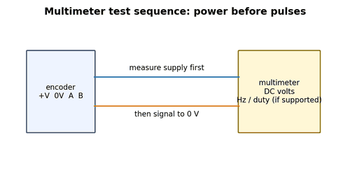
What to Check
- Verify meter category/rating for the circuit.
- Measure encoder supply at the encoder.
- Measure supply while the fault occurs.
Diagnostic Sequence
- Check +V to 0 V first.
- Then check signal DC level while rotating slowly.
- Use Hz mode only if the meter frequency range and input levels are suitable.
Common Mistakes
- Interpreting a 12 V average on a 24 V square wave as a 12 V signal.
- Using continuity on an energized circuit.
- Forgetting that meter leads can miss millisecond dropouts.
Field Rule: Use the meter to prove power and gross signal behavior; use a scope for signal integrity.
Multimeter: Frequency Mode
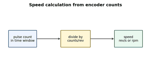
Many meters can display frequency, making them useful for verifying whether pulse rate tracks shaft speed. Accuracy depends on input amplitude, duty cycle, and meter bandwidth.
What to Check
- Check meter frequency range.
- Measure one channel to the correct reference.
- Compare measured Hz with calculated expectation.
Diagnostic Sequence
- Jog at a known rpm.
- Calculate expected frequency from PPR.
- If frequency is correct but PLC speed is wrong, investigate scaling/input configuration.
Common Mistakes
- Expecting the meter to decode quadrature direction.
- Measuring a differential pair incorrectly.
- Using Hz mode on amplitude outside the meter specification.
Field Rule: Frequency mode is a quick plausibility test, not a full encoder test.
Oscilloscope: Two-Channel A/B Test
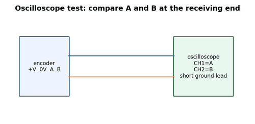
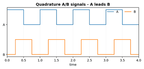
A two-channel oscilloscope can display A and B at the same time, revealing amplitude, phase, noise, missing edges, and duty cycle. Measure at the controller end when diagnosing what the controller actually receives.
What to Check
- Use suitable probes and safe grounding.
- Set timebase to show several cycles.
- Trigger on one channel and compare the other.
Diagnostic Sequence
- Capture slow jog first.
- Then increase to production speed.
- Look for edge distortion, phase collapse, spikes, and dropouts.
Common Mistakes
- Using long ground leads near a noisy drive.
- Measuring both channels but with different reference points.
- Declaring success from a single short capture.
Field Rule: A/B on one screen is the fastest way to separate direction, phase, and integrity problems.
Oscilloscope: Triggering on Intermittent Faults
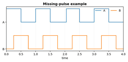
Rare encoder dropouts require trigger strategies. A scope with single-shot, pulse-width, runt, or dropout triggering can capture events that a normal rolling display misses.
What to Check
- Know the expected amplitude and pulse width.
- Select a trigger condition that represents the fault.
- Use enough memory depth for context before and after the event.
Diagnostic Sequence
- Trigger on an abnormally narrow pulse or low amplitude.
- Correlate the capture with drive fault time.
- Save reference captures from a healthy channel.
Common Mistakes
- Watching the screen continuously and hoping to see a rare glitch.
- Using too short a time window.
- Triggering on noise that is unrelated to the receiver threshold.
Field Rule: For intermittent faults, configure the instrument to wait for the abnormal event.
Logic Analyzer and Counter Tools
Logic analyzers and dedicated counters can record long sequences of digital transitions. They are useful for low-voltage logic and protocol analysis, but input voltage limits and grounding must be respected in industrial environments.
What to Check
- Verify voltage compatibility and isolation.
- Use a proper interface for 24 V or differential signals.
- Capture A/B/Z or serial clock/data together.
Diagnostic Sequence
- Compare edge count over a complete machine cycle.
- Decode direction transitions.
- Use protocol decoding only after proving clean electrical levels.
Common Mistakes
- Connecting 24 V directly to a 5 V logic analyzer.
- Assuming decoded data is trustworthy when the waveform is marginal.
- Using hobby equipment in unsafe energized environments.
Field Rule: Protocol decoding starts after electrical compatibility is proven.
Continuity and Resistance Testing
With power isolated, resistance checks can identify open conductors, shorted pairs, and poor contacts. They cannot prove high-frequency signal quality and may miss intermittent faults that appear only while flexing.
What to Check
- Lock out and verify de-energized state.
- Disconnect electronics if resistance testing could backfeed them.
- Measure each conductor end to end and conductor-to-conductor insulation as appropriate.
Diagnostic Sequence
- Flex moving sections during the test.
- Compare shield continuity.
- Check for unexpected resistance changes at connectors.
Common Mistakes
- Megger-testing delicate electronics while connected.
- Accepting one static continuity reading as proof of a flex cable.
- Ignoring leakage paths from coolant or contamination.
Field Rule: Resistance testing is valuable when used within its limits and with electronics protected.
Breakout Cables and Test Adapters
A proper breakout adapter lets you access encoder signals without damaging connector contacts. It also preserves normal loading while giving the scope or meter a stable point to connect.
What to Check
- Use pin-for-pin adapters rated for the signal and environment.
- Label test points clearly.
- Keep differential pair geometry intact.
Diagnostic Sequence
- Compare input and output through the adapter before relying on it.
- Use short probe leads.
- Remove the adapter after troubleshooting unless designed for permanent use.
Common Mistakes
- Back-probing with oversized pins.
- Introducing a long unshielded test lead that creates the fault.
- Using an adapter with incorrect pin numbering.
Field Rule: Good test access improves diagnosis and prevents connector damage.
Measuring at Encoder vs. Receiver
The same signal can be clean at the encoder and corrupted after 30 metres of cable. Always decide where to measure based on the question you are asking.
What to Check
- At encoder: does the device generate a valid signal?
- At receiver: what does the controller actually see?
- Across the cable: where does degradation appear?
Diagnostic Sequence
- Start at receiver because it represents system performance.
- Move upstream only if the received signal is bad.
- Compare loaded conditions at both points.
Common Mistakes
- Testing only at the encoder and overlooking cable faults.
- Testing only at the PLC and replacing a healthy encoder.
- Changing cable and encoder at the same time.
Field Rule: Troubleshooting gets faster when each measurement answers a specific location question.
Interpreting an Average DC Reading
A square wave that switches between 0 and 24 V at 50% duty cycle may read near 12 V on a DC meter. That does not mean the encoder is producing an analog 12 V signal. The reading is an average.
What to Check
- Rotate slowly and see whether the meter alternates between stable high/low at very low pulse rate.
- Use frequency mode if available.
- Use a scope for waveform shape.
Diagnostic Sequence
- If the meter shows an intermediate value during normal speed, do not conclude that logic level is wrong.
- Stop the shaft at different positions if possible and check stable states.
- Compare with input LED cautiously because LEDs may also average.
Common Mistakes
- Replacing an encoder because the meter reads “half voltage.”
- Trying to tune a digital encoder like an analog sensor.
- Ignoring duty cycle and frequency.
Field Rule: A meter can hide the switching nature of a digital pulse train.
Measurement Safety Around Drives
Drive cabinets can contain hazardous voltages while encoder circuits may be low voltage. Probe placement, reference grounding, and instrument rating still matter because grounds can connect unexpectedly through the instrument.
What to Check
- Understand whether the scope is earth-referenced or isolated.
- Use differential probes where required.
- Follow energized-work rules and arc-flash requirements.
Diagnostic Sequence
- Prefer measuring low-voltage encoder terminals when they are safely accessible.
- Keep probes mechanically secure.
- Do not connect an oscilloscope ground clip to an unknown potential.
Common Mistakes
- Assuming a 5 V signal is automatically safe to probe anywhere.
- Allowing test leads to contact power terminals.
- Floating a grounded bench scope by defeating protective earth.
Field Rule: Never defeat instrument protective earth to make a measurement work.