A motor does not always fail loudly.
Sometimes it fails slowly. Quietly. A little too much current, a little too much heat, a little too long under load — and then one day the winding insulation gives up. After that, the repair is no longer a small adjustment. It becomes a burned motor, production stop, rewinding cost, and someone asking why nobody noticed earlier.
That is exactly the kind of problem a thermal overload relay is designed to prevent.
Thermal overload relays are used to protect electric motors from overcurrent conditions that last long enough to cause overheating. They do not usually protect against short circuits. That job belongs to fuses, circuit breakers, or motor protection breakers. A thermal overload relay is more about overload protection: too much current for too long.
Simple idea. Very important device.
What Is a Thermal Overload Relay?
A thermal overload relay is a motor protection device that monitors the current drawn by an electric motor. If the motor current becomes higher than the set value for a certain time, the overload relay trips and stops the motor indirectly.
The word “relay” can be slightly confusing here.
A thermal overload relay is not a relay in the same sense as a normal control relay. It is not mainly used to switch power directly. It is better to think of it as a current-sensing protection device.
It detects excessive motor current, reacts to the heating effect of that current, and then opens a control circuit. This control circuit usually belongs to a contactor. When the contactor coil loses power, the contactor opens, and the motor stops.
So, the overload relay does not normally interrupt the main motor current by itself.
The contactor does the switching.
The overload relay does the detecting.
Together, they form a very common motor starter arrangement.
Thermal Overload Relay and Contactor
In many motor control circuits, the contactor and overload relay work as a pair.
The contactor is the actual switching device. It connects and disconnects the motor from the power supply. The thermal overload relay is mounted electrically and mechanically with the contactor, usually below it in a motor starter assembly.
During normal operation, motor current flows through the overload relay before going to the motor. The relay continuously “watches” this current. If the current stays within the allowed range, nothing happens. The motor keeps running.
But when the motor draws too much current for too long, the overload relay trips. Its normally closed auxiliary contact opens the contactor coil circuit. The contactor drops out. The motor is disconnected.
That is the basic protection sequence.
Motor overload → overload relay trips → contactor coil de-energizes → contactor opens → motor stops.
Not dramatic, but effective.
Why Motors Need Overload Protection
Every electric motor has a rated or nominal current. This value is usually written on the motor nameplate and is often marked as In, FLA, or rated current.
This rated current is the current the motor should draw under normal operating conditions at its rated voltage, frequency, and load.
If the real motor current becomes higher than the rated current, the motor starts heating more than it should. A short current peak during starting is normal, of course. Motors can draw several times their rated current during startup. But if high current continues after starting, something is wrong.
Possible causes include:
- Mechanical overload
- Jammed conveyor
- Blocked pump
- Worn bearings
- Phase loss
- Phase imbalance
- Incorrect motor sizing
- Low supply voltage
- Too frequent starts
- Poor ventilation
- Damaged motor winding
If this continues, the motor insulation can be damaged by heat. And once insulation is damaged, the motor can fail completely.
A thermal overload relay helps prevent that by disconnecting the motor before the heating becomes destructive.
Basic Working Principle
The working principle of a thermal overload relay is based on heat.
More current creates more heat. More heat causes a mechanical movement inside the relay. This movement trips the auxiliary contacts.
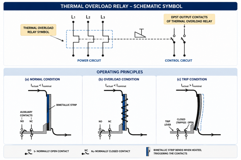
Traditional thermal overload relays use bimetallic strips. A bimetallic strip is made from two different metals bonded together. These metals expand at different rates when heated.
Because one metal expands more than the other, the strip bends.
That bending movement is used to operate a trip mechanism.
In normal operation, the current is within the correct range, so the bimetallic strip does not bend enough to trip the relay. The auxiliary contacts remain in their normal position.
During overload, current increases. The bimetal heats up. It bends farther. Eventually, it pushes the trip mechanism and changes the state of the auxiliary contacts.
A small piece of metal bending from heat. That’s the whole trick.
Old-school, but clever.
Direct and Indirect Heating
A thermal overload relay can heat its bimetallic strips in two main ways: direct heating or indirect heating.
In direct heating, the motor current flows directly through the bimetallic strip. As current passes through it, the strip heats up and bends.
In indirect heating, the current flows through a heating element or winding placed near the bimetallic strip. The heat from this element warms the strip, causing it to bend.
Both methods are based on the same idea: motor current creates heat, and heat creates movement.
This makes the relay naturally time-dependent. A small overload may take longer to trip. A larger overload trips faster. That is useful because motors can tolerate short current peaks but cannot tolerate long overloads.
Auxiliary Contacts: NC and NO
Most thermal overload relays have auxiliary contacts used in the control circuit.
The most common arrangement includes:
- One normally closed contact
- One normally open contact
The normally closed contact is usually used in series with the contactor coil. During normal operation, this contact is closed, so the contactor coil can stay energized.
When the overload relay trips, the normally closed contact opens. This breaks the contactor coil circuit and stops the motor.
The normally open contact is often used for fault indication. When the relay trips, this contact closes and can activate a warning light, alarm, PLC input, or fault message.
So the two contacts have different jobs:
The NC contact stops the motor.
The NO contact signals the fault.
A typical control circuit may show the overload NC contact in series with the stop button and contactor coil. In a PLC system, the NO or NC contact may also be wired to an input so the controller knows that the motor tripped on overload.
Three-Phase Motor Protection
For three-phase motors, thermal overload relays are normally three-pole devices.
This means the relay monitors all three motor phases. Each phase passes through its own heating element or bimetallic system, and all three are connected to one common trip mechanism.
This is important because a motor can be damaged not only by general overload but also by phase problems.
For example, if one phase is lost, the motor may continue trying to run on the remaining phases. The current in the remaining phases can rise, causing overheating. A thermal overload relay can detect this increased current and trip.
It can also react to phase imbalance, where one phase carries more current than the others.
Is it perfect protection for every phase-loss condition? Not always. But it provides important basic motor protection and is still widely used in industrial control panels.
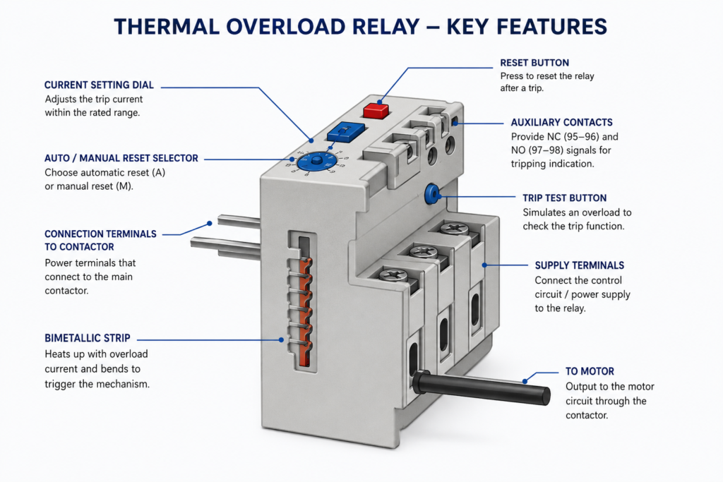
Adjustable Current Setting
Thermal overload relays usually have an adjustable current dial.
This dial is set according to the motor rated current. For example, a relay may cover a current range such as 4–6 A, 6–8 A, 9–13 A, and so on. The correct relay range must be selected first, then the dial is adjusted to match the motor nameplate current.
This setting is very important.
If the overload relay is set too low, the motor may trip unnecessarily during normal operation.
If it is set too high, the motor may not be protected properly.
The overload setting should normally match the motor rated current according to the motor nameplate and the applicable electrical design rules. In real installations, the complete starter design should also consider service factor, starting conditions, motor type, and local standards.
But as a basic rule: do not just turn the dial up because the motor keeps tripping.
That is how small faults become expensive faults.
Manual and Automatic Reset
After a thermal overload relay trips, it must reset before the motor can be started again.
Many overload relays allow two reset modes:
- Manual reset
- Automatic reset
In manual reset mode, someone must press the reset button after the relay cools down. This is usually safer because it forces a person to check the machine before restarting.
In automatic reset mode, the relay resets itself after the bimetallic strip cools down.
Automatic reset can be useful in some special applications, but it must be used carefully. If the motor restarts unexpectedly after cooling, it can create a safety risk or damage equipment.
For most machinery, manual reset is often preferred because a motor overload is a fault condition, not something to ignore and restart blindly.
A tripped overload is the machine saying, “Something is wrong.”
Better to listen.
Test Button
Many thermal overload relays include a test button.
The test button is used to check whether the auxiliary contacts and control circuit respond correctly. When pressed, it simulates a trip condition by changing the contact state.
This is useful during commissioning and maintenance.
For example, pressing the test button should open the NC contact, de-energize the contactor, and stop the motor control circuit. The NO contact should also change state and activate the fault indication if wired.
This does not fully test the thermal behavior of the relay under real overload current, but it does confirm that the control circuit reacts correctly to an overload trip.
Small test. Very useful.
Using Current Transformers for Large Motors
For smaller and medium-sized motors, the motor current usually passes directly through the thermal overload relay.
For larger motors, this may not be practical because the current is too high. In such cases, current transformers can be used.
The motor current passes through the primary side of the current transformer, and the overload relay is connected to the lower secondary current. The relay then reacts to the scaled current instead of the full motor current.
This is common for higher-current motor applications.
The exact current level where current transformers are used depends on the equipment design, but in many systems this becomes relevant for larger motor currents, often around tens of amps and above.
Correct CT ratio selection and correct overload relay setting are critical. A wrong CT ratio can make the overload protection useless or cause nuisance trips.
What Happens During an Overload Trip?
During an overload, the sequence is usually like this:
- The motor draws more current than allowed.
- The overload relay heating elements warm up.
- The bimetallic strips bend.
- The trip mechanism is released.
- The NC auxiliary contact opens.
- The contactor coil loses power.
- The contactor opens the main power contacts.
- The motor stops.
- The NO auxiliary contact may close for fault indication.
- The relay must cool before reset.
This trip delay is intentional.
A motor should not trip instantly on every small current increase. Starting current, short load changes, and brief mechanical resistance are normal. The overload relay is designed to tolerate short peaks but trip when the overload lasts too long.
That is why thermal overload protection follows the heating behavior of the motor better than a simple instantaneous current switch.
Common Applications
Thermal overload relays are used in many motor control applications.
Typical examples include:
- Conveyor motors
- Pumps
- Fans
- Compressors
- Mixers
- Machine tool motors
- Packaging machines
- Industrial production lines
- Small and medium motor starters
- HVAC motors
- Process equipment
They are especially common in direct-on-line starters and reversing starters, where a contactor controls the motor and the overload relay provides motor current protection.
Even in modern automation systems, where motor protection breakers, soft starters, and VFDs are widely used, thermal overload relays are still found in many control panels.
Why?
Because they are simple, affordable, and effective for many standard motor applications.
Thermal Overload Relay vs Circuit Breaker
A thermal overload relay should not be confused with a circuit breaker.
A circuit breaker or fuse protects against short circuits and high fault currents. These faults must be interrupted very quickly because the current can be extremely high.
A thermal overload relay protects against overloads, where the current is too high for normal operation but not necessarily high enough to trip a short-circuit protective device immediately.
In many motor starters, both protections are needed:
- Fuse or circuit breaker for short-circuit protection
- Thermal overload relay for motor overload protection
- Contactor for switching
Each device has its own job.
Mixing them up is not a good idea.
Advantages of Thermal Overload Relays
Thermal overload relays have several practical advantages.
They are simple. They are widely available. They are easy to set. They work well with contactors. They provide protection based on motor heating behavior. They also provide auxiliary contacts for control and fault indication.
Main advantages include:
- Reliable motor overload protection
- Simple working principle
- Adjustable current setting
- Manual or automatic reset options
- Auxiliary contacts for control and alarm signals
- Three-phase monitoring
- Good integration with contactors
- Low maintenance
- Cost-effective protection
- Easy troubleshooting
They are not the newest or smartest motor protection devices, but they still do the job in many applications.
And in automation, “does the job” is often exactly what you want.
Limitations of Thermal Overload Relays
Thermal overload relays also have limitations.
They are slower than electronic protection devices. Their operation depends on heat, so ambient temperature can influence behavior. They do not provide detailed diagnostics unless combined with additional monitoring. They do not usually protect against short circuits. They may not detect all motor faults as precisely as electronic motor protection relays.
Possible limitations include:
- Not suitable as short-circuit protection
- Slower response than electronic protection
- Less diagnostic information
- Possible influence from ambient temperature
- Manual setting required
- Incorrect setting can reduce protection
- May not be ideal for frequent starts or special motor duty cycles
For more advanced applications, electronic overload relays or motor protection relays may be better. These can provide phase loss detection, phase imbalance protection, ground fault detection, temperature input, communication, and detailed diagnostics.
Still, for many standard motor starters, the thermal overload relay remains a practical solution.
Final Thoughts
A thermal overload relay protects an electric motor from damage caused by prolonged overcurrent.
It does this by sensing motor current, heating a bimetallic strip, and tripping an auxiliary contact when the current remains too high for too long. The overload relay does not usually switch the main motor power directly. Instead, it opens the control circuit of the contactor, causing the contactor to disconnect the motor.
That distinction matters.
The contactor switches power.
The overload relay protects the motor.
Together, they form one of the most common motor starter systems in industrial automation.
Thermal overload relays are simple devices, but they are not unimportant. A correctly selected and correctly adjusted overload relay can prevent burned windings, damaged machines, and unnecessary downtime.
A badly set one, on the other hand, is almost decoration.
So set the current properly, wire the NC contact into the control circuit, use the NO contact for fault indication, test the trip function, and take overload trips seriously.
Because when a motor draws too much current, it is usually trying to tell you something.