A thermal overload relay protects an electric motor from operating with excessive current for too long.
It is normally installed directly below a contactor, forming part of a motor starter. The contactor switches the motor on and off, while the overload relay watches the current flowing through all three phases.
One important detail: a thermal overload relay does not provide short-circuit protection. A fuse, MCB or motor-protection circuit breaker is still required upstream.
How a Thermal Overload Relay Works
The motor current passes through heating elements inside the relay.
When the current remains above the selected value, these elements heat bimetallic strips. The strips bend as their temperature rises and eventually activate the relay’s trip mechanism.
Once tripped, the overload relay changes the state of its auxiliary contacts. The normally closed contact opens, causing the contactor coil to de-energize and disconnect the motor.
This delayed thermal response allows the motor to tolerate normal starting current without tripping immediately. However, sustained overload current eventually stops the motor before excessive heating damages its windings.
Many overload relays also respond to phase-loss or severe phase-imbalance conditions.
Power-Circuit Connections
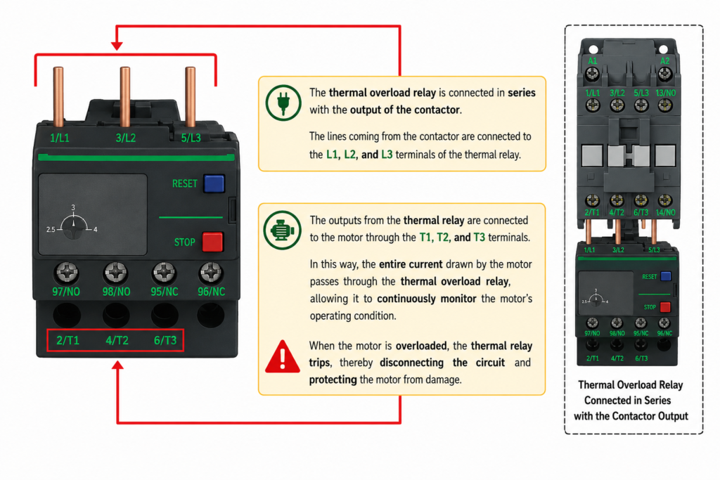
A three-phase thermal overload relay is connected in series between the contactor and the motor.
The contactor outputs connect to the overload relay inputs:
- Contactor T1 → Overload 1/L1
- Contactor T2 → Overload 3/L2
- Contactor T3 → Overload 5/L3
The motor connects to the overload relay outputs:
- Overload 2/T1 → Motor phase U
- Overload 4/T2 → Motor phase V
- Overload 6/T3 → Motor phase W
Because the complete motor current passes through the overload relay, it can continuously monitor the motor load.
Auxiliary Control Contacts
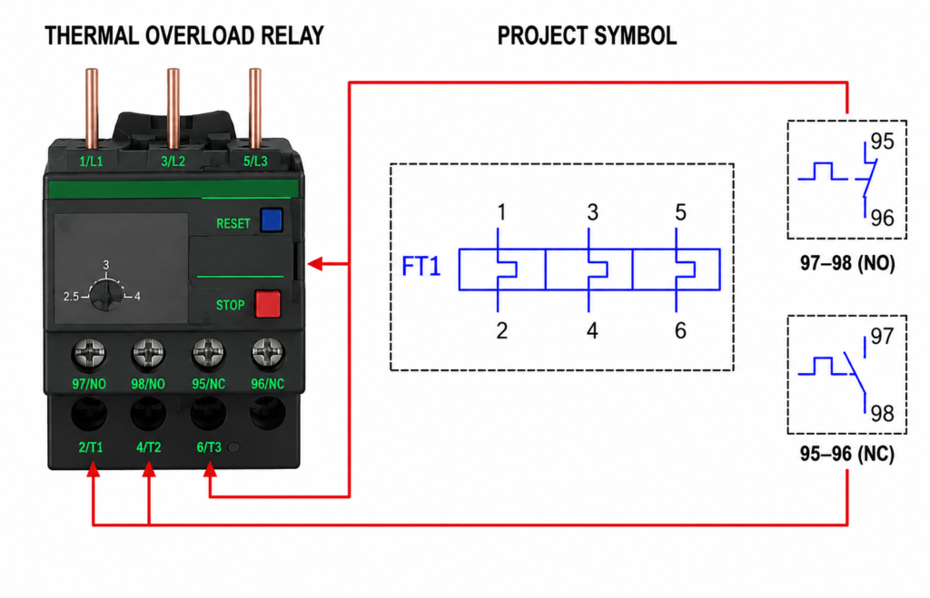
Thermal overload relays normally include two auxiliary contacts.
Normally Closed Contact: 95–96
Under normal operating conditions, terminals 95–96 are closed.
This contact is usually wired in series with the contactor coil. When the overload relay trips, 95–96 opens and removes power from the coil. The contactor drops out, opening the main power contacts and stopping the motor.
Normally Open Contact: 97–98
Under normal conditions, terminals 97–98 are open.
When the overload relay trips, this contact closes. It can be used for:
- PLC fault indication
- HMI alarm messages
- Warning lamps
- Alarm relays
- Maintenance notifications
The 97–98 contact normally reports the trip; it does not usually interrupt the contactor coil circuit.
Setting the Overload Current
The adjustment dial should be set according to the motor nameplate current and the equipment manufacturer’s instructions.
Setting it too low may cause nuisance trips during normal operation. Setting it too high may allow the motor to overheat before protection operates.
Do not simply increase the setting whenever the relay trips. First check for:
- Mechanical overload
- Missing phase
- Low voltage
- Current imbalance
- Incorrect motor connection
- Frequent starting
- Poor motor cooling
- Worn bearings
A tripping overload relay is often reporting a real motor or machine problem.
Reset and Test Controls
Most overload relays include:
- Manual or automatic reset selection
- Reset button
- Stop or trip button
- Test function
- Trip indicator
Manual reset is generally safer for machinery because the motor cannot restart automatically as soon as the relay cools.
After a trip, identify the cause before resetting the relay and restarting the motor.
Schematic Designation
In electrical drawings, a thermal overload relay may be identified as F, FR, OL, FT or another project-specific reference.
Its main current paths are shown as three linked elements, while auxiliary contacts 95–96 and 97–98 are normally drawn separately in the control circuit.
Final Thoughts
The contactor and overload relay perform different jobs.
The contactor switches the motor power. The thermal overload relay monitors motor current and trips when an overload lasts long enough to become dangerous.
Understanding terminals 1/L1 through 6/T3, together with auxiliary contacts 95–96 and 97–98, makes motor-control circuits much easier to wire and troubleshoot.