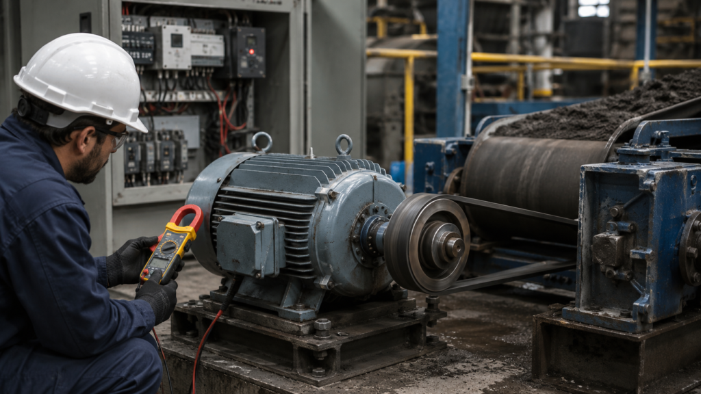
A three-phase motor starts normally and sounds reasonably healthy with no load. The trouble appears only when the machine begins working.
The conveyor slows down. The mixer struggles. The pump cannot build normal pressure. Motor current climbs, yet the shaft does not produce the torque it should.
This fault is easy to misdiagnose because the motor is clearly running. That does not prove it has a healthy three-phase supply, the correct terminal connection or enough capacity for the driven load.
The best approach is to compare the electrical supply, motor current, actual speed and mechanical load—preferably while the problem is happening.
Work Safely Before Testing
Three-phase motor circuits contain hazardous voltage and high fault-current capacity.
Before opening terminal boxes, tightening connections or disconnecting the load:
- Isolate and lock out the power
- Confirm the absence of voltage
- Wait for any VFD DC bus to discharge
- Secure machinery against stored or gravitational energy
- Follow the site’s electrical safety procedure
Running measurements should only be performed by qualified personnel using correctly rated instruments and protective equipment.
Step 1: Confirm That the Motor Is Actually Losing Torque
Start by describing the fault precisely.
Does the motor:
- Run normally when uncoupled?
- Slow down only after material enters the machine?
- Struggle from the moment it starts?
- Run well when cold but weaken after heating?
- Draw high current on all phases?
- Draw very different current on each phase?
- Reach normal speed but fail to move the load?
A loaded induction motor naturally slows slightly as load increases. This difference between synchronous speed and rotor speed is called slip. Increasing load requires more torque, so slip and motor current rise. A small speed reduction is normal; a dramatic slowdown is not.
Measure the actual shaft speed with a tachometer and compare it with the nameplate speed. Do not judge speed only by sound.
Step 2: Check the Driven Equipment First
Sometimes the motor is healthy and the load has simply become much harder to move.
Inspect the machine for:
- A jammed conveyor
- Product buildup
- A blocked pump impeller
- A seized gearbox
- Dry or damaged bearings
- Incorrect belt tension
- Misaligned couplings
- A brake that does not release fully
- A closed valve or blocked pipe
- Increased material viscosity
- An incorrect gear ratio
Siemens notes that industrial processing equipment can demand very high torque and that blockages or changes in the process can overload the entire drive train.
Where it can be done safely, uncouple the motor and test the machine and motor separately. A motor that reaches speed easily when disconnected but struggles when recoupled points toward excessive load, incorrect sizing or a mechanical fault.
Step 3: Measure All Three Line Voltages
Do not measure one phase pair and assume the rest are identical.
Measure:
- L1 to L2
- L2 to L3
- L3 to L1
Take readings at the motor starter or drive input, and at the motor terminals where practical. Most importantly, measure while the motor is loaded.
A supply can look normal when the motor is stopped and collapse after current begins flowing.
Low voltage reduces the torque available from an induction motor. The effect can be larger than expected because motor torque at a fixed frequency changes approximately with the square of the applied voltage. A motor receiving 90% of its intended voltage may therefore develop only around 81% of the expected torque.
Possible causes of low voltage include:
- Undersized supply cables
- Long cable runs
- An overloaded transformer
- Weak generator supply
- Loose terminals
- Damaged contactor contacts
- Incorrect transformer tap setting
- Excessive voltage drop elsewhere in the installation
Follow the voltage through the circuit until you find where it is being lost.
Step 4: Look for Voltage and Current Imbalance
Three line-to-line voltage readings can all appear close to nominal while still being unbalanced.
Even a small voltage imbalance can produce a much larger current imbalance and additional motor heating. NEMA guidance calls for motor derating when voltage unbalance exceeds 1%.
Measure the current in all three motor leads under the same operating condition.
A useful pattern is:
- All currents similarly high: The motor may be overloaded, undersized, incorrectly connected or operating with low overall voltage.
- One current unusually low or zero: Suspect phase loss, an open winding or a failed connection.
- One or two currents much higher: Suspect voltage imbalance, high-resistance connections, winding damage or supply problems.
- Current normal but shaft torque poor: Check motor connection, VFD settings, coupling and internal rotor condition.
Do not rely only on the overload relay setting or VFD current display. Use a clamp meter to compare the actual phase currents.
Step 5: Check for Single Phasing
A motor that loses one phase while already running may continue turning, particularly when lightly loaded. Its available torque drops sharply, phase currents become unbalanced and the motor can overheat quickly.
Check:
- All incoming fuses
- Circuit-breaker poles
- Contactor main contacts
- Overload-relay terminals
- Motor isolators
- Cable joints
- Terminal links
- Motor winding continuity
A fuse can look intact while being open internally. A contactor can also pull in normally while one main contact is badly burned.
Measure voltage on both sides of each switching device under load. Voltage measured with no current flowing may hide a high-resistance connection.
Three-phase motor manufacturers commonly recommend phase-failure protection because continued operation with a missing phase can damage the motor.
Step 6: Verify the Star or Delta Connection
An incorrectly linked terminal box is one of the most common causes after a motor replacement.
Check the nameplate carefully.
A motor marked 230/400 V Δ/Y is normally:
- Delta at 230 V
- Star at 400 V
A motor marked 400/690 V Δ/Y is normally:
- Delta at 400 V
- Star at 690 V
Suppose a 400/690 V motor is connected in star to a 400 V supply. Each winding receives only about 230 V instead of its intended 400 V. The motor may run without load but develop far less torque when the machine is loaded.
Do not copy the terminal links from the old motor without comparing both nameplates. Motors with the same power and frame size can have different voltage ratings.
Also inspect the terminal links for looseness, corrosion or one missing bridge.
Step 7: Confirm the Motor Is Correctly Sized
A motor can be electrically healthy and still be too small.
Compare the application requirements with the nameplate:
- Rated power
- Rated torque
- Rated current
- Rated speed
- Duty class
- Service factor, where applicable
- Starting method
- Number of starts per hour
Torque demand is not always constant. Conveyors, crushers, mixers and positive-displacement machines may require considerable breakaway or peak torque. Fans and centrifugal pumps behave differently because their load changes strongly with speed.
Do not size a motor only from its normal running power. Starting torque, acceleration time and temporary process overloads also matter. Siemens identifies breakaway torque as a leading motor-selection factor in demanding processing applications.
Step 8: Check the Motor’s Rotation Direction
A motor rotating in reverse can still appear to run normally.
However, a pump, fan or screw conveyor may perform extremely poorly in the wrong direction. A centrifugal pump may produce little pressure, and a fan may move much less air even though the shaft is close to normal speed.
Compare rotation with the arrow on the pump, fan, gearbox or machine housing.
To reverse a direct-on-line three-phase motor, isolate the supply and interchange any two phases according to the approved procedure. For a VFD-controlled motor, use the drive configuration or approved output-wiring procedure.
Step 9: Check VFD Frequency and Voltage
When the motor is supplied by a variable frequency drive, confirm the actual output frequency.
A standard motor cannot produce rated mechanical power when it is commanded to run far below its rated speed unless the application and drive system were designed for that condition.
Below base speed, a correctly configured VFD can normally maintain approximately rated torque by adjusting voltage with frequency. Above base speed, available torque generally falls because the motor enters the field-weakening region.
Check:
- Maximum frequency
- Base or rated frequency
- Rated motor voltage
- Motor current
- Motor power
- Rated speed
- Control mode
- Torque limit
- Current limit
- Voltage boost
- Slip compensation
- Acceleration settings
A 50 Hz motor accidentally configured with a 60 Hz base frequency—or the opposite—can receive the wrong voltage-to-frequency ratio.
Siemens explains that a frequency converter controls both output voltage and frequency, which directly influences motor speed and torque production.
Step 10: Review Current and Torque Limits
The VFD may be intentionally restricting the motor.
Look at live values for:
- Output current
- Current limit active
- Torque reference
- Torque limit active
- Speed reference
- Actual speed
- DC bus voltage
- Output frequency
If the current limit is set too low, the drive cannot supply enough current to produce the required torque. The motor may accelerate with no load and then slow down as soon as the machine begins working.
The same applies to a soft starter during acceleration. WEG warns that an excessively low current-limit setting may not provide enough torque to start or accelerate the load.
Do not simply increase the limit to its maximum. Confirm that the motor, drive, cables and mechanical equipment can safely handle the resulting current and torque.
Step 11: Perform Motor Identification or Autotuning
Vector-control drives depend on accurate motor data.
If the following values are wrong, torque control can be poor:
- Rated voltage
- Rated current
- Rated frequency
- Rated speed
- Rated power
- Power factor
Enter the values directly from the motor nameplate, then perform the manufacturer’s recommended static or rotating motor-identification procedure.
Before a rotating autotune, uncouple or secure the machine as required. The motor may move unexpectedly.
If the drive was replaced or factory-reset, do not assume its default parameters match the connected motor.
Step 12: Inspect the Motor Internally
After eliminating supply, connection, drive and load problems, the motor itself may be damaged.
Possible internal faults include:
- Shorted stator turns
- High-resistance winding connections
- Cracked rotor bars
- Damaged end rings
- Rotor rubbing
- Worn bearings
- Incorrect air gap
- Previous overheating damage
Broken rotor bars often become most noticeable under load. The motor may vibrate, produce fluctuating current, make a rhythmic sound or struggle to generate normal torque.
Basic resistance measurements may not reveal every winding or rotor fault. Further testing may require insulation-resistance testing, winding-resistance comparison, current-signature analysis, surge testing or examination by a motor repair specialist.
Fast Troubleshooting Order
Use this sequence when a three-phase motor runs but loses torque:
- Check whether the driven equipment is jammed or overloaded.
- Measure actual motor speed under load.
- Measure all three line voltages while loaded.
- Compare current on all three phases.
- Inspect fuses, contactors, terminals and cables for phase loss.
- Verify star or delta links against the nameplate.
- Confirm rotation direction.
- Check whether the motor is large enough for the load.
- Review VFD frequency, motor data and control mode.
- Check current and torque limits.
- Perform motor identification where required.
- Test the motor for winding, rotor and bearing faults.
Final Thoughts
A three-phase motor that runs without load but becomes weak under load is giving you an important clue.
It can rotate, but either the motor is not receiving the correct electrical conditions, the controller is limiting its output, the motor is incorrectly connected, or the machine demands more torque than the drive system can provide.
Begin with loaded voltage and current measurements. Those readings usually tell you whether to continue toward the electrical supply, the motor itself or the mechanical equipment.
Change one thing at a time. Otherwise, a loose terminal, incorrect star connection and overloaded gearbox can easily become mixed together—and the real cause remains hidden.