A time delay relay is a control device that changes the state of its output contacts after a preset period.
It is commonly used when electrical equipment must start or stop after a deliberate delay. Typical applications include motor starting sequences, ventilation systems, pumps, lighting control and industrial automation.
The relay shown here operates as an on-delay timer. Timing begins when voltage is applied to the relay coil. After the selected time expires, the output contact changes state.
Coil Terminals A1 and A2
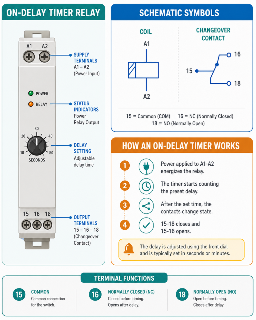
The timer relay is powered through terminals:
- A1
- A2
The voltage applied across these terminals must match the relay’s rated supply voltage.
For example, with a 230 V AC timer:
- A1 may be connected to phase through a fuse or circuit breaker.
- A2 may be connected to neutral.
Other versions may use 24 V AC, 24 V DC or another control voltage. Always check the voltage printed on the relay before wiring it.
When the correct voltage is applied, the relay becomes energized and starts counting the selected delay.
Time Adjustment
The adjustment knob sets how long the relay waits before changing its output contacts.
Depending on the model, the range may be:
- Fractions of a second
- Several seconds
- Minutes
- Hours
If the relay is set to five seconds, its coil energizes immediately, but its timed contact does not change until approximately five seconds have passed.
Timer accuracy and reset behaviour vary by model, so the manufacturer’s instructions should be checked for precise applications.
Output Contacts 15, 16 and 18
A typical timer relay includes a changeover contact:
- 15 — Common
- 16 — Normally closed
- 18 — Normally open
Before the timer finishes:
- Contact 15–16 is closed.
- Contact 15–18 is open.
After the preset delay expires:
- Contact 15–16 opens.
- Contact 15–18 closes.
This allows one device to be switched off while another is switched on after the delay.
Contactor Control Example
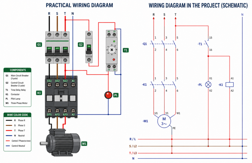
In a basic motor circuit, the timer relay can control the coil of a contactor.
The control phase is connected to terminal 15. Terminal 18 is connected to the contactor coil terminal A1, while the contactor’s A2 terminal connects to neutral.
The sequence works like this:
- Voltage is applied to timer terminals A1 and A2.
- The relay begins timing.
- Contact 15–18 remains open during the delay.
- When the set time expires, 15–18 closes.
- The contactor coil energizes.
- The contactor’s main contacts close.
- Three-phase power reaches the motor.
The motor therefore starts only after the selected delay.
Using the Normally Closed Contact
Terminal 16 may be connected to an indicator lamp.
While the timer is counting, contact 15–16 remains closed and the lamp stays on.
When the delay finishes, 15–16 opens and the lamp switches off. At the same moment, 15–18 closes and energizes the contactor.
This provides a simple visual indication that the timer is waiting.
Important Considerations
Not every time relay operates in the same way. Other timer functions include:
- Off-delay
- Interval timing
- Pulse timing
- Cyclic operation
- Star-delta timing
- Multifunction timing
Always confirm the selected operating mode before commissioning the circuit.
The relay contact rating must also be suitable for the connected load. Timer contacts are normally used to control a contactor coil or another small control load—not the motor directly.
Final Thoughts
A time delay relay provides a simple way to control when equipment starts or stops.
Terminals A1 and A2 supply the timer, terminal 15 is common, terminal 16 is normally closed and terminal 18 is normally open.
In an on-delay circuit, the relay waits for the selected time, opens 15–16 and closes 15–18. This can energize a contactor and start a motor automatically after a controlled delay.