When a VFD and motor are installed close together, wiring is usually simple. Short motor cables, short feedback cables, fewer signal problems.
But in real industrial machines, things are not always that convenient.
Sometimes the VFD is mounted in an electrical cabinet, while the motor is located far away on the machine. This creates two common problems:
First, long motor cables can cause voltage spikes because of the fast PWM switching from the VFD. This is often handled with output chokes, dV/dt filters, or sine wave filters.
Second, in closed-loop systems, long encoder cables can cause feedback signal problems.
This article focuses on the second problem: long encoder cable runs.
If the encoder signal becomes weak, noisy, or distorted, the VFD may not receive correct motor feedback. This can lead to unstable motor control, random encoder faults, nuisance trips, or incorrect speed and position feedback.
Let’s look at why this happens and how to reduce the problem.
Why Long Encoder Cables Can Cause Problems
An encoder cable carries feedback signals from the encoder to the VFD or motion controller.
In a closed-loop VFD system, this feedback is very important. The drive uses it to know the motor speed, direction, and sometimes position.
The problem is that every cable has resistance.
The longer the cable, the higher the total resistance. Higher resistance causes more voltage drop.
This means the signal voltage that leaves the encoder may not be the same voltage that reaches the drive input.
For example, an encoder may send a 5 V signal, but after traveling through a long cable, the drive may receive a lower voltage. If the voltage drops too much, the drive may no longer recognize the signal correctly.
That is when strange problems begin.
The motor may run roughly.
The drive may trip randomly.
Encoder faults may appear.
The machine may work one day and cause problems the next.
These are often the most annoying faults because they do not always happen consistently.
TTL Encoder Signals and Voltage Drop
Many incremental encoders use TTL signals.
TTL encoders normally operate around 5 V. Because this voltage is quite low, there is not much room for voltage drop.
If the signal voltage drops too far, the VFD encoder input may no longer see a clear “high” signal.
For example, if the encoder outputs 5 V but the long cable causes a 1 V drop, the drive may only receive around 4 V. Depending on the encoder input requirements, this may be too low or very close to the limit.
This can cause random encoder faults.
A common symptom is that the A and B encoder channels, or their complementary signals, do not match correctly. The drive then detects a feedback error and trips.
If you are seeing random encoder faults on a long cable run, voltage drop should be one of the first things to check.
1. Use the Shortest Practical Encoder Cable
This sounds obvious, but it is often overlooked.
Use the shortest encoder cable that is practical for the application.
In many installations, technicians use a standard cable length because it is already available. For example, the machine may only need 35 meters of cable, but a 75-meter cable is installed because it was on the shelf.
That extra cable is not harmless.
A longer cable means:
More resistance
More voltage drop
More chance of noise pickup
More cable to route and protect
More possible failure points
If the encoder cable is much longer than needed, replace it with a shorter one.
This is one of the easiest ways to improve signal quality.
2. Check the Encoder Cable Resistance
Before choosing an encoder cable, check the cable datasheet.
The cable resistance is usually listed as a value per length, such as:
Ohms per meter
Ohms per foot
The total cable resistance depends on the cable length.
A longer cable has more resistance. More resistance causes more voltage drop.
The basic idea is:
Voltage drop = Current × Resistance
So if the encoder draws more current, or the cable has higher resistance, the voltage drop will increase.
For long encoder runs, choose a cable with lower resistance. This usually means using larger conductor sizes or a cable designed specifically for long feedback runs.
Do not treat all encoder cables as the same. They are not.
3. Increase the Encoder Supply Voltage, If Allowed
Some encoders are powered directly from the VFD encoder card.
With some TTL push-pull encoders, the output signal level depends on the supply voltage. If the encoder receives a lower voltage because of cable voltage drop, the output signal may also become weaker.
In this case, increasing the encoder supply voltage slightly can help compensate for voltage loss in the cable.
However, this must be done carefully.
Before increasing supply voltage:
Check the encoder datasheet
Check the encoder card manual
Measure the actual voltage at the encoder
Make sure the encoder can handle the higher voltage
Do not exceed the manufacturer’s limits
Never guess here. Too much voltage can damage the encoder.
If the encoder card allows supply voltage adjustment, raising it slightly may improve signal reliability on long cable runs.
4. Power the Encoder Locally
Another option is to power the encoder directly at the motor or machine side.
Instead of sending encoder supply voltage all the way from the VFD cabinet through a long cable, a separate power supply can be installed closer to the encoder.
This can reduce voltage drop on the encoder supply wires.
In some cases, it can also reduce the total voltage drop affecting the feedback signals.
But again, check the encoder datasheet first.
Some encoders must be powered from the drive encoder card. Others allow external power. Some encoders can accept a wider input voltage, such as 24 V, and internally regulate the electronics.
Local encoder power can be a very good solution, especially on long-distance installations.
Just make sure the grounding, shielding, and signal reference are wired correctly. Poor grounding can create new problems.
5. Consider Using HTL Instead of TTL
If the system supports it, HTL encoder signals can be a better choice for long cable runs.
TTL signals are usually based around 5 V.
HTL signals are usually based around 24 V.
Because HTL uses a higher signal voltage, it can tolerate more voltage drop before the drive has trouble reading the signal.
For example, a 5 V TTL signal does not have much margin. Losing even 1 V can be a problem.
A 24 V HTL signal has much more room before it falls below the required “high” level.
This makes HTL more suitable for longer cable distances and electrically noisy environments.
However, this is very important:
The VFD or controller encoder input must support HTL.
Do not connect an HTL encoder signal to a TTL-only input unless the hardware is designed for it. You could damage the encoder card or drive input.
Always confirm the encoder type and input card type before changing from TTL to HTL.
6. Use a Better Encoder Cable for Long Runs
For long feedback cables, cable quality matters a lot.
A proper encoder cable should have:
Low conductor resistance
Good shielding
Correct twisted pairs
Suitable insulation
Good noise protection
Correct cable rating for the environment
For long distances, use encoder cables designed for long feedback runs. These often use larger conductors to reduce resistance and voltage drop.
Shielding is also important because encoder signals can be affected by electrical noise from motor cables, contactors, relays, braking resistors, and other industrial equipment.
When routing encoder cables, avoid running them directly beside motor power cables for long distances.
If they must cross, try to cross them at 90 degrees.
Also make sure the cable shield is connected according to the drive and encoder manufacturer’s recommendations.
Bad shielding or poor cable routing can make a good encoder system behave badly.
7. Use a Signal Repeater
A signal repeater can help when the encoder cable run is too long or when the signal needs to be shared with multiple devices.
A repeater receives the encoder signal, conditions it, and sends out a stronger, cleaner version of the signal.
Signal repeaters can help with:
Long cable runs
Weak encoder signals
Noise problems
Multiple drive or controller inputs
Signal splitting applications
This can be useful when replacing the cable is not practical or when the machine layout requires a long distance between the encoder and the drive.
When selecting a signal repeater, make sure it supports the encoder signal type you are using, such as TTL, HTL, incremental, or differential signals.
Also check the maximum frequency and cable distance ratings.
8. Use Remote Encoder I/O or Fieldbus Modules
Another modern solution is to use a remote encoder input module near the motor.
Instead of running the raw encoder signal all the way back to the VFD cabinet, the encoder connects to a nearby I/O module. That module then sends the position or speed data over an industrial communication network.
Common examples include:
EtherCAT
PROFINET
EtherNet/IP
CANopen
Other real-time fieldbus systems
This can reduce the need for very long encoder cables.
In many cases, standard industrial Ethernet cable is cheaper and easier to route than a long encoder cable.
Another benefit is that the encoder position can become available to the PLC or motion controller directly over the network.
However, there is one important thing to check: delay.
Remote encoder modules can introduce input delay. For many applications this is acceptable, but for high-performance motion control, the delay must be checked carefully.
Before using remote encoder I/O, confirm that the update rate, delay, and accuracy are suitable for the machine.
Extra Practical Tips for Encoder Cable Installation
Long encoder cables are sensitive, so installation quality matters.
Here are some extra tips:
Do not route encoder cables together with motor power cables
Use shielded cable
Ground the shield correctly
Avoid unnecessary cable loops
Check connectors for loose pins
Keep cable runs as short and direct as possible
Use differential encoder signals when possible
Check actual voltage at the encoder and at the drive input
Follow the encoder and drive wiring manuals
A small wiring mistake can create a very strange fault.
And yes, it can waste many hours.
Common Symptoms of Encoder Cable Problems
Long encoder cable problems can show up in different ways.
Common symptoms include:
Random encoder faults
Drive trips during movement
Unstable speed feedback
Motor vibration or rough running
Incorrect direction feedback
Position errors
Nuisance faults that are hard to repeat
Faults that happen more often at higher speed
Faults that appear after cable replacement or rerouting
If the problem is random and the machine uses a long encoder cable, check signal quality, voltage drop, shielding, and grounding.
Final Thoughts
Long encoder cable runs can cause real problems in closed-loop VFD applications.
The main issue is usually voltage drop, noise, or weak feedback signals. TTL encoders are especially sensitive because they use low signal voltage.
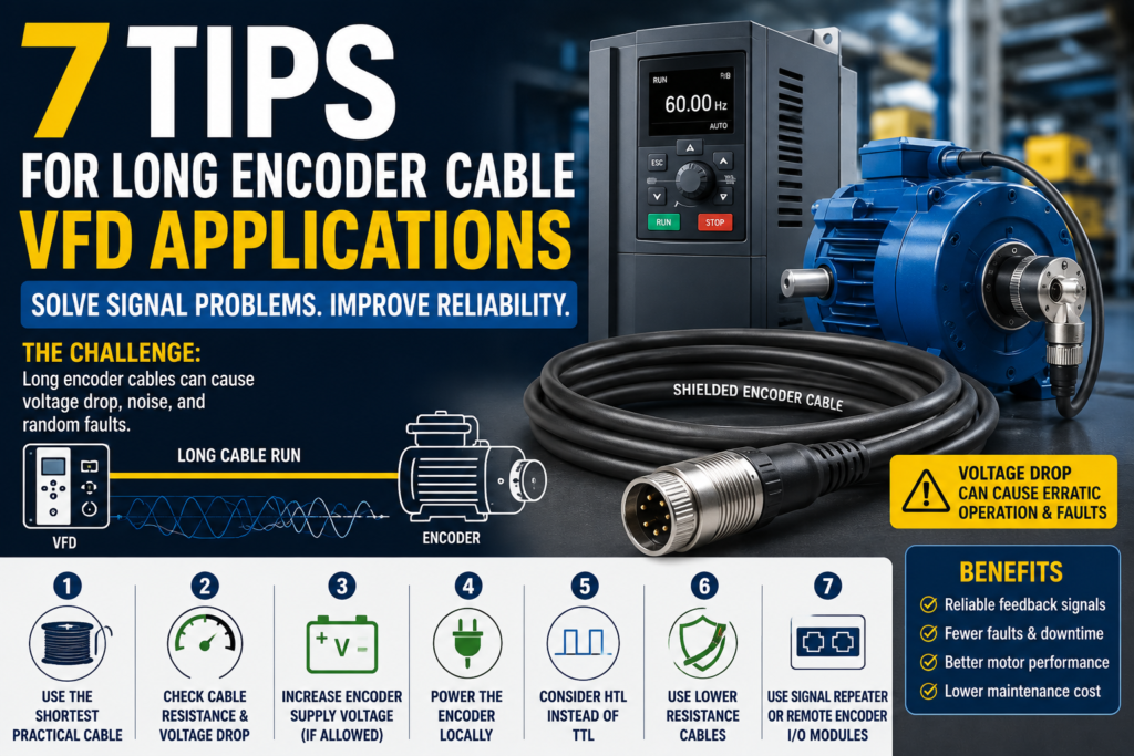
To improve reliability, start with the basics:
Use the shortest practical cable
Check cable resistance
Measure voltage drop
Use proper shielded encoder cable
Increase supply voltage only if allowed
Power the encoder locally if suitable
Consider HTL signals for longer runs
Use a signal repeater or remote encoder I/O when needed
A long encoder cable does not automatically mean trouble. But it does need to be designed properly.
Good cable selection, proper routing, correct shielding, and the right encoder signal type can prevent many frustrating VFD feedback faults.
In closed-loop motor control, the drive is only as good as the feedback signal it receives.