Troubleshooting Diodes becomes much easier when you stop treating the circuit as a collection of mysterious parts and instead ask what the circuit is supposed to do. In this chapter, the important ideas are diodes can short open leak or avalanche from stress, polarity and circuit role matter, flyback and reverse-polarity diodes fail differently, and in-circuit paths can mask faults. These are not isolated facts. Together they create a model of normal operation. Troubleshooting is the process of comparing that model with real measurements and using the differences to narrow the search.
Normal behavior is the reference point for every diagnosis. A healthy diode conducts in its intended direction and blocks where the circuit expects isolation. Before touching a probe, write down the expected supply voltage, the expected state of the control input, the expected output condition, and the expected load response. Even approximate expectations are useful. A prediction such as “this node should be close to the supply” or “there should be almost no voltage across this closed connection” gives the measurement meaning. Without an expectation, a number on a meter can look precise while telling you very little.
The fastest approach is to test the circuit in functional sections. Use diode mode with power removed, then verify voltage and current in operation. If the first measurement is normal, move one block toward the symptom. If it is abnormal, move one block toward the source or reference. This creates a last-known-good point and a first-known-bad point. Once those two boundaries are close together, individual components become worth testing. This is usually faster and safer than removing parts one by one.
Common failure mechanisms in this area include shorted junction, open junction, reversed installation, overheated rectifier, and damaged clamp. Notice that several different faults can produce the same visible symptom. That is why symptoms should not be used as part numbers. A dead load might be caused by the load itself, but it might also be caused by missing supply voltage, an open return, a disabled driver, or a protection device that has operated. The job is to separate those possibilities with measurements.
A useful worked example is this: A reverse-polarity protection diode is shorted, causing the input fuse to open every time power is connected. The important lesson is the sequence, not the specific component. First confirm the condition that should exist before the suspected stage. Then measure the stage itself. Finally confirm the condition after it. If the input is correct and the output is wrong, the stage becomes a strong suspect. If both input and output are wrong, keep tracing upstream. If both are correct, move downstream.
When a result does not make sense, do not immediately assume the meter or the component is bad. Re-check the reference point, probe contact, meter mode, range, and whether the circuit is in the expected operating state. Ask whether another parallel path could change an ohmmeter reading or whether a high-impedance meter could show a “ghost” voltage that cannot supply current. Good troubleshooting includes checking whether the test itself can mislead you.
A strong diagnosis explains more than one observation. It should explain why the symptom appears, why certain measurements are abnormal, and why other parts of the circuit still work. If your theory explains only one reading and conflicts with three others, keep looking. The best next test is the one whose two possible results lead you in clearly different directions. This is the practical meaning of reducing uncertainty.
After the correction, return to the original symptom and repeat the same operating condition. Confirm function, then check supply voltage, load current, important voltage drops, and temperature where relevant. A circuit that works for ten seconds may still have a weak connection, overloaded component, or unstable supply. Verification is part of troubleshooting, not an optional step after troubleshooting.
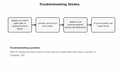
Practical Diagnostic Sequence
- Define the exact symptom and the condition that makes it appear.
- Confirm the correct supply and reference before testing components.
- Use this chapter’s main separating test: Use diode mode with power removed, then verify voltage and current in operation.
- Record measured values with units and polarity where relevant.
- Prove the cause before replacing a part, then verify the repair under load.
Hands-On Practice
- Draw a simple block diagram for troubleshooting diodes with source, control or signal path, and load.
- Write two expected voltage or resistance readings before taking any measurements.
- On a safe low-voltage circuit, create one reversible fault such as an open jumper or missing ground.
- Use no more than three measurements to identify the faulty section.
- Restore the circuit and verify that the original readings return to normal.
Common Traps
- shorted junction
- open junction
- reversed installation
- overheated rectifier
- damaged clamp
Check Your Understanding
- What does normal operation look like for troubleshooting diodes?
- Which single measurement would eliminate the largest number of possible causes?
- Name one fault that could pass a continuity test but fail under load.
- How could the test itself produce a misleading reading in this chapter?
- What measurements would you repeat after the repair to prove the circuit is stable?
Bench Reminder
- Main separating measurement: Use diode mode with power removed, then verify voltage and current in operation
- Write the expected result before you probe.
- If the result is ambiguous, isolate the stage and repeat the test.