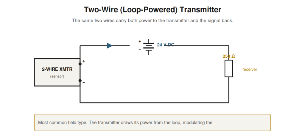
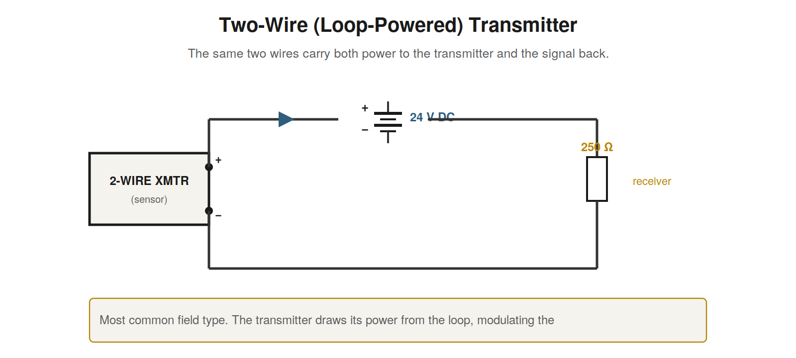
The most common transmitter in the field is the two-wire, loop-powered type, and understanding it is central to understanding practical loops. Its cleverness is that it uses just two wires to do everything: those same two wires both deliver power to the transmitter and carry the signal back. This economy — one pair of wires per loop — is a large part of why the 4–20 mA loop became so widespread, since running a single pair to each field device is simple and cheap.
How two wires do both jobs
The two-wire transmitter works by drawing its operating power from the loop current itself. Because the loop always carries at least 4 mA when working, the transmitter has at least that much current available to power its own electronics, and it regulates the total loop current to between 4 and 20 mA to represent its measurement. So the current serves two purposes at once: it powers the transmitter, and its magnitude is the signal. This is possible because the transmitter’s electronics are designed to operate on very little power — within the 4 mA minimum — leaving the regulation of current above that as the signal. The elegance is that a single pair of wires carries power out and signal back simultaneously, with no separate power wiring needed at the field device. This is why the two-wire loop-powered transmitter is the workhorse of field instrumentation: minimal wiring, and the loop powers the device.
The voltage budget of a two-wire loop
Because the two-wire transmitter draws its power from the loop, it needs a minimum voltage across its terminals to operate — and this is a key constraint in loop design and a source of faults. The supply voltage must be enough to provide this minimum transmitter voltage plus the drops across the wiring and the sense resistor at the full 20 mA. If the supply is too low, the wiring too long and resistive, or too many devices are added, the transmitter may not get its minimum voltage at high current, and the loop fails to work correctly at the top of its range. Reading a loop’s voltage budget — supply voltage against the sum of the transmitter minimum plus the resistive drops at 20 mA — tells you whether the loop has enough voltage to function, and is essential when designing or modifying a loop or diagnosing a loop that reads correctly at low current but fails at high current, a classic symptom of an inadequate voltage budget.
Polarity and connection
Two-wire transmitters are polarity-sensitive: the two terminals are marked plus and minus, and the loop must be connected so the current flows in the correct direction through the transmitter. Reversing the connections usually prevents the transmitter from working, since its internal electronics and any reverse-polarity protection expect current in one direction. When wiring or troubleshooting a two-wire loop, observing the polarity — connecting the supply, transmitter, and receiver so the current circulates correctly — is essential, and a reversed connection is a simple but real cause of a non-working loop. The convention is straightforward once understood: the current leaves the supply positive, flows through the loop in series (through the transmitter in its correct polarity and the receiver), and returns to the supply negative, and every device in the loop must be connected consistent with this single direction of current flow.
Why two-wire won
The two-wire loop-powered transmitter became the dominant field device for a compelling practical reason: wiring cost and simplicity. In a plant with hundreds or thousands of measurement points, the cost of running wire dominates, and a device that needs only a single pair — carrying both power and signal — halves or better the wiring compared to a device needing separate power. Multiply that saving across a whole plant and it is enormous, in materials, labor, conduit, and terminations. Beyond cost, fewer wires mean fewer connections to fail, simpler loop diagrams, and easier installation. The two-wire device does impose constraints — it must operate on the limited power the loop provides, and the voltage budget must be respected — but for the vast majority of measurements these constraints are easily met, and the wiring savings are decisive. This is why, when you walk into a plant and look at the transmitters, most will be two-wire loop-powered devices: they solve the measurement problem with the least wire, which at plant scale is exactly what matters.
The minimum-voltage constraint in practice
The two-wire transmitter’s need for a minimum operating voltage is the constraint that most often bites in practice, and understanding it prevents a class of puzzling faults. The transmitter’s electronics need a certain voltage across its terminals to function — commonly around 10 to 12 volts — and this must be available even at 20 mA when the resistive drops are greatest and the leftover voltage for the transmitter is least. A loop designed with too little margin can work fine most of the time but fail when the current rises toward 20 mA, because at high current the drops eat into the transmitter’s voltage until it falls below the minimum. The result is a loop that reads correctly at low values but cannot reach full scale — a distinctive and initially confusing symptom that makes perfect sense once you understand the minimum-voltage constraint. Recognizing this constraint, and checking the voltage budget when a loop fails only at high readings, turns a baffling intermittent-seeming fault into a clear voltage-budget diagnosis.
Scenario: reversed polarity
A simple but real scenario: a newly installed two-wire transmitter would not work at all — the loop read 0 mA as if dead. Power was present and the wiring intact, yet no current flowed. The cause was reversed polarity: the transmitter’s plus and minus terminals had been connected backward, so the loop current, which must flow through the transmitter in one direction, was blocked by the device’s reverse-polarity protection or simply could not energize the electronics. The transmitter, seeing the wrong polarity, did not operate, and the loop read 0 mA. Correcting the connections — swapping the wires to the right polarity — brought the transmitter to life and the loop to normal operation. This scenario is a reminder that a dead loop is not always a broken wire or failed device; on a new or recently worked installation, reversed polarity is a common and easily fixed cause. Checking the polarity of a two-wire transmitter when the loop reads dead, especially after installation or wiring work, catches this straightforward fault that can otherwise be mistaken for a more serious failure.
How the two-wire device regulates current
It illuminates the two-wire transmitter to understand roughly how it regulates the loop current while powering itself. The device sits in the loop and controls how much current flows through it, acting like a variable element that adjusts to set the total loop current to its target. Crucially, it draws its own operating power from this same current — it needs the current to flow to power itself, which is why the minimum is 4 mA (enough to run the electronics), and it regulates the current above that minimum up to 20 mA to represent the measurement. So the device both consumes the loop current (for power) and controls it (for signaling), adjusting itself continuously to hold the current at the value representing its measurement while running on that current. This dual role — powered by the loop, and regulating the loop — is the clever essence of the two-wire device, and understanding it demystifies how one device can be both powered by and the controller of the same current. The 4 mA minimum is the key: it guarantees enough current to power the device even when the measurement is at its lowest, so the device is always powered and always in control.
The two-wire device as the loop’s signature form
The two-wire loop-powered transmitter is so characteristic of the current loop that it is worth seeing as the loop’s signature form — the arrangement that most fully expresses the loop’s virtues. In it, the loop’s advantages combine: one pair of wires carries power and signal, live zero provides the minimum current that powers the device, current signaling gives immunity to wire resistance, and the whole thing is simple and cheap. The two-wire device is where the 4–20 mA design pays off most completely, using every feature of the standard — current, live zero, the 4 mA minimum — to achieve a field device of remarkable economy and robustness. Understanding the two-wire device deeply is therefore understanding the loop at its best, seeing how all its design choices come together in the field device that dominates instrumentation. When you grasp why the two-wire device works — powered by the loop it regulates, needing only a pair of wires, robust over distance — you grasp the essence of what makes the current loop such a successful standard. The two-wire loop-powered transmitter is the loop’s signature achievement, and understanding it is understanding why the loop endures.
The two-wire device in hazardous areas
The two-wire loop-powered transmitter has a special affinity for hazardous areas, and understanding why adds to appreciating its design. In hazardous areas — where flammable gases or dusts may be present — electrical energy must be strictly limited to prevent ignition, and the low power of a two-wire loop suits this well. Because the loop carries only a small current at modest voltage, it is amenable to intrinsic safety techniques that limit energy to safe levels, often via barriers that further constrain the loop’s energy. The two-wire device, running on the loop’s limited power, fits naturally into these energy-limited, intrinsically safe loops that hazardous areas require. This is another reason the two-wire loop is so prevalent in process plants, many of which have hazardous areas: the loop’s inherently low energy suits the safety requirements. Understanding this connection — low-power two-wire loops suiting the energy limits of hazardous areas — explains part of why loops are so common in process industries and introduces the consideration of barriers and intrinsic safety, which add resistance to the loop (affecting the voltage budget) and are part of the loop in hazardous-area installations. The two-wire loop’s low energy is a virtue for hazardous areas, extending its suitability to the demanding environments of process plants.
Respecting the voltage budget in design and diagnosis
The voltage budget of a two-wire loop deserves respect in both design and diagnosis, and keeping it in mind prevents a whole class of problems. In design, respecting the budget means ensuring the supply voltage covers the transmitter minimum plus all the drops at 20 mA, with margin for supply variation, long runs, and any added devices or barriers — so the loop works reliably at full current. In diagnosis, respecting the budget means recognizing the correct-low-fails-high signature as a budget problem and checking the supply voltage and loop resistance when it appears. The budget is the constraint that most often causes subtle two-wire loop problems, and keeping it in mind — designing with adequate margin, diagnosing budget problems when the symptom fits — addresses them. A loop designed with a comfortable voltage budget avoids these problems; one designed at the edge invites them; and one diagnosed with the budget in mind resolves them when they occur. Respecting the voltage budget throughout — ensuring it in design, checking it in diagnosis — is a key part of working competently with two-wire loops, which are constrained by their need for adequate voltage at full current, and honoring that constraint prevents and resolves the budget-related faults that are among the more subtle loop problems.