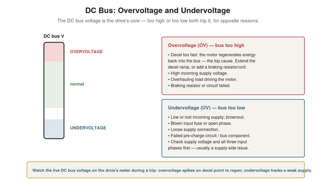
The DC bus voltage is central to the drive, and two of the most
common faults — overvoltage and undervoltage — are defined by it going
too high or too low. These faults are opposites, with opposite causes,
and understanding the DC bus and what drives its voltage up or down is
the key to diagnosing them. Because the DC bus voltage reflects both the
supply and the motor’s behavior, these faults point to distinct areas,
and this chapter explains how to diagnose each.
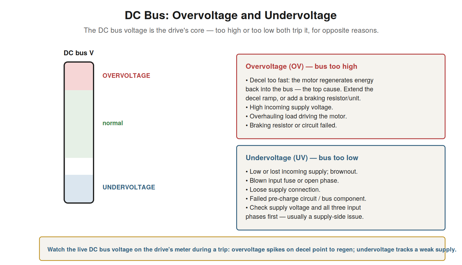
usually from too-fast deceleration causing regeneration, or high supply
voltage; undervoltage (bus too low) is usually a low or lost supply.
Watch the live DC bus voltage to see which way it goes and
when.
Overvoltage
An overvoltage fault means the DC bus voltage rose too high, and the
most common cause is regeneration during too-fast a deceleration. When
the drive decelerates the motor quickly, the motor — slowing a load that
has momentum — acts briefly as a generator, feeding energy back into the
DC bus, which raises the bus voltage. If the deceleration is too fast,
or the load has too much inertia, the returned energy raises the bus
voltage past the overvoltage limit, tripping the drive. This
regeneration-on-deceleration is the leading cause of overvoltage, and
the fix is to extend the deceleration ramp (so the motor slows gently,
returning energy more slowly) or to add a braking resistor or unit that
absorbs the regenerated energy. Other causes of overvoltage include a
high incoming supply voltage (raising the bus), and an overhauling load
that drives the motor. Understanding overvoltage — the DC bus too high,
usually from regeneration on too-fast deceleration — directs the
diagnosis. It reinforces that overvoltage faults, especially those
occurring on deceleration, usually stem from regeneration and are fixed
by slowing the deceleration or adding braking capability, while
overvoltage from a high supply is a supply issue. Watching the live DC
bus voltage during deceleration confirms the regeneration cause — the
voltage climbing as the motor slows — making the diagnosis clear and
pointing to the deceleration ramp or braking as the fix for this common
fault.
Undervoltage
An undervoltage fault means the DC bus voltage fell too low, and the
cause is usually a problem with the incoming supply. The DC bus voltage
derives from the supply through the rectifier, so a low or lost supply
lowers the bus voltage: a low supply voltage, a brownout, a lost phase,
a blown input fuse, or a loose supply connection all reduce the bus
voltage, and if it falls below the undervoltage limit, the drive trips
to protect itself (it cannot operate correctly on too low a bus
voltage). So undervoltage points primarily to the supply side: checking
the incoming supply voltage and all three input phases, the input fuses,
and the supply connections localizes the cause. Other causes include a
failed pre-charge circuit or a DC bus component fault, but the supply is
the first place to look. Understanding undervoltage — the DC bus too
low, usually from a supply problem — directs the diagnosis to the supply
side. It reinforces that undervoltage faults point to the incoming
supply — low voltage, lost phase, blown fuse, loose connection — which
should be checked first, since the bus voltage follows the supply, and a
low bus usually means a low or interrupted supply. Watching the live DC
bus voltage and checking the supply confirms the cause — a low bus
tracking a weak or interrupted supply — making undervoltage a fault that
usually leads to a supply-side problem, diagnosed by checking the supply
voltage, phases, fuses, and connections that feed the DC bus through the
rectifier.
Using the DC bus voltage as a diagnostic
Beyond diagnosing overvoltage and undervoltage themselves, the DC bus
voltage is a valuable diagnostic indicator generally, and understanding
how to use it aids many drive diagnoses. Because the DC bus voltage
reflects both the supply (a low bus indicates a supply problem) and the
motor’s behavior (regeneration raises the bus), watching the live DC bus
voltage reveals what is happening in these areas. A DC bus voltage that
is low points to a supply problem even before an undervoltage trip; one
that climbs on deceleration reveals regeneration even before an
overvoltage trip; a fluctuating bus voltage may indicate a supply or
component problem. So the DC bus voltage, watched live, is a window into
the drive’s core and the supply and motor conditions affecting it.
Understanding how to use the DC bus voltage as a diagnostic — watching
it to reveal supply problems (low bus) and regeneration (rising bus on
decel) — extends its value beyond the specific over/undervoltage faults.
It reinforces monitoring the DC bus voltage as a general diagnostic
practice, because it reflects central conditions — the supply feeding it
and the motor’s energy flow — that affect many faults. Watching the DC
bus voltage live, and understanding what its level and behavior
indicate, makes it one of the most informative values the drive
provides, a diagnostic window into the supply and the motor’s
interaction with the drive that aids the diagnosis of the DC bus faults
and beyond.
Regeneration explained
Because regeneration is the key to understanding overvoltage, it is
worth understanding clearly what regeneration is and when it happens.
Normally, the drive delivers energy to the motor, which drives the load
— energy flows from the drive to the motor. But in certain situations,
the flow reverses: the motor acts as a generator, feeding energy back
into the drive. This happens when the motor is being slowed while
driving a load with momentum (the load’s kinetic energy is returned
through the motor as it decelerates), or when the load actively drives
the motor (an overhauling load, like a descending weight or a fan
windmilling). In these cases, the motor regenerates — sends energy back
— into the drive’s DC bus, raising its voltage. If this returned energy
is more than the drive can handle, the DC bus voltage rises past the
overvoltage limit and the drive trips. Understanding regeneration — the
motor returning energy to the DC bus when slowed against momentum or
driven by an overhauling load — explains the leading cause of
overvoltage. It reinforces that overvoltage, especially on deceleration,
is usually regeneration, and that the fix addresses the returned energy:
slowing the deceleration (returning energy more gently) or adding a
braking resistor (absorbing the returned energy). Understanding
regeneration clearly — what it is and when it happens — is the key to
understanding and fixing overvoltage faults, which are among the most
common drive faults and almost always a matter of the motor regenerating
energy into the DC bus faster than the drive can handle.
Scenario: the crane drive’s overvoltage
A scenario shows overvoltage from an overhauling load. A drive
controlling a crane hoist tripped on overvoltage when lowering a load.
Understanding overvoltage and regeneration explained it: lowering a
load, the weight drives the motor (an overhauling load), so the motor
regenerates energy back into the DC bus, raising its voltage. When
lowering the load, this regeneration pushed the DC bus voltage past the
overvoltage limit, tripping the drive. This is a classic
overhauling-load regeneration scenario: the load (the weight being
lowered) drives the motor, feeding energy back, unlike a normal load the
motor drives. The fix was to provide for the regenerated energy: a
braking resistor to absorb it, letting the drive lower the load without
the DC bus overvoltaging. This scenario shows overvoltage from an
overhauling load — the lowered weight driving the motor and regenerating
— diagnosed through understanding regeneration. Understanding that an
overhauling load (like a lowering weight) drives the motor and
regenerates energy into the DC bus explains this overvoltage, distinct
from the deceleration-regeneration case but the same principle — the
motor returning energy. It reinforces that overvoltage comes from
regeneration, whether from decelerating a load with momentum or from an
overhauling load driving the motor, and that the fix provides for the
regenerated energy (braking resistor). The scenario reinforces
understanding regeneration as the key to overvoltage: here the
overhauling crane load regenerated energy that overvoltaged the DC bus,
resolved by a braking resistor to absorb the energy the lowered load fed
back through the motor.
Braking resistors and units
Because overvoltage from regeneration is so common, understanding
braking resistors and units — the means of handling regenerated energy —
completes the practical picture of overvoltage. When a motor regenerates
energy into the DC bus (decelerating a load or being driven by an
overhauling load), that energy must go somewhere, or it raises the bus
voltage to the overvoltage trip. A braking resistor provides somewhere:
it is a resistor that the drive switches across the DC bus to dissipate
the regenerated energy as heat, keeping the bus voltage in check. A
braking unit is the switching circuit that controls the braking
resistor. Together they let the drive handle regeneration, absorbing the
returned energy rather than overvoltaging. So for applications with
significant regeneration — fast deceleration of high-inertia loads,
overhauling loads like hoists — a braking resistor and unit are the
standard solution. Understanding braking resistors and units —
dissipating regenerated energy as heat to prevent overvoltage —
completes the understanding of handling regeneration. It reinforces that
overvoltage from regeneration is addressed by braking resistors and
units (absorbing the energy) as well as by slowing deceleration
(regenerating less), and that applications with inherent regeneration
need braking capability. Understanding braking resistors and units — the
means of absorbing regenerated energy — equips the technician to address
overvoltage from regeneration properly, whether by slowing the
deceleration where possible or by ensuring adequate braking capability
(resistor and unit) to absorb the regenerated energy that causes the
overvoltage, which is the standard solution for applications with
significant regeneration.
The DC bus as the drive’s core
A consolidating recognition is that the DC bus is the drive’s core,
and appreciating this frames the importance of the DC bus faults and the
value of monitoring the bus. The DC bus sits at the center of the drive,
between the rectifier and inverter, storing the energy the drive works
with, and its voltage reflects the drive’s central condition — the
supply feeding it and the motor’s energy flow. So the DC bus voltage is
a central indicator, and the DC bus faults (over- and undervoltage) are
core faults reflecting fundamental conditions (regeneration, supply
problems). Monitoring the DC bus voltage is thus monitoring the drive’s
core, valuable for many diagnoses. Recognizing the DC bus as the drive’s
core frames these faults and the bus’s diagnostic value: the DC bus is
central, its voltage a key indicator, its faults reflecting core
conditions. It reinforces the importance of understanding and monitoring
the DC bus, because it is the drive’s core, its voltage reflecting
central conditions and its faults being fundamental. Understanding the
DC bus as the drive’s core — central to the drive’s operation, its
voltage a key indicator — consolidates the importance of the DC bus
faults and of monitoring the bus voltage, which reveals the drive’s core
condition and the supply and motor conditions affecting it. Recognizing
the DC bus’s central role reinforces attending to it in troubleshooting:
understanding its faults (over- and undervoltage), monitoring its
voltage, and appreciating that the DC bus, as the drive’s core, is
central to the drive’s operation and to diagnosing many of its
faults.