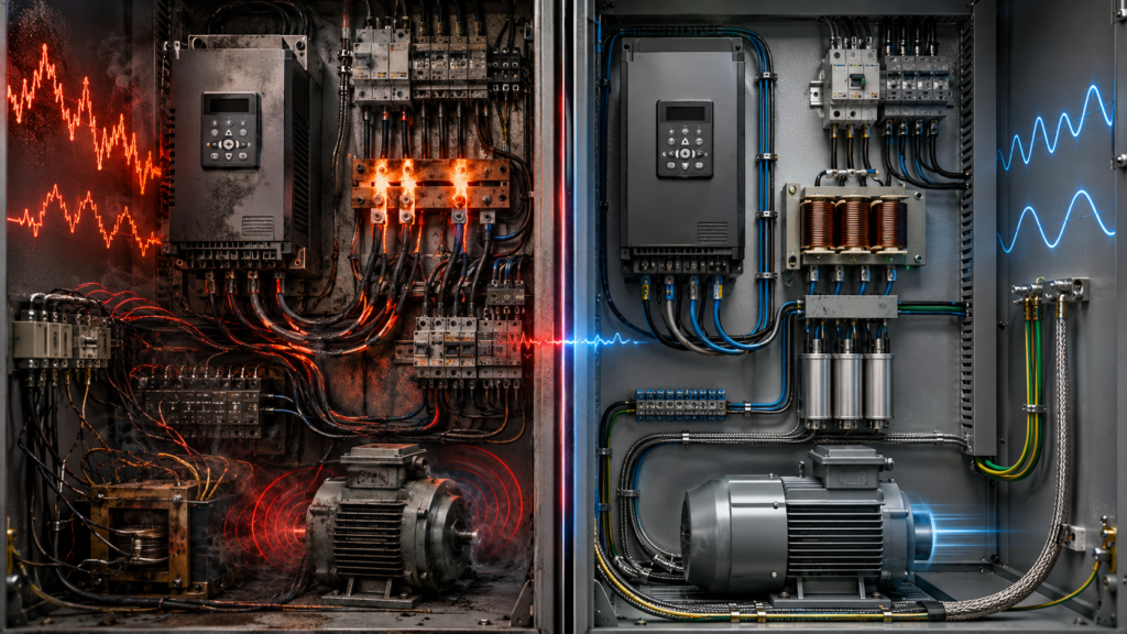
A panel contains several variable-frequency drives. None of them shows a fault, yet the main transformer runs hot, capacitor-bank fuses keep failing and the incomer current seems higher than expected.
The problem may be harmonics.
A VFD does not normally draw a smooth sinusoidal current from the supply. Its input rectifier charges the DC bus in short current pulses near the peaks of the AC waveform. Those pulses contain harmonic currents that travel through the panel, feeder cables and transformer.
Enough harmonic current can cause:
- Additional heating in cables, busbars and transformers
- Higher RMS current through breakers and contactors
- Nuisance trips and fuse operation
- Capacitor-bank overheating or resonance
- Distorted panel voltage
- Incorrect power-factor assumptions
- Unstable operation of other connected equipment
- A need to oversize transformers, generators and conductors
Harmonics do not mean VFDs are bad equipment. Drives can greatly reduce motor starting current, mechanical stress and energy consumption. The electrical distribution system simply needs to be designed for the nonlinear current they draw.
Safety warning: Harmonic measurements are normally performed on live three-phase systems. Use suitably rated instruments, appropriate PPE and approved live-work procedures. Do not open or connect test equipment inside an energised panel unless you are qualified and authorised to do so.
Quick THD Troubleshooting Guide
| Finding | What it suggests | Typical next step |
|---|---|---|
| High THDi at one VFD | Drive input current is heavily distorted | Check whether the drive has an AC/DC choke |
| High THDi but low current at light load | Percentage may look worse than actual harmonic amperes | Review TDD and measurements at normal load |
| High THDv at the panel incomer | Harmonic current is distorting the supply voltage | Analyse transformer and supply impedance |
| Transformer or feeder runs hot | Additional harmonic RMS current and losses | Measure harmonics and review equipment sizing |
| Capacitor fuses fail repeatedly | Harmonic resonance or capacitor overcurrent | Stop replacing fuses and study the network |
| Several drives trip or behave erratically | Distorted or unstable supply voltage | Measure THDv and individual harmonic voltages |
| Strict harmonic target is required | A reactor alone may not be enough | Consider passive filtering, active filtering or low-harmonic drives |
| Motor insulation or bearings are failing | May be PWM output or common-mode issue, not line THD | Investigate motor-side dV/dt and grounding |
What Are Electrical Harmonics?
In a healthy power system, voltage and current should resemble smooth sine waves at the fundamental frequency:
Europe:         50 Hz
North America:  60 Hz
Harmonics are voltage or current components at whole-number multiples of that fundamental frequency.
On a 50 Hz system:
| Harmonic order | Frequency |
|---|---|
| Fundamental | 50 Hz |
| 3rd | 150 Hz |
| 5th | 250 Hz |
| 7th | 350 Hz |
| 11th | 550 Hz |
| 13th | 650 Hz |
A standard three-phase six-pulse VFD typically produces prominent 5th, 7th, 11th and 13th input-current harmonics. The 5th and 7th are normally the most significant lower-order components, particularly when the drive has little input inductance.
The distorted current flows through the impedance of the supply transformer, feeder and busbars. That produces harmonic voltage drops, which distort the voltage available to every other load on the same network. A weaker supply with higher impedance develops more voltage distortion from the same amount of harmonic current.
Why Does a VFD Generate Harmonics?
A conventional VFD generally contains three main sections:
AC supply
→ Diode rectifier
→ DC bus
→ PWM inverter
→ Motor
The inverter controls motor speed by switching the DC-bus voltage rapidly to create a variable-frequency output.
The line-side harmonic problem begins mainly at the input rectifier. Instead of drawing current evenly throughout each AC cycle, the rectifier conducts in pulses while charging the DC-bus capacitors.
A common six-pulse input bridge contains six diodes. It is simple, efficient and inexpensive, but it generates substantial low-order harmonics unless suitable AC or DC inductance is included.
Increasing the input inductance spreads and smooths those current pulses. That is why a drive with a substantial DC choke normally produces less harmonic current than an otherwise similar drive without one. ABB’s laboratory comparison found the lowest current distortion among tested six-pulse drives in the unit with the largest DC inductance.
THDi, THDv and TDD Are Different Measurements
People often say, “The panel has 35% THD.”
That statement is incomplete.
You need to know:
- Current or voltage?
- Measured where?
- At what load?
- Against which reference value?
THDi: Current Total Harmonic Distortion
THDi describes harmonic current relative to the fundamental current.
In simplified form:
THDi =
RMS value of harmonic currents
÷
Fundamental current
× 100%
A higher THDi means the current waveform is further from a pure sine wave. Schneider defines current THD as the relationship between the harmonic content and the fundamental-frequency component.
An individual lightly loaded VFD can show a high THDi percentage even though its actual harmonic current in amperes is relatively small. As fundamental load current falls, the denominator becomes smaller and the percentage can rise. Eaton notes that a large THDi percentage at light load does not necessarily mean the plant has its highest harmonic amperes at that moment.
THDv: Voltage Total Harmonic Distortion
THDv describes harmonic voltage relative to the fundamental voltage.
This measurement is particularly important because distorted voltage affects other loads connected to the same bus.
The VFD produces harmonic current. The electrical network’s impedance turns that current into voltage distortion:
Harmonic current
×
Supply impedance
=
Harmonic voltage
Therefore, the same drive may cause little THDv when connected to a large, stiff transformer but much more THDv when supplied by a small transformer, generator or long feeder.
TDD: Total Demand Distortion
TDD, or Total Demand Distortion, compares harmonic current with the system’s maximum demand load current rather than the instantaneous fundamental current.
This provides a more stable basis when the plant load changes significantly. At full load, current THD and TDD may be similar, but they can differ considerably when the system is lightly loaded.
TDD is especially relevant when checking current-distortion compliance at a facility’s point of common coupling.
What Is the Point of Common Coupling?
IEEE 519 applies harmonic limits at the point of common coupling, normally abbreviated PCC.
The PCC is the interface at which the user’s installation connects to the wider power system or to other customers and loads. IEEE 519-2022 applies steady-state current and voltage distortion limits to the overall installation at that point—not automatically at the input terminals of every individual VFD.
This distinction is important.
A specification saying:
THDi below 5% at the VFD inputis not the same requirement as:
Comply with IEEE 519 at the facility PCCThe first controls one piece of equipment. The second assesses how the complete installation interacts with the supply system.
What Harmonics Do to a Control Panel
1. They Increase RMS Current and Heating
Harmonic currents add to the fundamental current.
Even when harmonic current does not produce useful shaft power, it contributes to total RMS current flowing through:
- Feeder conductors
- Panel busbars
- Breakers
- Fuses
- Disconnects
- Contactors
- Transformers
- Generators
Higher RMS current produces additional resistive loss:
Power loss = I²RA relatively small current increase can create a noticeably larger heat increase because the current is squared.
Danfoss explains that harmonic currents increase heat losses in wiring and transformers and may require a harmonic analysis to prevent overloading transformers, inductors and conductors.
Inside a tightly packed VFD panel, this extra loss adds to the heat already produced by the drives. The result may be:
- Higher enclosure temperature
- Reduced component life
- Drive overtemperature alarms
- Discoloured terminals
- Premature fan failure
- Need for larger cooling equipment
Increasing the air-conditioner size may hide the temperature symptom inside the panel, but it does not remove harmonic losses from the feeder and transformer.
2. Transformers Can Overheat or Become Overloaded
Harmonic current increases transformer copper and stray losses. Higher-frequency components can create additional eddy-current losses that are not represented adequately by considering fundamental current alone.
Where a large proportion of the transformer load consists of ordinary six-pulse converters, the transformer may need to be oversized or specifically evaluated for the nonlinear load. ABB notes that transformer oversizing and harmonic filtering may become necessary when six-pulse converters form a major part of the load.
Typical symptoms include:
- Transformer temperature higher than expected
- Cooling fans running continuously
- Audible noise or vibration
- Available capacity lower than the nameplate kVA suggests
- Voltage waveform distortion on the secondary
- Nuisance trips at loads below the expected kVA limit
Do not replace a hot transformer with a larger one without first understanding the system. A larger transformer usually has lower source impedance, which may reduce THDv, but it can also increase available fault current and require changes to switchgear ratings.
3. Cables and Busbars Run Hotter
A cable may carry the motor-producing fundamental current plus several harmonic-current components.
If cable sizing is based only on the expected kW and a sinusoidal current assumption, the conductor can run hotter than anticipated.
ABB lists cables among the equipment that may overheat due to harmonics.
The risk is greater when:
- Many VFDs share one feeder
- Conductors are grouped tightly
- Ambient panel temperature is high
- The transformer is heavily loaded
- Cable sizes have little spare capacity
- Harmonic mitigation was removed during value engineering
Busbar joints and terminals deserve particular attention. Harmonics do not repair a poorly torqued connection; they simply give it more current to convert into heat.
4. Breakers and Fuses May Operate Unexpectedly
Circuit breakers and fuses respond to RMS current and heating, not only to the current that performs useful work.
Harmonic current can therefore contribute to:
- Thermal breaker tripping
- Fuse heating
- Reduced usable breaker capacity
- Unexpected operation during heavy production
- Misleading comparisons between measured kW and line current
ABB identifies breaker trips and blown fuses among possible harmonic-related symptoms.
Before increasing a breaker rating, verify:
- Actual RMS current
- Cable ampacity
- Breaker thermal condition
- Terminal torque
- Ambient-temperature derating
- Individual harmonic spectrum
- Short-circuit protection requirements
Installing a larger breaker because “the motors only use 80% load” can leave the feeder inadequately protected.
5. Power-Factor Capacitors Can Fail
Capacitors present lower impedance as frequency increases. Harmonic currents can therefore flow heavily into a capacitor bank.
The capacitor may not be generating the harmonics, but it can attract and amplify them.
Possible results include:
- Overheated capacitors
- Bulged cases
- Repeated fuse failures
- Contactor damage
- Excessive capacitor current
- Bus overvoltage
- Resonance with the transformer and network inductance
ABB lists capacitors among components that can overheat due to harmonics. Passive filter guidance also warns that capacitive networks may amplify certain frequencies through resonance.
Do not install an ordinary power-factor-correction bank on a heavily distorted bus without a harmonic study.
A VFD normally presents a displacement power factor close to unity, but its true power factor is reduced by current distortion. Adding ordinary capacitors may correct reactive power that is not the main problem while creating a resonance problem that did not previously exist. Danfoss distinguishes true power factor, which includes harmonics, from displacement power factor, which considers the fundamental component.
Where capacitors are required, a detuned reactor-capacitor system or another engineered solution may be necessary.
6. Voltage Distortion Affects Other Equipment
The VFD draws distorted current. That current produces distorted voltage across the network impedance.
Other equipment on the bus then receives a voltage waveform that is no longer clean.
Potential symptoms include:
- PLC or HMI power-supply faults
- Contactors humming or running hot
- Electronic display flicker
- Lighting problems
- Unreliable metering
- Communication disturbances
- Unexpected trips in sensitive equipment
- Generator voltage-regulator instability
ABB lists flickering displays and lighting, computer failures, false metering and erratic equipment operation among the possible consequences of excessive harmonic distortion.
Harmonics may therefore appear to be an automation problem.
A PLC may restart. A network switch may drop. A drive may report undervoltage or phase-loss alarms. The actual source may be the quality of the panel supply rather than the individual device.
7. Generators and Weak Supplies Are More Sensitive
A generator or small transformer usually has greater source impedance than a strong utility network.
The same harmonic current can therefore create greater voltage distortion.
Problems are particularly likely when:
- A large VFD starts on generator power
- Most of the generator load is nonlinear
- The generator is lightly loaded and voltage regulation is unstable
- Several drives operate from one small transformer
- Long cables separate the source and panel
- The system has little linear load to dilute distortion
The strength of the supply is commonly evaluated using short-circuit capacity relative to the nonlinear load. ABB notes that stronger systems with greater short-circuit capacity and lower impedance produce lower voltage distortion for a given drive load.
8. Meter Readings Can Be Misleading
A basic clamp meter may display RMS current without showing:
- Fundamental current
- Harmonic current
- THDi
- THDv
- TDD
- True power factor
- Individual harmonic orders
A VFD system can show:
Displacement power factor: close to 1.0
True power factor:         considerably lower
The difference comes largely from waveform distortion.
Danfoss explains that true power factor includes harmonic effects and that lower true power factor produces higher RMS current for the same useful kW.
For a meaningful investigation, use a power-quality analyser rather than relying only on an ordinary multimeter or clamp meter.
Line Harmonics Are Not the Same as VFD Output Problems
This distinction prevents expensive mistakes.
Line-side harmonics
These occur between:
Transformer
→ Panel incomer
→ VFD input
They involve lower-frequency current components such as the 5th, 7th, 11th and 13th harmonics.
Solutions include:
- AC line reactor
- DC-link choke
- Passive harmonic filter
- Active harmonic filter
- Multi-pulse rectifier
- Active-front-end or ultra-low-harmonic drive
Motor-side PWM effects
These occur between:
VFD output
→ Motor cable
→ Motor
They include:
- Steep dV/dt
- Reflected-wave overvoltage
- Common-mode current
- Bearing current
- High-frequency EMC emissions
- Motor insulation stress
Motor-side solutions include:
- Output reactor
- dV/dt filter
- Sine-wave filter
- Common-mode filter
- Proper shield termination
- Correct motor cable
- Bearing-protection measures
A dV/dt filter reduces voltage rise time and motor-terminal peak voltage. It is not normally the solution for excessive 5th- and 7th-harmonic current at the panel incomer.
Likewise, fitting an input reactor will not correct a long-motor-cable reflected-wave problem.
How to Measure VFD Harmonics Properly
1. Define the Problem First
Decide what you are trying to answer:
- Is one drive producing excessive current distortion?
- Is the panel transformer overheating?
- Does the plant comply at the PCC?
- Is a capacitor bank resonating?
- Does a new VFD require mitigation?
- Is a generator compatible with the drive load?
The measurement point depends on the question.
2. Measure at More Than One Location
Useful locations include:
Utility or facility PCC
Main transformer secondary
Panel incomer
Individual VFD feeder
Capacitor-bank feeder
Sensitive equipment feeder
Measuring only at one VFD cannot tell you the combined effect of all nonlinear loads at the PCC.
Measuring only at the main incomer cannot identify which drive or load is contributing the dominant harmonic current.
3. Measure All Three Phases
Record:
- Phase-to-phase voltage
- Phase current
- THDv
- THDi
- TDD
- True power factor
- Displacement power factor
- Individual harmonic orders
- Load kW and kVA
- Transformer loading
- Time and machine state
Unbalanced readings can reveal:
- Missing phase conditions
- Unequal VFD loading
- Transformer problems
- Single-phase nonlinear loads
- Incorrect current-transformer placement
- Measurement errors
4. Measure Under Real Operating Conditions
Take measurements during:
- Light production
- Normal production
- Maximum expected load
- Generator operation
- Capacitor-bank switching
- Large motor starting
- Different numbers of drives running
A five-minute measurement during a lunch break may produce a dramatic THDi percentage while missing the real high-current condition later in the shift.
Harmonic amperes generally rise as drive load increases, while percentage distortion can appear worse at partial load. ABB highlights this distinction in its drive-harmonic calculation guidance.
5. Use the Correct Instrument
A proper power-quality analyser should provide:
- True-RMS voltage and current
- Individual harmonic spectrum
- THDv and THDi
- TDD
- Waveform capture
- Trend recording
- Power and power-factor measurements
Current transformers and flexible probes must be oriented correctly and sized for the expected current.
Incorrect probe direction may produce negative power readings. An oversized probe can reduce resolution at low current. A loose voltage lead can create a very convincing fault that exists only inside the test setup.
What THD Level Is Acceptable?
There is no single universal percentage that applies everywhere.
IEEE 519-2022 establishes steady-state voltage and current distortion limits at the user’s PCC. Current limits depend on system strength and the relationship between available short-circuit current and maximum demand load current.
Therefore, these statements are too simplistic:
THD must always be below 5%.A drive with 35% THDi automatically violates IEEE 519.If one drive measures below 5% THDi, the facility complies.A drive may have relatively high current distortion at its terminals while the complete facility still complies at a strong PCC because linear loads and system capacity dilute its effect.
Conversely, several moderate-sized drives on a weak transformer may cause unacceptable voltage distortion even though each drive appears ordinary when examined alone.
Many project specifications deliberately require low harmonic performance at individual drive terminals, commonly 5% or 10% THDi, to simplify the system design. Treat that as an equipment specification, not as the universal definition of IEEE compliance.
How to Reduce VFD Harmonics
Option 1: Use a Drive With a DC Choke
Some VFDs include a DC-link choke as standard. Others have a small choke, optional choke or no meaningful inductance.
A DC choke:
- Smooths rectifier current
- Reduces current peaks
- Lowers low-order harmonics
- Improves true power factor
- Reduces stress on input components
Rockwell describes a DC-link choke as providing a significant harmonic reduction compared with a six-pulse drive without one.
Before adding external equipment, check the selected drive’s technical data. Two drives with the same power rating may produce quite different harmonic performance.
Option 2: Install an AC Line Reactor
A line reactor is installed before the VFD:
Supply
→ Breaker
→ AC reactor
→ VFD
Typical reactor impedance is expressed as a percentage, commonly 3% or 5%.
Benefits include:
- Reduced current peaks
- Some harmonic-current reduction
- Protection against supply transients
- Reduced stress on the rectifier bridge
- Improved behaviour on a stiff supply
The limitation is performance. Eaton reports that a typical 3% reactor may reduce six-pulse-drive current distortion to roughly 35–38%. Increasing to 5% provides only modest additional harmonic improvement while introducing greater voltage drop.
A reactor is therefore a good basic measure, but it will not normally turn a standard six-pulse drive into a 5% THDi solution.
Use a reactor when:
- Basic mitigation is sufficient
- The drive has no built-in choke
- The supply is very stiff
- Rectifier protection is desired
- The harmonic study shows that strict filtering is unnecessary
A reactor may not be enough when:
- The project requires 5% THDi at the drive
- Most transformer load consists of VFDs
- Generator operation is critical
- PCC voltage distortion is already high
- Transformer capacity is limited
Option 3: Use a Passive Harmonic Filter
A passive harmonic filter normally contains inductors and capacitors designed to block or absorb selected harmonic currents.
It is fitted on the VFD input:
Supply
→ Passive harmonic filter
→ VFD
Matched products can provide much greater reduction than a simple line reactor. Danfoss, for example, offers passive filter variants designed for approximately 5% or 10% total harmonic current distortion at full load.
Advantages include:
- Strong reduction of lower-order harmonics
- No active switching electronics
- High efficiency
- Suitable retrofit options
- Lower cost than some active solutions
Limitations include:
- Performance may be load-dependent
- Additional panel space and heat
- Voltage drop
- Capacitor ageing
- Possibility of resonance
- Sensitivity to future network changes
- Need to match the filter and drive correctly
Passive filters can attract harmonics already present on the network. Eaton warns that incorrect application can create resonance, voltage rise or power-factor problems, particularly when the drive is not operating.
Do not select one from motor kilowatts alone. Consider drive input current, supply frequency, voltage, network impedance and loading profile.
Option 4: Use a 12-Pulse or 18-Pulse Drive
Multi-pulse systems use phase-shifted transformer windings and several rectifier bridges.
A 12-pulse system uses two six-pulse bridges supplied with a 30° phase shift. The arrangement causes important harmonic components—particularly the 5th and 7th—to oppose and partially cancel on the transformer primary.
An 18-pulse system uses additional phase-shifted bridges and can provide lower current distortion.
Advantages include:
- Strong lower-order harmonic cancellation
- Mature technology
- No actively switched line converter
- Useful for large individual drives
Disadvantages include:
- Special transformer or autotransformer
- Greater size and weight
- Additional copper and losses
- Need for balanced loading and winding impedance
- Higher initial cost
- Less convenient retrofit installation
Multi-pulse performance depends on balanced supply voltage and closely matched transformer paths. It should not be selected solely from an ideal catalogue percentage.
Option 5: Install an Active Harmonic Filter
An active harmonic filter monitors current and injects an opposing harmonic waveform:
Load harmonic current
+
Opposite filter current
=
Cleaner supply current
This is particularly useful where many nonlinear loads share one bus.
Advantages include:
- One filter can compensate several drives
- Output adapts as load changes
- Retrofit installation is possible
- Can target selected harmonic orders
- Some products also correct reactive power and imbalance
Disadvantages include:
- Higher cost
- Additional heat and panel space
- Current-transformer placement is critical
- Filter must be sized for harmonic amperes, not only load kW
- High-frequency switching considerations
- Interaction with capacitor banks must be studied
ABB describes external active filters as particularly suitable for groups of smaller drives, with the filter generating matching harmonic components in opposite phase.
Rockwell similarly describes active filters as a centralized solution that monitors distortion and injects cancellation current for systems containing multiple drives.
Option 6: Select an Active-Front-End or Ultra-Low-Harmonic Drive
An active-front-end drive replaces the ordinary diode rectifier with a controlled power converter.
Instead of allowing the input current to arrive in large peaks, the active front end regulates it toward a sinusoidal waveform.
Benefits can include:
- Very low THDi
- Near-unity true power factor
- Regenerative energy flow
- Good performance over changing loads
- No separate large passive filter
- Reduced need to oversize upstream equipment
ABB specifies less than 3% THDi for current ultra-low-harmonic drive families such as the ACQ580-31.
Active-front-end solutions can also provide regenerative braking, returning energy to the supply instead of dissipating it in a braking resistor.
Limitations include:
- Higher purchase cost
- More power electronics
- Larger or more complex input filtering
- Additional losses compared with a basic diode bridge
- High-frequency emissions requiring proper filtering
- Greater engineering complexity
Eaton describes active-front-end drives as capable of approximately 2–3% input current distortion while also providing regenerative operation and near-unity power factor.
Option 7: Strengthen or Reconfigure the Electrical System
Sometimes the most practical solution is not attached directly to the drive.
Possible system-level actions include:
- Use a larger or lower-impedance transformer
- Separate large nonlinear loads from sensitive loads
- Divide drives between transformers
- Increase feeder conductor size
- Add a dedicated drive switchboard
- Move capacitor banks
- Use a harmonic-rated transformer
- Review generator sizing
- Reduce unnecessary supply impedance
- Install mitigation centrally at the bus
A larger, stronger supply generally produces less THDv from the same harmonic current. ABB identifies larger transformer capacity, lower transformer impedance and greater supply short-circuit capacity as factors that reduce voltage distortion.
This does not reduce the drive’s THDi by itself. It reduces the amount of voltage distortion produced when that current passes through the network.
Which Harmonic Solution Should You Choose?
| Situation | Practical starting point |
|---|---|
| One small VFD on a large transformer | Built-in DC choke may be sufficient |
| Standard drive without input inductance | Add a 3% line reactor |
| Project requires around 10% THDi | Matched passive harmonic filter |
| Project requires around 5% THDi | Higher-performance passive filter, 18-pulse or active solution |
| Many existing drives share one bus | Active harmonic filter |
| Large drive with regeneration | Active-front-end drive |
| Generator-fed drive installation | Detailed harmonic study and low-harmonic solution |
| Weak transformer with high THDv | Reduce harmonic current and review source impedance |
| Capacitor bank repeatedly fails | Harmonic/resonance study before further replacements |
| Motor cable and bearings are failing | Investigate output filtering—not only input THD |
The best solution depends on:
- Required level at the PCC
- Individual drive specification
- Number and size of drives
- Transformer impedance
- Existing voltage distortion
- Loading profile
- Generator operation
- Available panel space
- Efficiency requirements
- Future expansion
- Retrofit versus new construction
Worked Example: Several Drives on One Transformer
Suppose a panel is supplied by a 400 kVA transformer and contains:
4 × 45 kW VFDs
2 × 22 kW VFDs
PLC and HMI power supplies
One automatic capacitor bank
Several direct-on-line motors
The transformer and panel incomer run hotter after two additional VFDs are installed.
A sensible investigation would be:
- Measure current and voltage distortion at the transformer secondary.
- Record TDD and THDv during maximum production.
- Measure individual drive THDi and check whether each drive has a DC choke.
- Record transformer loading and temperature.
- Measure capacitor-bank current and inspect its reactors and fuses.
- Model the transformer impedance and expected future drive load.
- Compare solutions:
- Reactors on the new drives
- Passive filters on larger drives
- One active filter at the main bus
- Replacing the largest drive with an ultra-low-harmonic model
- Moving some loads to another transformer
Do not jump directly to:
Install a larger main breaker.That may stop the breaker tripping while leaving the transformer, cables and capacitor bank exposed to the same harmonic current.
Common Harmonic-Mitigation Mistakes
Looking only at drive output current
Panel harmonics occur on the VFD input side.
The relevant value is the drive’s actual input current and harmonic spectrum, not merely the motor output current shown on the drive nameplate.
Assuming every line reactor gives 5% THDi
A normal 3% or 5% reactor provides useful reduction, but typical THDi remains much higher than 5%.
Installing an output reactor to fix input THD
An output reactor addresses the VFD-to-motor circuit. It does not normally solve line-side low-order harmonic distortion.
Adding power-factor capacitors without analysis
Capacitors can resonate with the network and attract harmonic current.
Measuring only during light load
THDi percentage may look high while actual harmonic amperes are low. Review TDD, harmonic amperes and normal maximum-load conditions.
Checking compliance at the wrong point
IEEE 519 requirements apply at the PCC, not automatically at each drive terminal.
Selecting a filter without modelling the supply
Passive-filter performance depends on the network, transformer impedance, loading and existing distortion.
Forgetting future drives
A system that is acceptable with three drives may become problematic after six more are installed.
Harmonic planning should include realistic future expansion.
Panel Inspection Checklist
[ ] Number and power of VFDs recorded
[ ] Drive input topology identified
[ ] Built-in AC or DC chokes confirmed
[ ] Transformer kVA and impedance recorded
[ ] Generator operation considered
[ ] Panel incomer RMS current measured
[ ] THDi, THDv and TDD recorded
[ ] Individual harmonic spectrum reviewed
[ ] Measurements taken at normal and maximum load
[ ] True and displacement power factor compared
[ ] Transformer and cable temperatures checked
[ ] Breaker and fuse loading checked
[ ] Capacitor bank inspected
[ ] Existing reactors and filters identified
[ ] PCC clearly defined
[ ] Applicable utility and project limits confirmed
[ ] Future nonlinear loads included
[ ] Motor-side PWM issues separated from line harmonics
[ ] Mitigation options modelled before purchase
[ ] Post-installation measurements planned
Final Thoughts
VFD harmonics begin as distorted input current.
That current then interacts with the electrical system:
VFD harmonic current
→ Additional RMS current
→ Heating in cables and transformers
→ Harmonic voltage drop
→ Distorted voltage across the panel
→ Problems in other connected equipment
A small VFD on a strong transformer may need no special treatment beyond its built-in choke.
A panel in which most of the transformer capacity feeds six-pulse drives may require passive filters, an active filter, multi-pulse equipment or ultra-low-harmonic drives.
Begin by measuring the correct values at the correct locations:
THDi at individual loads
TDD at the PCC
THDv on the shared supply
Actual harmonic amperes
Then select the least complicated solution that meets the real requirement.
Do not install an expensive active filter because one lightly loaded drive shows 60% THDi.
Do not ignore a hot transformer because every VFD says “Ready.”
The percentage needs context. The heat does not.