A drive does not operate in isolation — it feeds a motor through a
cable — and problems in the motor and cable often manifest as drive
faults, so the motor and cable are an essential part of drive
troubleshooting. Moreover, the drive’s PWM output stresses the motor and
cable in particular ways, making them more prone to certain problems
than they would be on a sine-wave supply. Understanding the motor and
cable, and how the drive affects them, completes the diagnostic picture
beyond the drive itself.
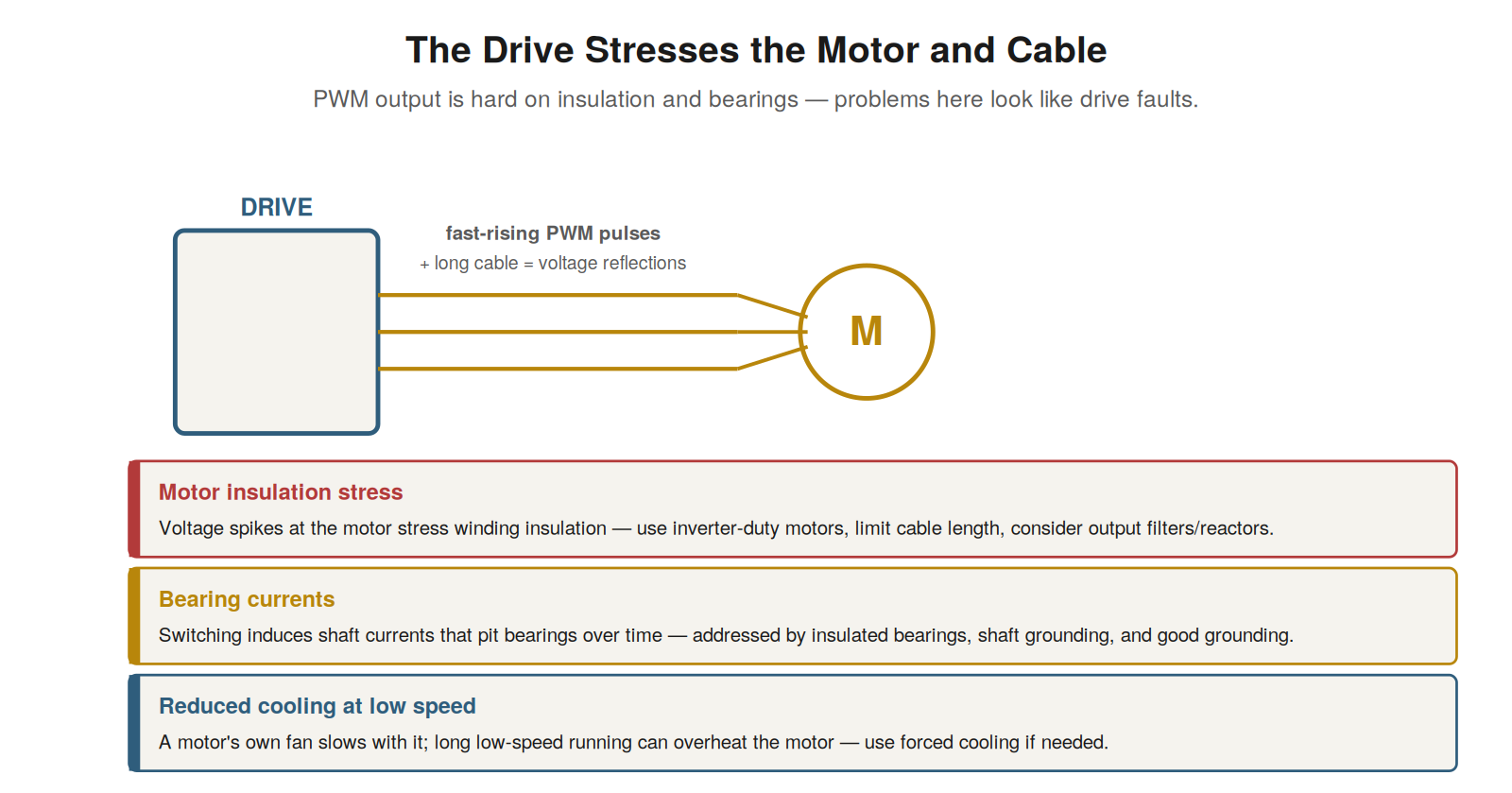
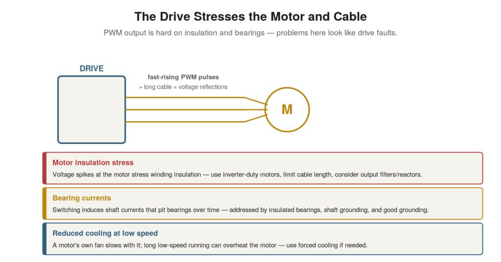
PWM pulses plus long cables cause voltage reflections that stress motor
insulation, switching induces bearing currents, and low-speed running
reduces motor cooling. Problems here often look like drive
faults.
How the drive stresses the motor
The drive’s PWM output stresses the motor in ways a sine-wave supply
does not, and understanding these stresses explains a category of motor
problems in drive systems. The fast-rising voltage pulses of the PWM
output stress the motor’s winding insulation, especially at the first
turns of the winding, and this stress is amplified by long cables, where
the fast pulses cause voltage reflections that can nearly double the
voltage at the motor. This can cause insulation failure over time,
particularly in motors not designed for drive duty. The switching also
induces currents through the motor’s bearings, which can pit and damage
the bearings over time — a phenomenon specific to drive-fed motors. And
running the motor at low speed reduces its self-cooling (the
shaft-driven fan slows with the motor), which can overheat a motor run
slowly for extended periods. Understanding these stresses — insulation
stress from fast pulses and reflections, bearing currents, and reduced
low-speed cooling — explains motor problems that arise specifically in
drive systems. It reinforces that the drive affects the motor beyond
simply powering it: the PWM output stresses the insulation and bearings
and affects cooling, causing motor problems (insulation failures,
bearing damage, overheating) that relate to the drive’s output. These
are addressed by measures like inverter-duty motors, cable length
limits, output filters, insulated bearings, shaft grounding, and forced
cooling, and understanding the stresses explains why drive-fed motors
need these considerations that a sine-supplied motor would not,
connecting the drive’s PWM output to the specific motor stresses it
causes.
Cable considerations
The cable between the drive and motor is more than a simple
connection in a drive system — its type and length matter significantly,
because of the drive’s PWM output. The fast-switched PWM waveform
interacts with the cable: long cables cause voltage reflections that
amplify the voltage at the motor (stressing its insulation), and the
cable’s capacitance can cause extra current and even nuisance
ground-fault trips. So the cable should be the correct type — often
shielded VFD cable designed for the drive’s output — and kept within
length limits, with measures like output reactors or filters for long
cable runs. The cable’s shielding is also important for containing the
noise the switched output generates. Understanding these cable
considerations — the type and length matter because of the PWM output’s
interaction with the cable — is important for drive systems. It
reinforces that the motor cable in a drive system is not a trivial
connection but a component whose type and length affect the motor
stress, the noise, and even the fault behavior (long cables causing
ground-fault trips from capacitance). Understanding that the cable must
be appropriate (correct type, within length limits, shielded) explains
cable-related problems — motor insulation stress, noise, nuisance trips
— and why drive systems specify particular cable types and length limits
that a simple starter would not require, making the cable an important
consideration in both installing and troubleshooting a drive system,
where cable problems can cause motor stress, noise, and faults.
Motor and cable in troubleshooting
Because motor and cable problems often manifest as drive faults,
testing the motor and cable is a key part of drive troubleshooting, and
understanding their role directs the diagnosis appropriately. Many drive
faults — overcurrent, ground fault, overload — can originate in the
motor or cable rather than the drive, so when the diagnosis points
downstream (as the disconnected-motor test can show), testing the motor
and cable localizes the fault. Insulation testing (with the motor and
cable disconnected from the drive, never through it) checks for the
insulation failures that cause ground faults; checking the motor’s
windings and the cable’s continuity and connections checks for other
faults. The motor’s mechanical condition (bearings, load) is relevant to
overload and overcurrent faults. So the motor and cable are a major area
of drive troubleshooting, tested when the fault points downstream of the
drive. Understanding their role — that motor and cable problems cause
drive faults, and are diagnosed by testing them (safely, disconnected
from the drive) — completes the picture of troubleshooting beyond the
drive. It reinforces that a drive fault is not always a drive problem:
the motor and cable it feeds are common sources of faults that the drive
reports, so testing them — insulation, windings, continuity,
connections, and the motor’s mechanical condition — is essential when
the diagnosis points downstream. Understanding the motor and cable as
integral to drive troubleshooting, and how to test them safely, equips
the technician to diagnose the many drive faults that actually originate
in the motor or cable rather than the drive itself.
Inverter-duty motors
Because the drive stresses the motor’s insulation, motors intended
for drive use are often built to withstand it — inverter-duty motors —
and understanding them clarifies a key consideration in drive-motor
systems. The drive’s fast-rising PWM pulses, amplified by cable
reflections, stress the motor’s winding insulation more than a sine-wave
supply would, and an ordinary motor’s insulation may fail prematurely
under this stress. Inverter-duty (or inverter-rated) motors are built
with enhanced insulation designed to withstand the drive’s output, so
they last under the stress that would damage an ordinary motor. Using an
inverter-duty motor on a drive, especially with long cables or demanding
duty, prevents the premature insulation failure that the drive’s output
can cause in an ordinary motor. Understanding inverter-duty motors —
built to withstand the drive’s PWM stress — clarifies why they exist and
when they matter. It reinforces that the motor on a drive should ideally
be inverter-duty, particularly in demanding installations, because the
drive stresses the insulation and an inverter-duty motor is built to
take it. In troubleshooting, a motor suffering insulation failures on a
drive may be an ordinary motor unsuited to the drive’s output, and
understanding inverter-duty motors — their purpose and the stress they
address — explains this and points to using an appropriate motor.
Understanding inverter-duty motors as the answer to the drive’s
insulation stress reinforces matching the motor to the drive’s demanding
output, preventing the insulation failures that an unsuited motor would
suffer.
Scenario: the long cable that stressed the motor
A scenario shows the cable length affecting the motor. A drive drove
a motor through a long cable run, and the motor suffered repeated
winding insulation failures, though it was a decent motor. Understanding
how the drive stresses the motor, especially with long cables, explained
it: the drive’s fast PWM pulses, traveling down the long cable, caused
voltage reflections that nearly doubled the voltage at the motor
terminals, severely stressing the winding insulation and causing the
repeated failures. The long cable amplified the drive’s inherent
insulation stress to a damaging level. The fixes addressed this:
installing an output filter (a reactor or dV/dt filter) to soften the
pulses reaching the motor, and using an inverter-duty motor built to
withstand the stress. These measures reduced the insulation stress,
ending the repeated failures. This scenario shows a long cable
amplifying the drive’s insulation stress into repeated motor failures,
diagnosed through understanding cable reflections. Understanding that
long cables cause voltage reflections amplifying the drive’s insulation
stress explains the repeated failures, and points to the fixes (output
filter, inverter-duty motor). It reinforces that cable length matters in
drive systems, because long cables amplify the insulation stress through
reflections, causing motor insulation failures, addressed by output
filters and inverter-duty motors. The scenario reinforces the cable as
an important consideration: its length, through voltage reflections,
amplified the drive’s insulation stress to a damaging level, causing the
motor failures, which understanding the cable’s role explained and
appropriate measures (filter, inverter-duty motor) resolved.
Output filters and reactors
To address the drive’s stress on the motor and cable, output filters
and reactors are used, and understanding them completes the practical
picture of protecting the motor and cable. The drive’s fast PWM pulses,
amplified by cable reflections, stress the motor insulation, and output
devices mitigate this: an output reactor (an inductor) slows the rise of
the pulses, reducing the reflection and the voltage stress at the motor;
a dV/dt filter or sine-wave filter more thoroughly smooths the output
toward a sine wave, greatly reducing the stress. These devices,
installed at the drive’s output, reduce the insulation stress (and often
the bearing currents and noise too), protecting the motor and cable, and
are particularly used with long cables or sensitive motors.
Understanding output filters and reactors — slowing or smoothing the
pulses to reduce motor stress — completes the means of protecting the
motor and cable from the drive’s output. It reinforces that the drive’s
stress on the motor and cable is mitigated not only by inverter-duty
motors and cable limits but by output filters and reactors that reduce
the stress at its source (the pulses). Understanding output filters and
reactors — the devices that soften or smooth the drive’s output to
protect the motor and cable — equips the technician to address motor and
cable stress, particularly in demanding installations (long cables,
sensitive motors), by reducing the pulse stress that causes insulation
failures, bearing currents, and noise, which these output devices
mitigate at the drive’s output, complementing the inverter-duty motor
and cable-length considerations in protecting the motor and cable from
the drive’s stressful output.
A drive fault is not always a drive problem
A consolidating lesson from the motor and cable is that a drive fault
is not always a drive problem, and recognizing this frames the scope of
drive troubleshooting. Many drive faults — overcurrent, ground fault,
overload — can originate in the motor or cable the drive feeds, not the
drive itself, so the drive reporting a fault does not mean the drive is
faulty. The fault may be in the motor (insulation failure, mechanical
problem), the cable (insulation failure, wrong type or length), or the
load (mechanical problem), with the drive correctly detecting and
reporting the downstream fault. So drive troubleshooting extends beyond
the drive to the motor, cable, and load, and a drive fault should not be
assumed to be a drive problem. Recognizing that a drive fault is not
always a drive problem frames the scope: consider the whole system —
drive, motor, cable, load — not just the drive. It reinforces the
disconnected-motor test and downstream testing, which determine whether
a fault is in the drive or downstream, because the fault may well be in
the motor or cable. Understanding that a drive fault is not always a
drive problem — that the motor, cable, and load are common sources of
faults the drive reports — consolidates the scope of drive
troubleshooting beyond the drive itself, reinforcing that the diagnosis
must consider the whole system and use the splitting tests to determine
where the fault truly lies, rather than assuming a drive-reported fault
is a drive problem, which is often not the case, the fault frequently
originating in the motor or cable the drive feeds and correctly reports
on.