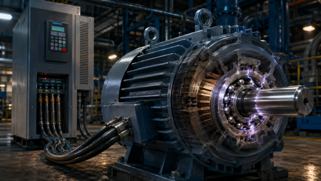
The motor runs smoothly. The current looks normal. The bearings were lubricated correctly, and the machine is not mechanically overloaded.
Yet several months after a variable-frequency drive was installed, the motor begins producing a faint whining noise.
Later, vibration increases. The bearing is replaced, only for the new one to fail unusually early as well. When the old bearing is opened, its raceway has tiny pits or evenly spaced grooves resembling a miniature washboard.
The VFD may be involved.
So, what causes VFD motor bearing damage?
A variable-frequency drive does not supply the motor with a perfectly smooth sine wave. It rapidly switches semiconductor devices on and off to create a pulse-width-modulated output. Those fast voltage transitions can produce common-mode voltage, high-frequency currents and voltage on the motor shaft.
If the shaft voltage becomes high enough to break through the bearing lubricant film, a tiny electrical discharge can jump through the bearing.
One discharge is microscopic.
Thousands or millions of repeated discharges can gradually damage the balls, rollers and raceways until the bearing becomes noisy and eventually fails.
What Does a VFD Actually Send to the Motor?
A variable-frequency drive normally performs three basic electrical steps:
- It converts incoming AC into DC.
- It stores and smooths energy in a DC-link circuit.
- It switches the DC voltage rapidly to create a controlled three-phase output.
The output is produced using pulse-width modulation, usually shortened to PWM.
Instead of generating three perfectly smooth sine-wave voltages, the inverter’s transistors connect each motor phase to different points of the DC bus in a rapid sequence.
A simplified phase output might look more like this:
Full positive DC pulse
↓
Rapid switching
↓
Full negative DC pulse
↓
Rapid switching
↓
Average waveform behaves like AC
The motor’s inductance smooths much of the current, allowing it to produce normal rotating torque. From the motor’s mechanical point of view, the arrangement works extremely well.
Electrically, however, the steep pulse edges create effects that ordinary mains-frequency operation does not produce to the same degree.
Siemens notes that converter-fed motor voltage is generated by PWM and that its steep switching edges can create parasitic currents through motor capacitances, including currents through the bearings.
What Is Common-Mode Voltage?
In an ideal balanced three-phase sine-wave system, the three phase voltages add together in a predictable way.
A PWM inverter behaves differently at each switching instant.
During certain switching states, all three VFD output phases may be driven toward the positive or negative side of the DC bus at the same time. This causes the average voltage of the three phases relative to earth to jump rapidly.
That changing phase-to-earth voltage is called common-mode voltage.
It is called common mode because a similar voltage component appears on all three motor phases relative to ground.
The motor does not use common-mode voltage to produce useful torque.
It is an unwanted side effect of the inverter switching process.
ABB describes the inverter as a common-mode voltage source. The resulting high-frequency current can travel through cable and motor capacitances before returning through the grounding and bonding system.
The useful three-phase current drives the motor.
The common-mode current looks for somewhere else to go.
Motors Contain Unintentional Capacitors
A motor contains conductive parts separated by insulation:
- Stator windings
- Stator core
- Motor frame
- Rotor
- Shaft
- Bearings
- Driven equipment
Whenever two conductive surfaces are separated by insulation, they form some amount of capacitance.
Nobody deliberately installs a capacitor between the stator winding and rotor, but electrically, a small one exists.
A simplified path looks like this:
VFD output winding
↓
Stray capacitance
↓
Rotor
↓
Motor shaft
↓
Bearings
↓
Motor frame
The common-mode voltage pulses couple through these stray capacitances and can charge the rotor and shaft relative to the motor frame.
Fluke explains that capacitive coupling between a motor’s stator and rotor can create shaft voltage. With rapidly switching VFD waveforms, shaft-to-frame voltage can become considerably higher than it is with ordinary sine-wave mains operation.
The motor shaft may therefore carry a measurable voltage even though nobody has connected a wire directly to it.
What Is Shaft Voltage?
Shaft voltage is the electrical potential difference between the rotating motor shaft and another part of the system, usually the motor frame or earth.
Several mechanisms can produce it, including:
- Capacitive coupling from stator windings
- Common-mode voltage
- High-frequency circulating currents
- Magnetic asymmetry
- Grounding-potential differences
- Current returning through driven equipment
A small shaft voltage does not automatically mean the bearing is being destroyed.
Damage occurs when the voltage and available discharge energy are sufficient to break through the lubricant film or create a harmful circulating-current path.
The exact risk depends on the complete drive system:
- VFD design
- Motor construction
- Motor size
- Cable length
- Switching frequency
- Grounding
- Cable shielding
- Bearing type
- Lubricant
- Shaft speed
- Temperature
- Driven equipment
This is why two apparently similar VFD motors can have very different bearing lifetimes.
The motor is only one part of the electrical circuit.
Bearing Grease Temporarily Acts as an Insulator
Inside a healthy rolling bearing, the rolling elements are separated from the raceways by a very thin lubricant film during operation.
That film reduces friction and metal-to-metal contact.
Electrically, the lubricant can also behave as an insulating layer.
This makes the bearing resemble a tiny capacitor:
Shaft and inner race
↓
Lubricant film
↓
Rolling element
↓
Lubricant film
↓
Outer race and motor frame
As common-mode voltage couples onto the shaft, electrical charge can build across that insulating film.
At first, little current flows through the bearing.
Then the voltage reaches the lubricant film’s breakdown level.
The insulation fails for an extremely short moment, and the stored charge discharges through a tiny contact point inside the bearing.
Electrical Discharge Through the Bearing
The discharge is similar in principle to a microscopic spark.
Current jumps through the lubricant film between:
- Ball and race
- Roller and race
- Inner and outer bearing surfaces
The event occurs extremely quickly.
The current density at the discharge point can be high enough to melt a microscopic area of metal. The metal then cools and solidifies again, leaving a tiny crater.
This is sometimes described as electrical discharge machining, or EDM, because the process resembles the controlled spark erosion used in EDM manufacturing.
In a motor bearing, however, it is neither controlled nor useful.
Fluke states that shaft-voltage discharges can break through the insulating properties of bearing grease and create pitting, fusion craters and fluting, eventually leading to premature bearing failure.
One tiny crater would probably never be noticed.
Repeated continually, the damage accumulates.
How Microscopic Pits Become a Failed Bearing
The initial damage may appear as tiny grey or frosted areas on the bearing surface.
As the motor continues running:
- More electrical discharges create additional pits.
- Rolling elements repeatedly pass over the damaged areas.
- Surface roughness increases.
- Lubricant becomes contaminated with metal particles.
- Mechanical vibration grows.
- Damage spreads across the raceway.
- The bearing becomes noisy and eventually fails.
The failure is both electrical and mechanical.
Electricity creates the first surface damage. Normal rolling forces then make it worse.
Possible visual signs include:
- Frosted raceways
- Grey discolouration
- Microscopic pitting
- Burn marks
- Craters
- Fluting
- Damaged lubricant
- Darkened grease
A bearing can look acceptable from a distance while showing clear electrical damage under magnification.
What Is Bearing Fluting?
Fluting is a pattern of parallel grooves across a bearing raceway.
The grooves are often evenly spaced and may resemble:
- A washboard
- Corduroy
- Fine machining marks
- Repeated bands across the race
Fluting is not necessarily formed by one enormous arc.
It develops through repeated electrical discharges combined with vibration and repeated rolling contact. The bearing surface becomes damaged in a pattern related to the machine’s mechanical and electrical behaviour.
Symptoms may include:
- Rising high-frequency vibration
- Whining
- Growling
- Increasing bearing temperature
- Shortened lubricant life
- Repeated bearing replacement
A motor may continue operating for a considerable time after damage begins.
By the time the sound becomes obvious, the bearing race may already be badly marked.
Not Every VFD Motor Develops Bearing Damage
Installing a VFD does not guarantee that the bearings will fail.
Many VFD-driven motors operate for years without electrically related bearing problems.
ABB notes that bearing currents account for only a small proportion of overall bearing failures. Mechanical overloading, incorrect lubrication, contamination, moisture and excessive radial or axial forces remain common causes.
Before blaming the drive, also investigate:
- Misalignment
- Incorrect belt tension
- Excessive coupling load
- Poor lubrication
- Wrong grease
- Contamination
- Seal damage
- Bent shafts
- Soft foot
- Mechanical resonance
- Excessive vibration
- Improper bearing installation
A fluted raceway strongly suggests electrical involvement.
A hot, damaged bearing by itself does not prove it.
Different Types of VFD Bearing Current
“Bearing current” is not one single phenomenon.
Several current paths can occur, and the correct solution depends on which one is present.
Capacitive discharge current
Common-mode voltage charges the shaft through motor capacitance.
When the lubricant film breaks down, charge discharges through the bearing.
This is the classic EDM-type failure often discussed in smaller low-voltage motors.
High-frequency circulating bearing current
In larger motors, high-frequency magnetic flux around the shaft can create voltage from one end of the shaft to the other.
Current may then circulate through:
Drive-end bearing
↓
Motor shaft
↓
Non-drive-end bearing
↓
Motor frame
This creates a loop through both bearings.
Shaft-grounding current
The shaft may be connected to ground through the driven machine, gearbox, coupling or another conductive path.
Current may pass through one motor bearing, along the shaft and into the grounded load.
ABB identifies both high-frequency circulating currents and shaft-grounding currents as important current paths in variable-speed drive systems.
This distinction explains why there is no single bearing-protection device suitable for every installation.
Can the Current Damage the Gearbox Too?
Yes.
The discharge path may not end at the motor.
If the motor shaft is connected through a conductive coupling to a gearbox, pump, fan or other machine, common-mode current may travel through bearings outside the motor.
Possible paths include:
Motor shaft
↓
Coupling
↓
Gearbox shaft
↓
Gearbox bearing
↓
Machine frame
Or:
Motor bearing
↓
Motor shaft
↓
Driven-equipment bearing
↓
Ground
ABB warns that incorrect motor cabling can increase voltages affecting the motor, gearbox and driven-machine bearings, shortening their service life.
Replacing only the motor bearing may therefore leave the real current path untouched.
The new bearing fails, everyone blames the bearing manufacturer, and the electrical current quietly continues using the same route.
Why PWM Switching Speed Matters
VFD transistors switch very quickly.
The rate at which voltage changes is described as:
dV/dtA steep voltage edge contains high-frequency energy.
At high frequencies, capacitances that seem insignificant at 50 or 60 Hz can carry meaningful current.
Capacitive current rises with:
- Greater capacitance
- Higher switching frequency
- Faster voltage change
- Higher voltage magnitude
This is why a few nanofarads of stray motor capacitance can matter in a VFD system even though it would appear almost irrelevant during ordinary mains operation.
Siemens explains that steep PWM voltage edges create parasitic currents because of winding capacitance, and that part of this current may flow through motor bearings.
A VFD does not need enormous capacitance to produce trouble.
It only needs to charge and discharge a small capacitance very quickly, thousands of times per second.
Does a Higher Carrier Frequency Increase the Risk?
Increasing VFD carrier frequency can make the motor sound quieter because the switching noise moves higher in frequency.
It also increases the number of switching events.
Depending on the drive, motor and installation, a higher carrier frequency may increase:
- Common-mode current
- Motor heating
- Cable current
- Switching losses
- Bearing-discharge frequency
Reducing carrier frequency can sometimes help, but it is not a universal repair.
It may also cause:
- More audible motor noise
- Different motor heating
- Reduced drive output capability
- Changes in control performance
Drive parameters should follow the motor and VFD manufacturer’s recommendations.
Randomly changing the carrier frequency until the bearing stops complaining is not a complete engineering strategy.
Why Motor-Cable Length Matters
A VFD motor cable has capacitance between:
- Phase conductors
- Cable shield
- Protective earth
- Surrounding metalwork
Longer cable generally means greater total capacitance.
Each PWM transition must charge and discharge that capacitance, increasing high-frequency current.
Long cables can also produce voltage reflections at the motor terminals. Those reflected pulses may increase motor insulation stress and complicate the high-frequency behaviour of the entire installation.
ABB lists proper motor cabling and grounding among the primary methods for reducing common-mode and bearing-current problems. It also recommends filters in certain applications involving long motor leads or elevated voltage stress.
The cable is not merely a long piece of copper connecting the drive to the motor.
At PWM frequencies, it becomes an electrical component.
Insulated Bearings
An insulated bearing interrupts an electrical path between the shaft and motor frame.
The insulation may be provided by:
- A ceramic-coated outer ring
- A ceramic-coated inner ring
- Ceramic rolling elements
- Hybrid-bearing construction
- Insulated bearing housings
For high-frequency circulating current, a common arrangement is to insulate the non-drive-end bearing.
That breaks the current loop through both ends of the motor.
ABB identifies an insulated non-drive-end bearing as an effective option for preventing circulating bearing current in many larger-motor applications.
However, insulated bearings must be selected as part of the complete current-control strategy.
Blocking one path can force current to find another.
Why Insulating One Bearing Can Help
Consider a circulating-current path:
Drive-end bearing
↓
Shaft
↓
Non-drive-end bearing
↓
Motor frame
If the non-drive-end bearing is insulated, that loop is interrupted.
Current cannot easily circulate through both motor bearings.
This can protect the raceways from high-frequency circulating current.
But the shaft may still develop common-mode voltage.
If the shaft is connected to grounded driven equipment, the current may instead flow through:
- The drive-end bearing
- The coupling
- Gearbox bearings
- Pump bearings
- Encoder bearings
The electrical path must be considered beyond the motor housing.
Current is quite willing to accept a scenic route.
Why Insulating Both Bearings Is Not Always Enough
Insulating both bearings can prevent current from flowing through the motor bearings.
It may also allow shaft voltage to rise because the shaft now has no intended discharge path.
If the shaft connects to a grounded load, the current may discharge through the driven machinery instead.
For certain systems, both bearings are insulated intentionally. In others, one insulated bearing is combined with a shaft-grounding device.
ABB lists insulation at both bearing ends as one available solution but stresses that bearing-current mitigation is application-specific rather than one-size-fits-all.
More insulation is not automatically more protection.
Sometimes it simply moves the damage twenty centimetres down the shaft.
What Is a Shaft-Grounding Ring?
A shaft-grounding ring provides a controlled, low-impedance connection between the rotating shaft and the grounded motor frame.
It typically contains conductive fibres or brushes that maintain contact with the shaft as it rotates.
The intended path becomes:
Motor shaft
↓
Grounding ring or brush
↓
Motor frame
↓
Protective grounding system
The grounding ring gives high-frequency current an easier route than passing through the bearing lubricant.
ABB describes a shaft-grounding brush as a method of directing current to ground through the brush instead of through the bearing.
The bearing is no longer expected to act as an improvised spark gap.
That tends to improve its mood considerably.
Shaft-Grounding Rings Need Proper Installation
A grounding ring works only when it has a reliable electrical connection.
Important details include:
- Clean shaft surface
- Correct mounting position
- Good bonding to the motor frame
- Protection from oil and contamination
- Correct conductive contact
- Proper mechanical alignment
- Regular inspection
Paint, rust, grease or dirt between the ring housing and motor frame can increase impedance.
The shaft surface may also develop coatings that reduce contact.
Some installations require the shaft to be cleaned or treated according to the grounding-device manufacturer’s instructions.
Installing a grounding ring badly is rather like installing a protective-earth wire onto a painted terminal and hoping the colour will carry the current.
Ring, Brush or Carbon Contact?
Several shaft-grounding designs exist:
- Conductive microfiber rings
- Carbon brushes
- Metal brushes
- Internal grounding devices
- Externally mounted devices
The best option depends on:
- Shaft speed
- Motor size
- Environment
- Dust
- Moisture
- Maintenance access
- Current type
- Bearing arrangement
Carbon brushes can provide a robust current path but may require wear inspection.
Fibre rings provide many contact points but still need correct installation and cleanliness.
There is no universally superior design for every motor.
The current does not care which product brochure looked nicest.
It follows impedance.
Combining a Grounding Ring With an Insulated Bearing
A commonly used arrangement is:
Drive end:
Shaft-grounding device

Non-drive end:
Insulated bearing
The grounding device gives shaft current a controlled route to the frame.
The insulated bearing interrupts a circulating-current path through the opposite end.
This can address more than one bearing-current mechanism.
However, the exact arrangement depends on:
- Motor frame size
- Bearing-current type
- Driven load
- Coupling
- Gearbox
- Motor manufacturer
- Drive manufacturer
- Installation grounding
ABB emphasizes that the chosen mitigation must match the particular motor and drive system.
Copying the arrangement from another machine may work.
It may also protect the wrong bearing from the wrong current.
Correct Grounding Is the First Line of Defence
Before adding special bearings and rings, inspect the basic drive installation.
High-frequency current needs a low-impedance route back to the VFD.
A conductor may have low resistance at 50 Hz but relatively high impedance at PWM switching frequencies because of its:
- Length
- Shape
- Inductance
- Routing
- Connection method
ABB states that correct cabling and grounding strongly reduce the motor shaft and frame voltages that lead to high-frequency bearing currents.
A thick but long grounding wire with a curled route may be less effective at high frequency than a short, wide bonding connection.
The current is moving quickly.
The grounding system must be designed accordingly.
Use a Symmetrical Shielded Motor Cable
Drive manufacturers commonly recommend symmetrical shielded motor cable.
A suitable cable may contain:
- Three symmetrically arranged phase conductors
- A concentric shield
- Symmetrical protective-earth conductors
- Proper insulation for PWM voltage stress
Symmetry helps keep electromagnetic conditions around the three phases balanced.
The shield provides a controlled route for high-frequency common-mode current.
ABB recommends symmetrical shielded motor cables and notes that proper cable construction reduces motor-frame voltage, with the effect becoming especially important at higher motor currents.
Ordinary unshielded installation cable may operate the motor.
That does not mean it provides the best high-frequency behaviour for a VFD system.
Ground the Shield at Both Ends
For VFD motor cables, the shield is generally connected at both the drive and motor ends according to the manufacturer’s instructions.
This allows high-frequency current to return through a controlled path.
ABB recommends grounding the cable shield at the motor end and using a full 360-degree connection at the motor terminal-box entry to minimize high-frequency interference.
The shield should not normally be reduced to one long, thin twisted pigtail.
A pigtail adds inductance.
At mains frequency, it may appear adequately connected. At high PWM frequencies, its impedance may greatly reduce the shield’s effectiveness.
A proper 360-degree cable gland or shield clamp maintains contact around the cable circumference.
Why a Pigtail Shield Connection Is Poor at High Frequency
A long wire has inductance.
When current changes rapidly, voltage develops across that inductance:
Faster current change
+
Greater inductance
=
Greater high-frequency voltage drop
A narrow pigtail may therefore prevent common-mode current from returning efficiently through the intended cable shield.
Instead, current may travel through:
- Motor bearings
- Machine frames
- Building steel
- Encoder cables
- Communication screens
- Other grounding conductors
A good high-frequency connection should be:
- Short
- Wide
- Direct
- Mechanically secure
- Free from paint and corrosion
The shortest route is usually best.
High-frequency current has little patience for decorative wiring.
Bond the Motor and Driven Equipment Properly
The motor frame, VFD enclosure and driven machinery should form a well-bonded equipotential system.
Poor bonding can create voltage differences between:
- Motor frame and gearbox
- Drive cabinet and motor
- Pump skid and building steel
- Coupled machine sections
Those differences may drive current through bearings or couplings.
ABB recommends short grounding connections and good electrical bonding of cable trays, enclosures and grounding structures to reduce high-frequency impedance.
This does not mean adding random parallel earth wires without a design.
Grounding and bonding should follow:
- Drive-manufacturer instructions
- Motor-manufacturer instructions
- Applicable electrical standards
- Local electrical regulations
- EMC requirements
- Machine-safety requirements
Protective earthing keeps people safe.
High-frequency bonding helps the drive system behave properly.
Both matter.
Keep Unshielded Cable Sections Short
At the motor terminal box and VFD output terminals, part of the cable may need to be stripped.
The exposed phase conductors no longer have the full surrounding cable shield.
Long unshielded tails increase the area from which high-frequency fields can escape and reduce the effectiveness of the return path.
ABB advises keeping the unshielded part of the motor cable as short as possible at both the drive and motor ends.
Do not remove half a metre of shield merely because it makes the terminals easier to reach.
Neat routing is useful.
Removing the EMC design from the cable is less useful.
Filters Can Reduce Electrical Stress
Depending on the motor, cable and drive, additional output filtering may be used.
Possible options include:
dV/dt filter
Reduces the rate at which motor-terminal voltage changes.
It is often used to reduce motor insulation stress and can also influence high-frequency current.
Common-mode filter
Specifically reduces common-mode current and voltage effects.
ABB lists common-mode filtering as an option for reducing the risk of bearing currents in suitable larger-motor applications.
Sine-wave filter
Converts the PWM output into a waveform much closer to a sine wave.
It can significantly reduce motor-terminal pulse stress, noise and certain common-mode effects, but it adds cost, size and power loss.
Filters must be compatible with:
- VFD model
- Motor current
- Output frequency
- Switching frequency
- Cable length
- Control method
Do not install a random reactor and assume every high-frequency problem has now signed a peace treaty.
Can Changing the VFD Solve the Problem?
Different VFD topologies and control methods can produce different common-mode behaviour.
Some drives include:
- Common-mode filtering
- Alternative PWM patterns
- Reduced-common-mode switching strategies
- Adjustable carrier frequency
- Motor-bearing protection recommendations
However, replacing the drive alone may not solve poor grounding, cable shielding or bonding.
The drive, cable, motor and load form one high-frequency system.
A better VFD connected through an unsuitable cable to a poorly bonded motor can still produce an unwanted current path.
Start with the installation instructions for the specific VFD and motor combination.
Generic advice is useful.
The manufacturer’s application data is better.
How Is Shaft Voltage Measured?
Shaft-voltage measurement is not a normal multimeter test.
The damaging events may have:
- Very fast rise times
- Short durations
- High repetition rates
- High-frequency content
A conventional handheld multimeter may average the signal and completely miss the discharge spikes.
Testing generally requires:
- A shaft-voltage probe
- Conductive brush contact
- High-bandwidth oscilloscope or motor-drive analyzer
- Proper frame reference
- Qualified personnel
- Safe access to the rotating shaft
Fluke notes that shaft-voltage spikes may occur within extremely short time periods and uses a dedicated conductive shaft probe with high-speed measuring equipment to capture discharge events.
Do not press an ordinary pointed multimeter probe against a spinning shaft.
The measurement should not create a new bearing injury—this time involving the technician.
What Does a Discharge Waveform Look Like?
A shaft-voltage waveform may rise gradually or in steps relative to the motor frame.
When the lubricant film breaks down, the voltage suddenly collapses.
A simplified waveform resembles:
Shaft voltage rises
       /
      /
     /
    /
   │ Sudden discharge
   │
___│________________
Repeated sharp collapses suggest electrical discharges through the bearing or another shaft path.
Measurement should ideally compare:
- Voltage amplitude
- Discharge frequency
- Rise time
- Operating speed
- Motor temperature
- VFD carrier frequency
- Load condition
The measurement can then be repeated after changes to:
- Cable bonding
- Grounding
- Drive settings
- Shaft-grounding devices
- Filters
- Bearing insulation
This verifies whether the mitigation actually reduced discharge activity.
Warning Signs of VFD Bearing Damage
Possible symptoms include:
- New high-pitched bearing noise
- Growling or whining
- Rising vibration
- Increasing bearing temperature
- Repeated bearing failures
- Grey or frosted raceways
- Pitting
- Fluting
- Darkened or contaminated lubricant
- Bearing failure soon after VFD conversion
- Similar damage in a gearbox or driven machine
These symptoms do not prove electrical discharge by themselves.
A proper investigation should include:
- Bearing inspection
- Vibration analysis
- Shaft-voltage measurement
- Grounding inspection
- Cable-shield inspection
- Mechanical alignment check
- Lubrication review
- Load measurement
- Drive-parameter review
The fastest explanation is not always the correct one.
Sometimes the VFD is guilty.
Sometimes the bearing was simply installed with a hammer.
Common VFD Bearing-Damage Myths
“VFDs send DC through the bearing”
Not normally.
The main problem is high-frequency voltage and current produced by PWM switching and common-mode coupling, not ordinary steady DC from the drive’s internal bus.
“Every VFD motor needs an insulated bearing”
No.
The requirement depends on motor size, construction, cable, grounding and current mechanism.
“A shaft-grounding ring fixes every bearing-current problem”
No.
It provides an alternative shaft-current path, but high-frequency circulating current may also require bearing insulation, filtering or improved cabling.
“Insulating both bearings guarantees complete protection”
Not necessarily.
Current may be redirected through the coupling, gearbox or driven-equipment bearings.
“The normal protective-earth wire solves everything”
Protective earthing is essential, but high-frequency current also depends on connection length, inductance, cable symmetry, shield termination and bonding.
“A cable shield should be grounded at only one end”
That rule may apply to certain low-frequency signal cables.
VFD motor-cable shields are generally terminated at both ends with low-impedance, 360-degree connections according to the drive manufacturer’s instructions.
“A low multimeter shaft-voltage reading means there are no discharges”
Not necessarily.
A standard meter may be too slow to capture extremely fast bearing-discharge pulses.
“All early bearing failures on VFD motors are electrical”
No.
Mechanical load, lubrication, contamination, alignment and installation remain common causes.
A Practical Prevention Checklist
For a VFD-driven motor, check that:
- The motor is approved or suitable for inverter duty.
- The VFD and motor are correctly matched.
- A symmetrical shielded motor cable is used where specified.
- The cable shield is terminated properly at both ends.
- Shield connections provide 360-degree contact.
- Unshielded cable tails are kept short.
- The motor frame is bonded correctly.
- The driven machine and gearbox are bonded.
- Protective-earth conductors are correctly sized.
- Motor-cable length remains within drive limits.
- Carrier-frequency settings follow manufacturer guidance.
- Output filters are fitted where required.
- Insulated bearings are installed in the correct position.
- Shaft-grounding rings or brushes have clean contact.
- Grounding devices are inspected during maintenance.
- Bearing noise and vibration are trended.
- Repeated bearing failures are investigated electrically and mechanically.
Disconnect, lock out and verify isolation before installing grounding rings, modifying cable connections or inspecting motor terminals.
A stopped VFD is not necessarily electrically discharged. Its DC-link capacitors may retain dangerous voltage after supply removal.
Follow the stated discharge time and verify safely before beginning work.
The Practical Answer
So, why does VFD motor bearing damage occur?
A VFD creates motor voltage using rapid PWM switching.
Those switching pulses produce common-mode voltage and high-frequency current. Through the motor’s unavoidable internal capacitances, part of that voltage can appear on the rotor and shaft.
The lubricant film inside a bearing temporarily insulates the shaft from the motor frame.
When the shaft voltage becomes high enough, the lubricant film breaks down and a tiny electrical discharge passes through the bearing. Repeated discharges create microscopic craters, frosting and eventually fluting across the raceways.
The most effective protection depends on the current path, but common solutions include:
- Correct symmetrical motor cable
- Proper 360-degree shield termination
- Short, low-impedance grounding connections
- Good bonding between the drive, motor and machine
- Insulated bearings
- Shaft-grounding rings or brushes
- Common-mode, dV/dt or sine-wave filters
No single device solves every installation.
An insulated bearing may interrupt one current loop while sending current through a gearbox. A grounding ring may divert shaft discharge current but not eliminate every circulating-current mechanism.
The entire system must be considered:
VFD
+
Motor cable
+
Grounding
+
Motor
+
Coupling
+
Driven machine
The bearing damage appears in one small component.
The cause may be distributed through the whole drive installation.