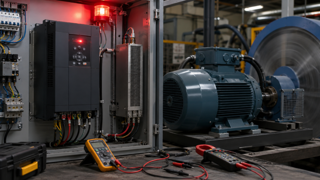
The motor accelerates and runs normally. The fault appears only when the VFD tries to slow it down.
Depending on the drive, the display may show:
- DC bus overvoltage
- DC link overvoltage
- Overvoltage during deceleration
- F30002 on certain Siemens SINAMICS drives
- A manufacturer-specific overvoltage alarm code
This usually does not mean the motor is receiving too much output voltage. It means the voltage inside the VFD’s DC link has risen above its safe limit.
The most common cause is simple: the motor and machine are returning more energy to the drive than it can absorb or dissipate.
Why Does DC Bus Voltage Rise During Deceleration?
While driving the machine, the motor converts electrical energy into mechanical motion.
During rapid deceleration, the situation reverses. The rotating load drives the motor, causing it to operate as a generator. Energy flows from the motor back into the VFD’s DC link.
If that energy cannot be removed quickly enough, the DC voltage rises until the drive trips to protect its power electronics. Siemens describes this exact process: a load-driven induction motor regenerates electrical power into the inverter, raising the DC-link voltage until an overvoltage fault occurs.
Loads that commonly create high regenerative energy include:
- Large fans
- Centrifuges
- Flywheels
- High-speed spindles
- Conveyors carrying heavy products
- Hoists and lowering applications
- Unbalanced vertical loads
- Machines with large rotating drums
Step 1: Confirm That the Fault Occurs During Braking
Check the VFD fault history and note exactly when the trip occurs.
Does it happen:
- Immediately after the stop command?
- Near the end of the deceleration ramp?
- Only when stopping from maximum speed?
- Only with material in the machine?
- During lowering or overhauling operation?
- When several drives decelerate together?
Monitor or trace:
- DC bus voltage
- Output frequency
- Motor speed
- Motor current
- Torque
- Frequency reference
- Braking-chopper status
A DC-link voltage that rises as output frequency falls strongly suggests regenerative braking rather than an ordinary supply-side problem.
Step 2: Increase the Deceleration Time
The easiest test is to make the deceleration ramp longer.
If the drive currently stops in two seconds, try five or ten seconds—provided the machine can safely take longer to stop.
A longer ramp spreads the returned energy over more time, reducing the rate at which the DC bus charges. Danfoss officially lists extending the ramp time as a first corrective action for a DC-overvoltage trip.
If the fault disappears, the original ramp was too aggressive for the load and available braking system.
Do not automatically leave the ramp extremely long. Check:
- Required production cycle
- Machine stopping distance
- Safety requirements
- Process stability
- Mechanical brake timing
An emergency stop must follow the machine’s validated safety design. Do not alter safety stopping behaviour simply to remove a drive fault.
Step 3: Enable Overvoltage Control
Many VFDs include a DC-bus or overvoltage controller.
When the DC-link voltage becomes too high, this function temporarily reduces regenerative braking torque or extends the deceleration ramp. The machine takes longer to stop, but the drive avoids tripping where the application permits it.
On Siemens SINAMICS drives, this may be called the Vdc-max controller. Siemens states that it reduces braking torque when the DC-link voltage reaches the configured threshold.
Other manufacturers use names such as:
- Overvoltage control
- Stall prevention during deceleration
- Automatic ramp extension
- Regeneration avoidance
- DC-bus regulation
Danfoss describes overvoltage control as automatically extending the ramp-down time when necessary to limit DC-link voltage.
Check whether the function is:
- Supported by the drive
- Enabled
- Correctly configured
- Compatible with the motor-control mode
- Acceptable for the process
It may not be suitable where a precise stopping time is mandatory.
Step 4: Check the Configured Supply Voltage
Some drives use the entered mains voltage when calculating DC-bus control thresholds.
If the parameter is incorrect, the overvoltage controller may respond too late or behave incorrectly.
For Siemens SINAMICS equipment, Siemens specifically advises setting the device supply-voltage parameter correctly when configuring the Vdc-max controller.
Compare:
- Actual line-to-line voltage
- Drive nameplate voltage
- Configured mains voltage
- Permitted supply range
Do not increase an overvoltage threshold simply to prevent the trip. The threshold protects the VFD’s DC capacitors and power semiconductors.
Step 5: Measure the Incoming Supply Voltage
A high mains supply raises the VFD’s normal DC-bus voltage before braking even begins.
That leaves less room for regenerative energy during deceleration.
Measure all incoming phase-to-phase voltages:
- L1–L2
- L2–L3
- L3–L1
Check them while the machine is running and during the period when the fault occurs.
Possible supply-side causes include:
- Transformer tap set too high
- Utility voltage near the upper tolerance
- Generator regulation problems
- Incorrect drive voltage class
- Sudden supply disturbances
- Other regenerative equipment raising a shared bus
A drive that normally operates close to its upper DC-voltage limit may trip from a smaller amount of returned energy.
Step 6: Check Whether a Braking Resistor Is Required
A standard non-regenerative VFD cannot normally return braking energy to the AC supply.
A braking chopper and resistor provide another path. The chopper switches the DC-link energy into the resistor, where it is converted into heat. Siemens describes braking resistors as the component used to reduce energy returned to the DC link during regenerative operation.
A braking resistor may be necessary when:
- The required stop time is short
- The load has high inertia
- Stops occur frequently
- The machine has a vertical or overhauling load
- Overvoltage control makes the stop too slow
- The internal braking capacity is insufficient
Some drives include a braking chopper. Others require an optional braking module, and some cannot use a resistor at all.
Check the exact drive model before ordering parts.
Step 7: Inspect the Braking Resistor Circuit
A fitted resistor does not prove that the braking circuit is working.
After isolation and full DC-bus discharge, inspect:
- Resistor wiring
- Braking terminals
- Cable continuity
- Terminal tightness
- Resistor resistance
- Braking-module enable
- Thermal-switch circuit
- Chopper diagnostics
- Burned or damaged components
A fault in the resistor braking circuit can prevent fast deceleration and cause an overvoltage trip. ABB lists missing enable signals, resistor or cable faults, and overheated braking equipment among problems that disable effective braking.
Do not touch a braking resistor immediately after operation. It may reach a dangerously high temperature.
Step 8: Verify the Resistor Resistance
A braking resistor must have the correct resistance for the VFD.
Resistance Too High
The braking current is too low, so the resistor cannot absorb energy quickly enough. The DC bus may continue rising until the drive trips.
Resistance Too Low
The braking chopper may be overloaded or damaged by excessive current.
Use only a resistance value permitted by the drive manufacturer. Danfoss warns that selecting a resistor with too high an ohmic value can reduce braking power and cause the drive to trip.
Do not install a lower-resistance unit simply because you want stronger braking.
Step 9: Check the Resistor’s Power and Duty Cycle
Braking resistors have at least two important ratings:
- Peak braking power
- Continuous or average power
A resistor may survive one short stop but overheat during repeated cycles.
Consider:
- Energy per stop
- Stops per hour
- Maximum braking time
- Time between stops
- Load inertia
- Maximum speed
- Required braking torque
If the resistor overheats, its thermal protection may disable the braking circuit. The next deceleration then causes a DC-bus overvoltage trip.
Siemens requires the resistor’s thermal switch to be integrated into the drive’s fault chain on applicable braking systems.
Never bypass resistor thermal protection.
Step 10: Check the Braking Chopper or Module
The resistor only works when the braking chopper connects it to the DC link.
Possible chopper problems include:
- Drive ordered without a braking option
- Braking function disabled
- Incorrect terminal connection
- Chopper fault
- Missing enable signal
- Overtemperature
- Damaged braking transistor
- Incorrect external module installation
Review the VFD diagnostics for alarms relating to:
- Brake check failed
- Brake resistor disconnected
- Brake power limit
- Brake chopper fault
- Brake overtemperature
Do not test a braking transistor using improvised live wiring. Follow the manufacturer’s service procedure.
Step 11: Consider the Mechanical Load
The drive may be healthy but undersized for the required braking duty.
Check whether the machine has recently changed:
- A heavier drum was installed
- Conveyor loading increased
- Gear ratio changed
- Operating speed increased
- Stopping time was reduced
- Production cycles became more frequent
- A mechanical brake stopped working
- Material buildup increased inertia
Kinetic energy increases strongly with speed. Even a modest speed increase can create considerably more energy that must be handled during stopping.
If the application continuously drives the motor—such as a lowering hoist or strongly windmilling fan—a simple resistor may not be the best solution. A regenerative drive or active front end may be required for sustained energy return.
Step 12: Check the Selected Stop Method
A VFD may support several stop methods:
- Ramp stop
- Coast stop
- Quick stop
- DC braking
- Controlled emergency stop
A ramp stop actively decelerates the load and can create regeneration.
A coast stop removes motor torque and allows the machine to slow naturally. This generally reduces regenerative energy entering the DC bus, but the stopping time becomes longer and less controlled.
Use coast stop only where it is safe and acceptable for the process.
Quick-stop ramps are often much shorter than normal ramps. If the fault appears only during a quick stop, inspect the quick-stop deceleration time and braking-system capacity.
Fast Troubleshooting Sequence
- Confirm the fault occurs during deceleration.
- Monitor DC-link voltage and actual output frequency.
- Increase the deceleration time as a test.
- Check overvoltage-control or Vdc-max settings.
- Verify the configured and actual mains voltage.
- Determine whether a braking resistor is required.
- Inspect resistor wiring and thermal protection.
- Verify resistor resistance and power rating.
- Check braking-chopper status and diagnostics.
- Review load inertia, speed and stopping frequency.
- Check normal-stop and quick-stop ramp settings.
- Consider regenerative hardware for continuous braking duty.
Final Thoughts
A VFD overvoltage fault during deceleration usually means the machine is returning energy faster than the drive can handle it.
Start with the deceleration ramp. If a longer stopping time removes the fault, you have confirmed that regenerative energy is the main issue.
Next, check overvoltage control, mains voltage and the complete braking-resistor circuit. For high-inertia or frequently stopping machinery, the resistor must be correctly sized for both peak power and repeated braking energy.
Do not solve the problem by raising protection thresholds or repeatedly resetting the drive. The overvoltage trip is protecting the DC-link components from damage.