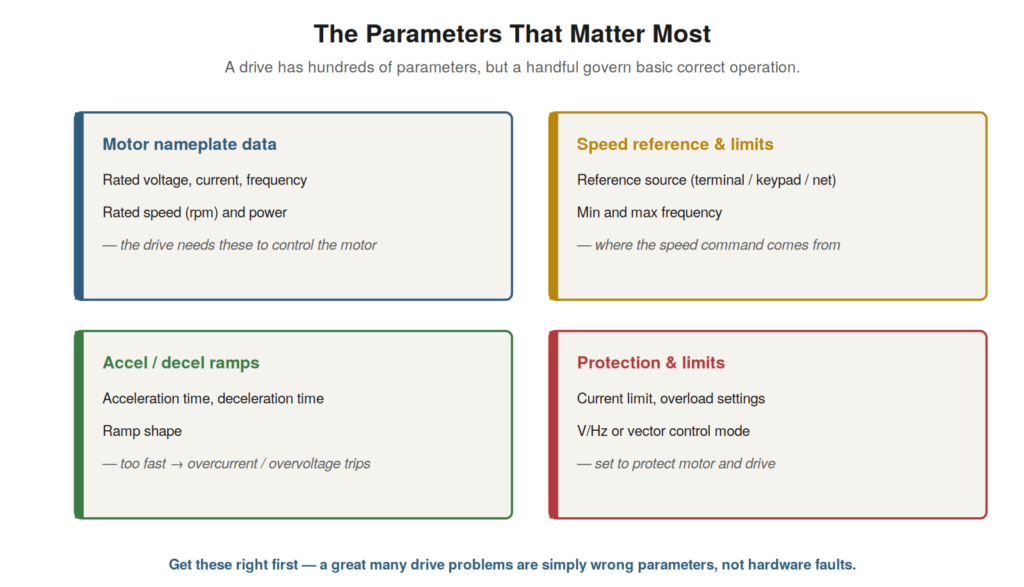
A drive has a daunting number of parameters, but only a handful
govern basic correct operation, and understanding these is essential to
setting up a drive and to troubleshooting the many problems that are
parameter-related. Rather than being overwhelmed by the full parameter
set, the technician who understands the key parameters — what they do
and how they interact — can commission a drive correctly and diagnose
the configuration errors that cause so many faults. This chapter focuses
on the parameters that matter most.
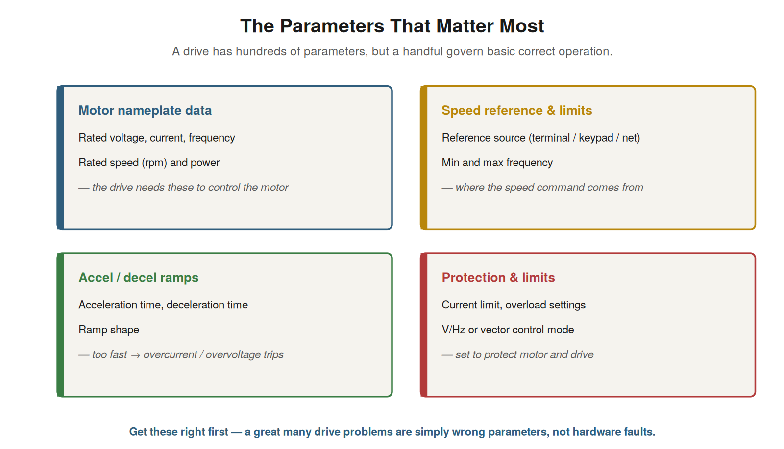
data, speed reference and limits, acceleration/deceleration ramps, and
protection and control mode. Get these right first — many drive problems
are wrong parameters, not hardware faults.
Motor data
The most fundamental parameters are the motor data — the motor’s
nameplate values entered into the drive so it knows the motor it is
controlling. The drive needs the motor’s rated voltage, current,
frequency, speed, and power to control it correctly: these tell the
drive how to apply the volts-per-hertz relationship, what current is
normal, and how the motor should behave. Entering the motor data
correctly, from the motor’s nameplate, is the foundation of correct
drive operation, because the drive’s control of the motor depends on
knowing the motor’s characteristics. Wrong motor data — a mistyped
value, or data from a different motor — causes the drive to control the
motor incorrectly, producing torque problems, current problems, and
faults. Understanding that the motor data parameters are fundamental —
the drive needs accurate motor nameplate values to control the motor
correctly — is essential to setup and troubleshooting. It reinforces
entering the motor data carefully and correctly from the nameplate, and
checking it when diagnosing problems, because incorrect motor data is a
common cause of drive-motor problems, causing the drive to mis-control a
motor whose true characteristics differ from the entered data. The motor
data is the drive’s knowledge of its motor, and getting it right is the
basis for correct control, making it a first thing to set correctly and
to verify in troubleshooting.
Speed reference, limits, and ramps
Several parameters govern how the drive is commanded and how it
responds: the speed reference source and limits, and the acceleration
and deceleration ramps. The reference source parameter tells the drive
where to get its speed command — from a control terminal signal, the
keypad, or a communication network — and getting this wrong means the
drive looks for its command in the wrong place, so it does not respond
as expected. The minimum and maximum frequency limits set the speed
range. The acceleration and deceleration ramp parameters set how quickly
the drive changes speed — and these are a common source of faults: too
fast an acceleration causes overcurrent (the drive forcing the motor to
accelerate quickly draws high current), and too fast a deceleration
causes overvoltage (the motor regenerating energy into the DC bus faster
than it can be absorbed). Understanding these parameters — reference
source, frequency limits, and ramp times — is important because they
govern the drive’s response to commands and because the ramps in
particular cause common faults. It reinforces setting these correctly
(the right reference source, sensible limits, ramps matched to the load)
and checking them in troubleshooting, especially the ramps when
diagnosing overcurrent (accel) or overvoltage (decel) faults, since
these very common faults are often simply ramps set too fast for the
load, a parameter issue resolved by adjusting the ramp times rather than
any hardware repair.
Control mode and protection
Two further groups of parameters shape the drive’s operation: the
control mode and the protection settings. The control mode parameter
sets how the drive controls the motor — simple volts-per-hertz control,
or more sophisticated vector control that regulates torque and speed
more precisely — and it must suit the application and be configured
correctly (vector control, for instance, needs accurate motor data and
sometimes an auto-tune procedure). The protection parameters set the
drive’s protective limits: the current limit, the motor overload
protection, and others, which must be set to protect the motor and drive
appropriately — too low causes nuisance trips, too high fails to
protect. Understanding these — the control mode determining how the
drive regulates the motor, and the protection parameters setting the
protective limits — completes the picture of the key parameters. It
reinforces configuring the control mode correctly for the application
(with the motor data and tuning it requires) and setting the protection
sensibly (to protect without nuisance-tripping). In troubleshooting, the
control mode matters (a mismatched or mis-tuned mode causes control
problems) and the protection settings matter (mis-set protection causes
nuisance trips or inadequate protection), so understanding these
parameters — alongside the motor data, reference, limits, and ramps —
covers the key configuration that governs correct drive operation and
that, when wrong, causes the many parameter-related faults that are so
common in drive troubleshooting.
Commissioning: getting it right first
Setting the key parameters correctly is the heart of commissioning a
drive — bringing it into service properly — and a systematic
commissioning prevents many faults that would otherwise appear later.
Commissioning proceeds in a sensible order: check the installation
(wiring, grounding, shielding, correct voltage rating), enter the motor
nameplate data, set the basics (reference source, frequency limits,
ramps), set the control mode (running an auto-tune if the drive offers
one), set the protection, then test — first at low speed or uncoupled to
check rotation and smooth running, then under load to verify the current
is within limits and the speed control works without trips. Finally, the
full parameter set is recorded and backed up.
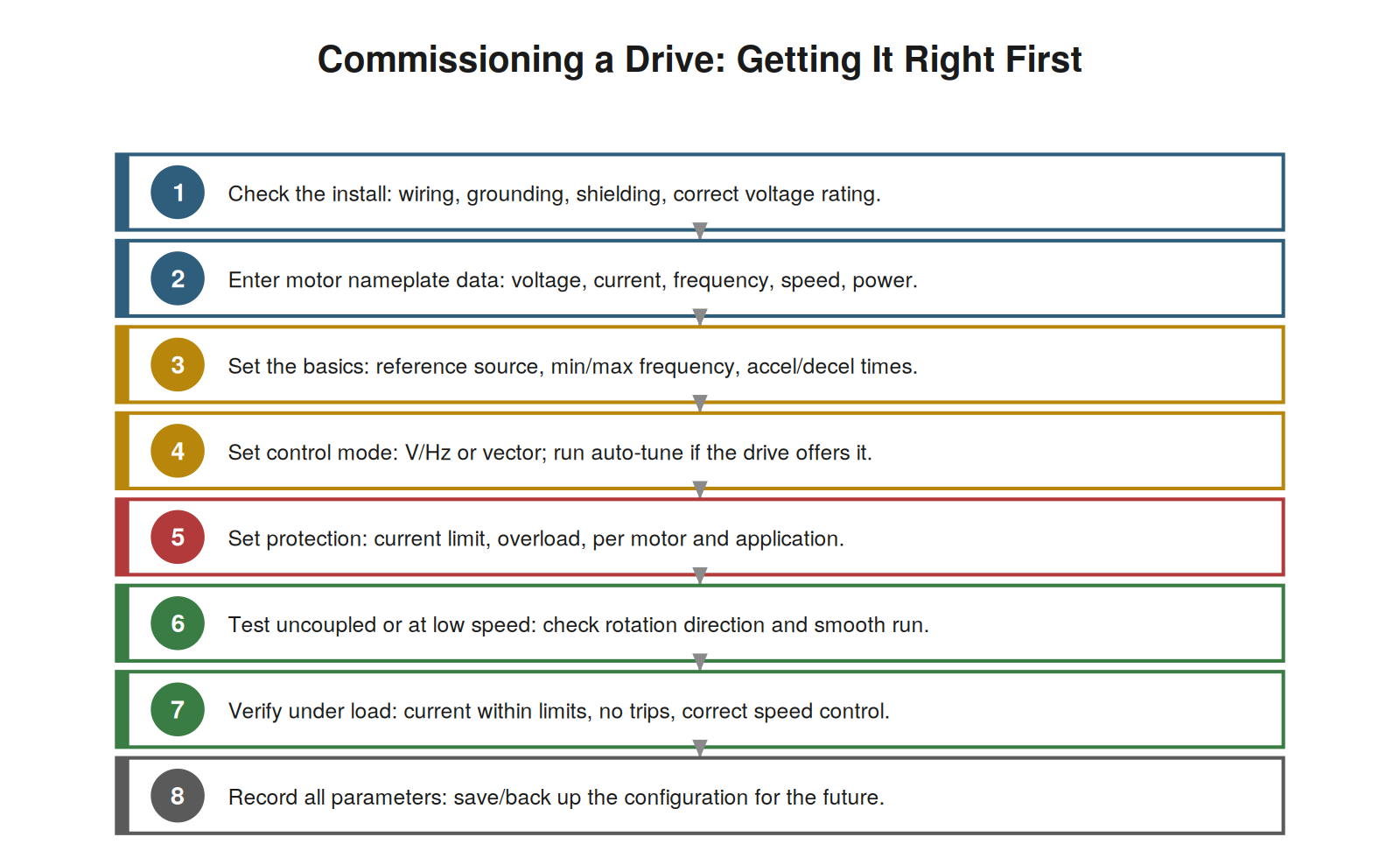
motor data, set the basics and control mode, set protection, test
uncoupled and then under load, and record the parameters. A drive
commissioned carefully rarely faults from setup errors later.
Commissioning carefully at the start is worth the effort, because a
drive brought into service properly — correctly installed, with accurate
motor data, sensible settings, and verified operation — rarely suffers
the setup-related faults that plague a hastily-commissioned drive. Many
of the parameter-related faults discussed throughout this book originate
in commissioning shortcuts: wrong motor data, unsuitable ramps, wrong
reference source, mis-set protection. A systematic commissioning that
gets these right, and verifies the drive’s operation before leaving it
in service, prevents these faults from arising. Understanding
commissioning as the systematic setting and verifying of the drive’s
configuration — install, motor data, basics, mode, protection, test,
record — reinforces doing it carefully. It reinforces that the effort of
a proper commissioning pays off in reliable operation free of
setup-related faults, because the drive is correctly configured and
verified from the start, and that the recorded parameter backup, made at
commissioning, protects the configuration and aids any future
troubleshooting, making a careful commissioning the foundation of a
reliably-operating drive.
Default parameters and where they fall short
Drives come with default parameter values, and understanding the role
and limits of these defaults helps in setup and troubleshooting. The
defaults are the manufacturer’s initial settings, chosen to be
reasonable for a generic application, and they let a drive run in a
basic way without every parameter being set. But defaults are generic,
not tailored to the specific motor and application, so they often need
adjustment: the motor data must be set to the actual motor (defaults
cannot know it), the ramps and limits may need tuning to the load, the
reference source must match the installation. Relying on defaults where
they do not fit causes problems — wrong motor data, unsuitable ramps,
wrong reference source. So the defaults are a starting point, not a
complete configuration, and proper setup adjusts them to the specific
application. Understanding the role of defaults — a generic starting
point needing adjustment to the specific motor and application —
clarifies their use and limits. It reinforces that commissioning a drive
means setting the parameters to the actual application, not just
accepting defaults, because the defaults, while a reasonable starting
point, do not fit the specific motor and load, and relying on them where
they fall short causes problems. Understanding that defaults are generic
and need tailoring reinforces proper commissioning — adjusting the key
parameters to the actual application — rather than leaving inappropriate
defaults that cause the parameter-related problems the defaults’
genericness invites.
Scenario: the accel ramp that tripped the drive
A scenario shows a ramp parameter causing a fault. A drive tripped on
overcurrent every time it started a high-inertia load, and the motor,
cable, and drive all tested fine — no hardware fault. Checking the
parameters revealed the acceleration ramp was set very fast, commanding
the drive to accelerate the heavy, high-inertia load quickly. To do so,
the drive had to force a large current into the motor, which exceeded
the overcurrent limit and tripped the drive. The cause was the too-fast
acceleration ramp for the high-inertia load — a parameter issue, not a
hardware fault. Extending the acceleration ramp, so the drive
accelerated the load more gradually with less current, stopped the
overcurrent trips, and the load started smoothly. This scenario shows a
ramp parameter — too-fast acceleration — causing overcurrent trips with
no hardware fault. Understanding that the acceleration ramp affects the
starting current (faster ramp, more current) explains this: the fast
ramp forced excessive current, tripping the overcurrent, and the fix was
to slow the ramp. It reinforces checking the ramp parameters when
diagnosing overcurrent on acceleration (or overvoltage on deceleration),
because these very common faults are often simply ramps set too fast for
the load — a parameter issue resolved by adjusting the ramp times. The
scenario reinforces that the ramp parameters are a frequent cause of
overcurrent (accel) and overvoltage (decel) faults, and that adjusting
them — here extending the acceleration ramp — resolves these common
parameter-related faults without any hardware repair.
Resetting to defaults as a diagnostic
A useful technique when parameter problems are suspected but hard to
pin down is resetting to defaults, and understanding when and how to use
it aids parameter troubleshooting. If a drive misbehaves and the
configuration is suspected but the specific wrong parameter cannot be
found (perhaps through parameter interactions or an unknown history of
changes), resetting the parameters to the manufacturer’s defaults and
then re-entering the known-correct configuration (motor data, key
settings) can clear an obscure parameter problem. This gives a known
starting point — the defaults — from which the correct configuration is
rebuilt, eliminating any hidden wrong or interacting parameters. It must
be done carefully: the correct configuration must be known and
re-entered (defaults alone will not fit the application), and the reset
should be recorded. Understanding this technique — resetting to defaults
and rebuilding the configuration to clear obscure parameter problems —
provides a tool for difficult parameter issues. It reinforces that when
a parameter problem is suspected but elusive, resetting to defaults and
re-entering the known-correct settings can clear it by starting from a
clean, known state, provided the correct configuration is known and
re-applied. Understanding resetting to defaults as a diagnostic
technique — clearing hidden parameter problems by starting fresh and
rebuilding — adds a tool for difficult configuration issues, useful when
a parameter problem defies specific identification, though it requires
knowing and re-entering the correct configuration, making the parameter
backup and documentation (which provide the correct configuration to
restore) valuable in support of this technique.
Get the basics right first
A consolidating principle for the key parameters is to get the basics
right first, and recognizing this guides both commissioning and
troubleshooting. The handful of key parameters — motor data, reference
and limits, ramps, control mode, and protection — govern basic correct
operation, so getting these right first establishes a working foundation
before any fine-tuning. In commissioning, this means setting the basics
correctly at the start; in troubleshooting, it means checking these
basics first when a problem might be parameter-related, since they are
the most likely and most consequential to be wrong. Getting the basics
right first — the motor data accurate, the reference and limits
sensible, the ramps matched to the load, the mode and protection correct
— resolves or prevents most parameter problems, which involve these key
settings. Recognizing the principle of getting the basics right first
guides efficient commissioning and troubleshooting: focus on the key
parameters that govern basic operation. It reinforces that among the
many parameters, the key basics matter most and should be set and
checked first, because they govern correct operation and are the most
likely parameter causes of problems. Understanding to get the basics
right first — the key parameters that govern basic operation —
consolidates the approach to parameters: rather than being overwhelmed
by the full set, focus on the handful of key parameters, getting them
right in commissioning and checking them first in troubleshooting, which
addresses the most likely and consequential parameter issues efficiently
and establishes the working foundation that correct basic operation
requires.