Two subtle but important measurement concepts — voltage drop and the reference point — deserve their own chapter, because understanding them catches a class of faults that simpler measurements miss and prevents a common source of confusion. Voltage drop reveals high-resistance connections that a continuity test would pass, and understanding the reference point clarifies what a voltage reading actually means. This chapter covers these concepts, which deepen your measurement skill considerably.
Voltage drop: the silent fault
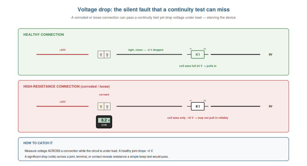
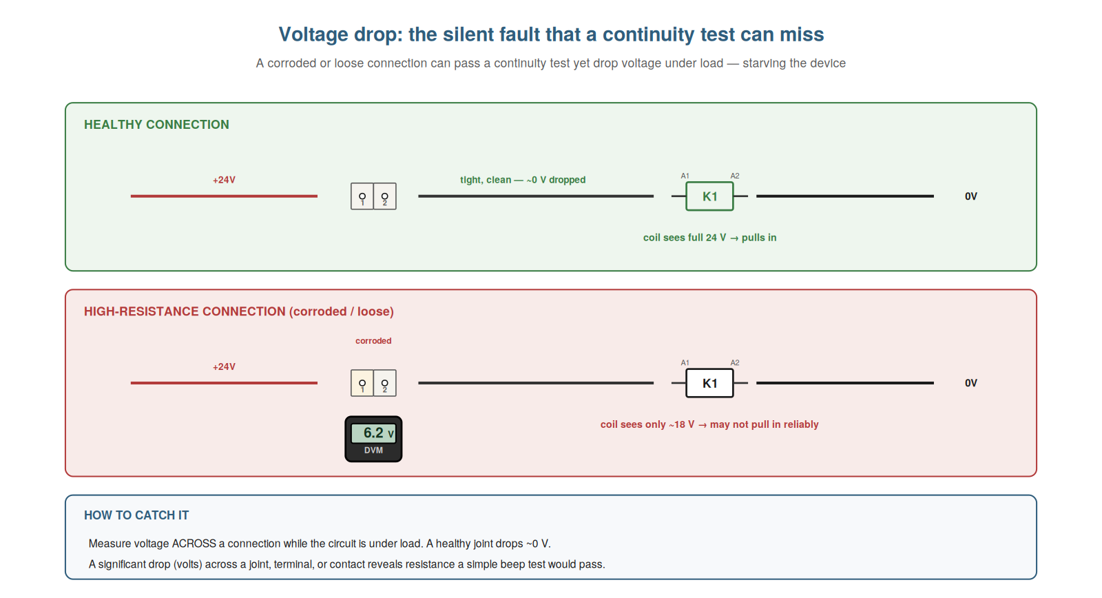
Voltage drop is a silent fault that simpler tests miss, and understanding it lets you catch high-resistance connections that would otherwise puzzle you. A connection that is not fully broken but has become high-resistance — a corroded terminal, a loose screw, a partly-broken wire — can still pass a continuity test (there is a path, so it beeps) yet cause trouble under load: when current flows through the high resistance, a voltage is dropped across it, so the device beyond it receives less than the full 24 volts, and may work weakly, unreliably, or not at all. This is silent because continuity says the path is fine, yet the device misbehaves. The way to catch it is to measure voltage across the connection while the circuit is under load: a healthy connection drops almost no voltage (near 0 volts across it), while a high-resistance one drops a significant voltage (volts across it), revealing the resistance. So voltage drop under load reveals the high-resistance fault that continuity misses. Understanding voltage drop — the silent high-resistance fault caught by measuring across a connection under load — lets you catch faults that puzzle those relying on continuity alone. Understanding voltage drop as the silent fault — the high-resistance connection that passes a continuity test yet drops voltage under load, starving the device — lets you catch a class of faults that simpler measurements miss, so that when a device works weakly or unreliably despite the path appearing intact, you measure the voltage across suspect connections under load and find the culprit: a healthy joint drops almost nothing, while a corroded or loose one drops significant voltage, revealing the resistance that a continuity test passed and explaining the puzzling weak or unreliable operation.
Understanding the reference point
A concept that prevents much confusion is understanding the reference point of a voltage measurement, because a voltage reading only means something with respect to a reference. Voltage is always measured between two points — it is a difference — so a reading depends on where both leads are. In control-circuit work, you usually measure with respect to a 0V reference (the black lead on 0V), so that a reading tells you the voltage at the red probe’s point relative to 0V. Understanding this prevents confusion: a reading of 24 volts means the probed point is 24 volts above the 0V reference; a reading of 0 volts means it is at the same potential as 0V (either it is the 0V, or the +24V has not reached it). If you unknowingly reference a different point, the readings mean something different and can confuse. So understanding the reference point — that a voltage reading is relative to where the black lead is — clarifies what every reading means and prevents the confusion of misinterpreting a measurement whose reference you have not tracked. Understanding the reference point — that a voltage reading is always relative to where the reference (black) lead is — clarifies what a measurement means and prevents confusion. Understanding the reference point — that voltage is a difference between two points, so a reading only means something with respect to where the black lead sits, usually a 0V reference — clarifies what every voltage measurement actually tells you and prevents a common source of confusion, so that you always know a 24-volt reading means the probed point is 24 volts above your reference and a 0-volt reading means it is at the reference potential, and you track where your reference lead is, which keeps your measurements meaningful and avoids the misinterpretation that comes from not knowing what a reading is referenced to.
Putting drop and reference together
Bringing these concepts together, understanding how voltage drop and the reference point combine sharpens your voltage measurement into a precise diagnostic. The reference point concept tells you that where you put the black lead determines what a reading means; the voltage-drop concept tells you that measuring across a connection (both leads on either side of it) reveals resistance. Combining them: to measure voltage drop across a connection, you place the leads on either side of that connection (not referenced to 0V, but across the connection itself), reading the difference — the drop — across it. This is a different, deliberate use of the reference: the reference is now one side of the connection, and you read the drop to the other side. Understanding both concepts lets you choose your reference deliberately for what you want to measure: 0V reference for tracing where voltage disappears (finding opens), or across-a-connection for measuring drop (finding high resistance). So putting drop and reference together lets you use voltage measurement precisely for different diagnostic purposes. Understanding how voltage drop and the reference point combine — choosing your reference deliberately to trace voltage or measure drop — sharpens your voltage measurement into a precise diagnostic. Understanding how to put voltage drop and the reference point together — choosing where to place your reference lead deliberately, whether on 0V to trace where voltage disappears along a path or across a connection to measure the drop over it — sharpens your voltage measurement into a precise diagnostic, so that you use the reference point concept consciously to serve your purpose: referencing 0V to find opens by where the voltage vanishes, or referencing across a connection to find high resistance by the drop it causes, which turns voltage measurement from a single technique into a precise, purpose-chosen diagnostic that finds both opens and the silent high-resistance faults that voltage drop reveals.
Why voltage drop only shows under load
An important subtlety is why voltage drop only appears under load, because understanding it explains why you must measure with the circuit working and why a no-load test can miss the fault. Voltage drop across a resistance depends on current flowing through it: with no current, there is no drop, regardless of the resistance (a high-resistance connection with no current flowing shows no voltage across it). Only when load current flows does the resistance produce a voltage drop. So a high-resistance connection is invisible at no load — it drops nothing, and even a voltage reading past it looks fine — but under load it drops significant voltage, starving the device. This is why you must measure voltage drop with the circuit under load (the device operating, current flowing): only then does the drop appear. A test with no current flowing (or a continuity test, which uses only a tiny current) will not reveal it. So understanding why drop only shows under load explains the need to measure under working conditions. Understanding why voltage drop only shows under load — that a drop needs current flowing through the resistance — explains why you measure under working conditions and why no-load tests miss it. Understanding why voltage drop only shows under load — that the drop across a resistance requires current flowing through it, so a high-resistance connection is invisible at no load and only drops significant voltage when load current flows — explains why you must measure voltage drop with the circuit under load and why a no-load or continuity test misses the fault, so that you know to test with the device operating and current flowing, which is the only condition under which the drop appears, and you understand why the fault can hide from tests that do not draw the working current, making load conditions essential to catching voltage-drop faults.
Scenario: the connection that passed continuity but failed under load
A scenario shows voltage drop catching a fault that continuity missed. A device worked weakly and unreliably, yet every wire and connection passed a continuity test — they all beeped, so the path seemed fine, baffling the technician. Understanding voltage drop, he realized continuity (a tiny test current) would not reveal a high-resistance connection that only drops voltage under load. So he measured voltage drop under load: with the device operating, he probed across each connection in turn, and found one terminal dropping several volts across it while the others dropped nearly none. That corroded terminal was the culprit — it passed continuity (a path existed) but dropped voltage under load (high resistance), starving the device. Cleaning and remaking the connection restored full voltage and reliable operation. Voltage-drop measurement under load had caught what continuity missed. This scenario shows voltage drop catching a high-resistance fault that continuity passed. Understanding voltage drop under load let the technician find the corroded connection that continuity missed. It reinforces that voltage drop under load reveals high-resistance connections that pass a continuity test. The scenario reinforces voltage drop: the technician caught a corroded connection that passed continuity but failed under load by measuring the voltage drop across connections while the device operated, finding the one dropping several volts, illustrating how voltage-drop measurement under load reveals the high-resistance faults that a continuity test — with its tiny current — cannot detect, catching the silent fault behind a weak, unreliable device.
Comparing the two rails’ references
A nuance that sharpens reference-point understanding is that you can reference either rail, and understanding when to use each clarifies what different measurements tell you. Usually you reference 0V (black lead on 0V) and measure how far up toward 24 volts a point is — good for tracing the +24V side, where a point reading 24 means the positive path is good to there. But you can also reference +24V (black lead on +24V) and measure how far down toward 0V a point is — useful for tracing the 0V (return) side of the circuit, where a fault in the return path is what you seek. A break in the return path (between the load and 0V) is found by referencing +24V and probing the return: where the reading changes reveals the break in the return. So understanding that you can reference either rail lets you trace either side of the circuit: 0V reference for the positive feed, +24V reference for the return. This is useful because a fault can be in the return path as well as the feed, and choosing the right reference targets the side you are investigating. Understanding how to compare the two rails’ references — referencing 0V to trace the feed, +24V to trace the return — lets you investigate either side of the circuit. Understanding how to compare the two rails’ references — referencing 0V to trace the positive feed and +24V to trace the 0V return path — lets you investigate either side of the circuit, so that you can find a break in the feed by referencing 0V and walking the positive path, or a break in the return by referencing +24V and walking the return path, choosing your reference to target the side you suspect, which sharpens your reference-point understanding into the practical ability to trace faults on either the feed or the return, wherever the open lies in the complete path.
Deliberate measurement as the goal
To close, it helps to see deliberate measurement — knowing exactly what you are measuring and why — as the goal these concepts serve, because it is what raises measuring from mechanical to skilled. The reference-point and voltage-drop concepts both come down to deliberateness: knowing where your reference is and what a reading means, and choosing to measure across a connection under load to reveal resistance. A skilled technician measures deliberately — each measurement chosen for a reason, each reading interpreted knowingly — rather than probing points and hoping. So deliberate measurement is the goal, and the reference-point and voltage-drop understanding are what make it possible. Understanding deliberate measurement as the goal — knowing what you measure and why — raises measuring from mechanical to skilled. Understanding deliberate measurement as the goal — knowing exactly where your reference is, what each reading means, and why you are taking it, and choosing measurements like voltage-drop-under-load for a reason — raises your measuring from mechanical probing to skilled diagnosis, so that the reference-point and voltage-drop concepts serve the larger aim of measuring deliberately, each reading chosen and interpreted knowingly, which is what distinguishes the skilled troubleshooter’s purposeful measurement from aimless probing and the deeper value of understanding the reference point and voltage drop.