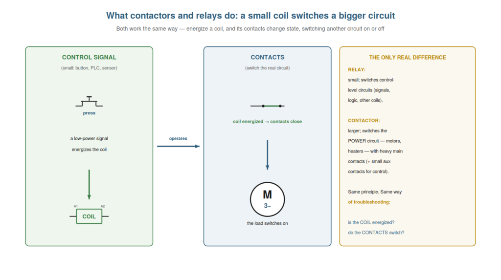
Before troubleshooting contactors and relays, you need a clear picture of what they do and why they exist. At their simplest, both are switches operated by an electromagnet: a small current through a coil pulls a set of contacts closed, switching another circuit. This lets a small, safe control signal — from a button, a sensor, or a PLC — switch a much larger or separate circuit, such as a motor’s power supply. Understanding this basic role — a coil-operated switch that lets a small signal control a bigger circuit — is the foundation for everything that follows, because every fault is ultimately about the coil not operating or the contacts not switching.
The coil-and-contacts principle
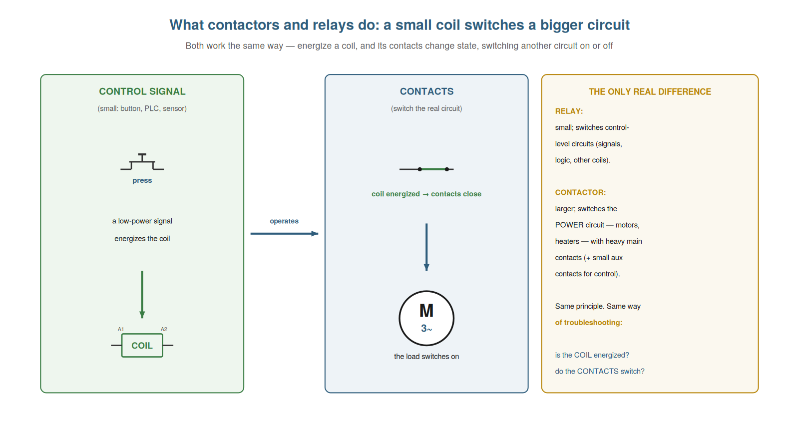
The single principle underlying both contactors and relays is the coil-and-contacts mechanism, and understanding it is the key to troubleshooting either. The device has two functional parts: a coil (the input) and a set of contacts (the output). When current flows through the coil, it becomes an electromagnet and mechanically pulls the contacts to change state — normally-open contacts close, normally-closed contacts open. When the coil current stops, a spring returns the contacts to their resting state. So a small current through the coil switches the contacts, which can carry a separate, larger circuit. This coil-and-contacts operation is the whole essence: the coil is what you energize to operate the device, and the contacts are what do the switching. Understanding this two-part structure is the foundation of troubleshooting, because every fault is either the coil failing to operate (an input problem) or the contacts failing to switch properly (an output problem). So the coil-and-contacts principle frames every contactor and relay fault as a question of which part has failed. Understanding the coil-and-contacts principle — the coil that energizes to move the contacts, and the contacts that switch another circuit — is the key to troubleshooting either device, because it divides every possible fault into two clear categories: the coil not operating (not energized, or a failed coil) or the contacts not switching (not making, worn, or welded), which turns the diagnosis of any contactor or relay into the simple, powerful question of whether the fault is on the coil side or the contact side, the foundation of the whole book.
Relay versus contactor
Though they work identically, it helps to understand the difference between a relay and a contactor, because it tells you what each is for and what its faults tend to involve. A relay is small: it switches control-level circuits — signals, logic, small loads, other coils — and is often a plug-in device with a status LED. A contactor is larger: it switches the power circuit — motors, heaters, high current — with heavy main contacts built to make and break large currents, plus smaller auxiliary contacts used for control and feedback. The coil principle is the same in both, but the scale differs: a relay’s contacts handle small currents, a contactor’s main contacts handle the power. This difference shapes their faults: a contactor’s main contacts take the punishment of switching heavy loads (wear, welding, burning), while a relay’s faults more often involve its small contacts, its socket, or its coil. Understanding the distinction tells you what you are dealing with and where its faults tend to lie. So understanding relay versus contactor — small control switch versus large power switch, same principle — clarifies what each does and what its faults involve. Understanding the difference between a relay and a contactor — the relay as a small switch for control-level circuits, often plug-in with an LED, and the contactor as a larger switch for the power circuit with heavy main contacts and auxiliary contacts, both working by the same coil principle — clarifies what each is for and what its faults tend to involve, so that you recognize a contactor’s main contacts take the punishment of switching heavy loads (leading to wear, welding, and burning) while a relay’s faults more often involve its small contacts, its socket and pins, or its coil, which orients your troubleshooting to the likely faults of the specific device in front of you.
Why we use them
Understanding why contactors and relays are used — the reasons a coil-operated switch is so valuable — helps you appreciate their role and reason about faults in context. They exist because they let a small signal control a big or separate circuit safely and remotely: a low-voltage button or a PLC output (which cannot itself switch a motor’s power) energizes a coil, and the coil’s contacts switch the motor — so the control side stays small and safe while the device does the heavy switching. They provide isolation between the control circuit and the switched circuit (the coil and contacts are electrically separate), allow one signal to switch several circuits (multiple contacts on one device), and enable control logic (contacts feeding back into other coil circuits for seal-in, interlocking, and sequencing). So they are used to control power with a signal, to isolate, to multiply, and to build logic. Understanding these purposes helps you see a device in its context: when it fails, you understand what function is lost and why the circuit is built as it is. So understanding why we use contactors and relays — to control big circuits with small signals, safely and logically — puts each device’s role in context for troubleshooting. Understanding why we use contactors and relays — to let a small, safe control signal switch a large or separate power circuit, providing isolation between control and power, allowing one signal to switch several circuits, and enabling the seal-in, interlock, and sequencing logic built from their contacts — helps you appreciate each device’s role and reason about its faults in context, so that when one fails you understand what function is lost and why the circuit around it is built as it is, which turns troubleshooting from swapping an isolated part into understanding a device within the control scheme it serves.
Poles, ways, and how contacts are counted
A practical detail worth understanding is how contacts are counted and described — poles and ways — because it helps you read a device’s specification and order the right one. A ‘pole’ is a switched circuit (a set of contacts switching one line); a contactor for a three-phase motor is three-pole (switching all three phases). A ‘way’ or ‘throw’ describes what each pole connects to: a single-throw contact simply makes or breaks (NO or NC), while a double-throw (changeover) contact switches a common between two positions. So a device is described by how many poles it has and whether they are NO, NC, or changeover, plus how many auxiliary contacts of each type. Understanding this lets you read a specification (a three-pole contactor with one NO and one NC aux, say) and match a replacement to it. It also tells you the device’s switching capability: how many separate circuits it switches, and in what way. So understanding poles, ways, and contact counting helps you read specifications and select correctly. Understanding poles, ways, and how contacts are counted — a pole being one switched circuit (a three-phase contactor being three-pole), and the way describing whether a contact makes/breaks or changes over, plus the count of auxiliary contacts — helps you read a device’s specification and select the right one, so that you can interpret a description like a three-pole contactor with one NO and one NC auxiliary, match a replacement to it, and understand how many circuits the device switches and in what way, which is a practical part of reading and ordering the contactors and relays you work with.
Scenario: the technician who swapped the wrong thing
A scenario shows the value of understanding what these devices do. A machine would not start, and a technician, seeing the motor dead, immediately replaced the contactor — which did not fix it. Understanding the coil-and-contacts principle would have saved the effort: the contactor is a coil that switches contacts, so the question is whether the coil was energized (a control-circuit issue) or the contacts were failing (a device issue). Had he measured the coil first, he would have found it was not energized — the fault was in the control circuit feeding the coil (a tripped overload, as it turned out), not the contactor at all. Replacing the contactor was swapping the wrong thing, because the device was fine; its coil simply was not being fed. Understanding what the contactor does — and that a dead motor could be the coil not fed or the contacts not switching — would have directed him to measure the coil before replacing anything. This scenario shows how understanding the coil-and-contacts principle prevents swapping the wrong part. Understanding that a contactor is a coil switching contacts, so a dead load could be an unfed coil or failing contacts, would have led the technician to measure the coil before replacing the device. It reinforces that the coil-and-contacts split directs you to check the coil before assuming the device is faulty. The scenario reinforces the chapter’s principle: understanding what contactors and relays do — a coil switching contacts, so a fault is the coil not operating or the contacts not switching — directs you to measure the coil before swapping the device, which the technician learned when replacing a fine contactor failed to fix a fault that was really a tripped overload not feeding its coil.
Where these devices sit between PLC and motor
A point worth understanding is where contactors and relays sit in the chain from a PLC to a motor, because it clarifies their role in modern control and where to look when that chain fails. A typical modern chain runs: a PLC output (low-power, cannot switch a motor) drives a small interface relay’s coil; the relay’s contact switches the contactor’s coil (or the PLC output drives the contactor coil directly if rated); the contactor’s main contacts switch the motor’s power. So these devices form the bridge from the low-power control logic (the PLC) to the high-power load (the motor), stepping up from a signal to switched power in stages. Understanding this chain clarifies where each device sits and where to look when the motor does not respond to a PLC command: is the PLC output on? does the interface relay switch? is the contactor coil energized? do the main contacts close? Each stage is a place to check. So understanding where these devices sit between PLC and motor clarifies the control chain and where to look. Understanding where contactors and relays sit between a PLC and a motor — the PLC output driving an interface relay, the relay switching the contactor coil, and the contactor’s main contacts switching the motor, stepping from a low-power signal to switched power — clarifies their role in modern control and where to look when the chain fails, so that when a motor does not respond to a PLC command you check each stage in turn (PLC output on? relay switching? contactor coil energized? main contacts closed?), which locates the fault within the chain from control logic to load that these devices bridge.
Why the coil-and-contacts split pays off
It is worth closing this chapter by appreciating why the coil-and-contacts split pays off, because it justifies learning the principle before diving into faults. A technician who understands every contactor and relay as a coil that moves contacts approaches every fault with a ready framework: is the coil operating, or are the contacts switching? This one split localizes most faults immediately — to the input side (coil and its feed) or the output side (contacts and their switching) — before any detailed work. Without it, troubleshooting is blind device-swapping; with it, every fault starts with a clear, halving question. So the coil-and-contacts split pays off by turning every fault into a reasoned two-way diagnosis, which is why understanding it first is worth the effort. Understanding why the coil-and-contacts split pays off — that seeing every device as a coil moving contacts turns every fault into a localizing question rather than blind swapping — justifies learning the principle first, so that you appreciate the split not as abstract theory but as the framework that makes every diagnosis start with a clear question and localize the fault to the coil side or the contact side, which is why this book builds on the coil-and-contacts principle and why understanding what contactors and relays do repays itself in every fault you later resolve with the split it provides.