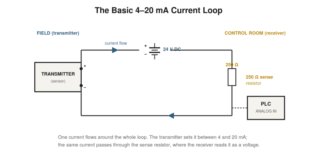
At its heart, a 4–20 mA current loop is one of the simplest ideas in instrumentation: a single electrical current, flowing around a closed loop of wire, whose magnitude represents a measurement. A transmitter out in the plant measures something — a pressure, a temperature, a level — and adjusts the current it allows to flow so that the current is proportional to the measured value. A receiver, often a control system input, senses that same current and converts it back into a reading. The current is the message, and it travels the loop from transmitter to receiver as a faithful analog of the measured quantity.
One current, one loop
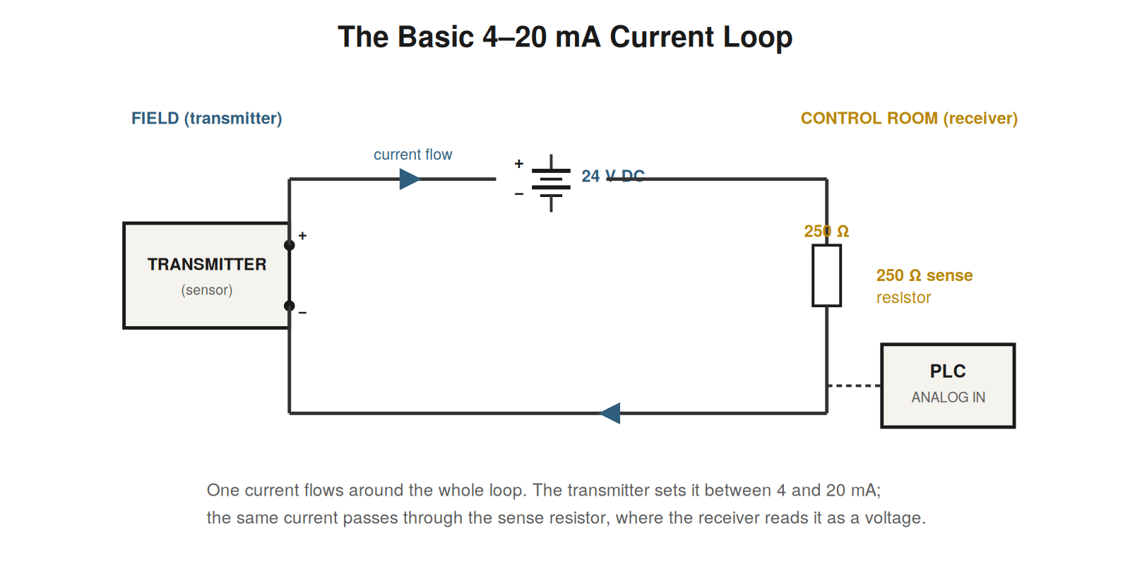
The defining feature of the loop is that it is a series circuit: the current is the same at every point around it. Whatever the transmitter sets the current to, that identical current flows through the wiring, through any devices in the loop, and through the receiver, before returning to complete the circuit. This is the essential picture to hold in mind — not several signals but one current, shared by everything in the loop. Because it is a series circuit, the current is determined by the transmitter (which acts to regulate it) and is unaffected by where you measure it, since it is the same everywhere. Understanding the loop as a single series current is the foundation for everything that follows, from wiring to scaling to troubleshooting.
The parts of a loop
A basic loop has a few essential parts. First, a power source — typically a 24-volt DC supply — that provides the energy for the current to flow, since the loop is a powered circuit, not a self-generating one. Second, a transmitter, the field device that measures the process variable and regulates the loop current between 4 and 20 mA in proportion to it. Third, the wiring that carries the current out to the field and back. And fourth, a receiver — the device that senses the current and interprets it, most often by passing the current through a precise sense resistor and reading the resulting voltage, which a control system’s analog input can measure. These four elements — supply, transmitter, wiring, and receiver — make up the loop, and every loop is a variation on this arrangement.
The transmitter as a current regulator
The most important thing to understand about the transmitter is that it does not simply produce a voltage; it regulates the current in the loop. Whatever the loop’s supply voltage and whatever the resistance of the wiring and receiver (within limits), the transmitter adjusts itself to make the loop current equal to the value representing its measurement. If the measurement is at the bottom of its range, the transmitter allows 4 mA to flow; at the top, 20 mA; and proportionally in between. This active regulation of current — rather than the passive production of a voltage — is what gives the current loop its remarkable robustness, as the next chapters explain, because a regulated current behaves very differently from a voltage when it meets the imperfections of real wiring.
A tale of two signals
Imagine two ways to send a pressure reading from a tank in the yard to a control room a hundred meters away. The first sends a voltage proportional to pressure down a pair of wires; the second sends a current. On paper both seem fine, but in the real plant they behave very differently. The voltage arrives at the control room slightly wrong, because the long wires dropped a little of it along the way, and the error grows with distance and changes as the wires warm and cool. The current arrives exactly as it left, because in a series loop the current is the same everywhere no matter what the wires do. The 4–20 mA loop is the second approach made standard, and this single property — that the current is preserved end to end — is the root of its long dominance in industrial measurement. Everything else about the loop builds on this foundation of a current that travels undistorted from field to control room.
Why the loop endures
The 4–20 mA loop has survived decades of technological change — through the rise of digital fieldbuses, industrial Ethernet, and wireless — and remains ubiquitous, which tells you something about its qualities. It endures because it is simple, robust, and good enough for a huge range of measurements. A single pair of wires carries a self-powering, noise-resistant, distance-tolerant signal with built-in fault detection, and it interoperates across manufacturers and generations of equipment. Newer digital systems offer more data and features, but they add complexity, and for the simple job of carrying one analog measurement reliably, the current loop is hard to beat. Its endurance means the skill of understanding and troubleshooting it will remain valuable for a very long time, because the enormous installed base of loops will not disappear, and new loops continue to be installed where their simplicity and robustness suit the task. Learning the loop well is therefore an investment in a durable, not a fading, skill.
The loop from the transmitter’s point of view
It clarifies the loop to see it from the transmitter’s point of view. The transmitter’s job is to hold the loop current at a value representing its measurement, and to do this it behaves like an adjustable regulator: it senses how much current is flowing and adjusts itself to make that current equal to the target. If the target is 12 mA and less is flowing, it opens up to let more through; if more is flowing, it restricts. It does this continuously, so that whatever the loop’s supply voltage and resistance (within its capability), the current settles at the value the transmitter wants. This active regulation is why the current is immune to wire resistance: the transmitter simply adjusts to whatever the loop conditions are to achieve its target current. Seeing the loop from the transmitter’s side — as a device actively holding the current at its target regardless of loop conditions — explains the loop’s robustness and demystifies how one current can be maintained accurately across varying wire runs and loads. The transmitter is the active element that makes the whole scheme work.
The four elements, and how faults map to them
Because a loop has just four essential elements — supply, transmitter, wiring, and receiver — loop faults ultimately live in one of these four places, which is a useful organizing thought for troubleshooting. A fault is in the supply (no or wrong power), the transmitter (failed, misconfigured, or wrong signal), the wiring (broken, high-resistance, or noisy), or the receiver (failed input, or wrong scaling). Every loop problem reduces to one of these, and the whole aim of troubleshooting is to determine which. This four-element structure underlies the systematic method: checking power addresses the supply; splitting the loop separates transmitter and wiring from receiver; isolating and injecting distinguish transmitter from wiring and test the receiver; and checking scaling addresses the receiver’s interpretation. Keeping the four elements in mind gives troubleshooting a clear target — identify which of the four holds the fault — and structures the diagnosis around narrowing the fault to one element and then to the specific problem within it. The simplicity of the loop, with only four places a fault can be, is part of what makes it tractable to troubleshoot systematically.
The loop as a teaching circuit
The current loop is an ideal circuit for learning practical electrical reasoning, because it is simple enough to understand completely yet rich enough to exhibit real behavior. It has just a few elements, one current, and a handful of relationships, so you can hold the whole thing in your head and reason about it fully — unlike a complex circuit where understanding is necessarily partial. Yet within this simplicity, the loop shows genuine electrical phenomena: series current, voltage drops, the voltage budget, the effect of resistance, noise and shielding. Learning the loop thoroughly therefore teaches transferable circuit reasoning: the habit of thinking about where the current flows, how the voltages distribute, what the resistances do, and how faults manifest. These habits, learned on the simple and comprehensible loop, apply to circuits generally. So mastering the current loop is not only a specific instrumentation skill but a training in practical circuit thinking, and the clarity that comes from fully understanding this small circuit builds the reasoning that serves you on larger ones. The loop rewards complete understanding precisely because it is small enough to understand completely, and that complete understanding is both directly useful and a foundation for broader electrical competence.
Where loops are found
It helps to picture where current loops actually live in a plant, because it shows the breadth of the skill. Loops carry the readings of pressure transmitters on vessels and pipes, temperature transmitters on processes and equipment, level transmitters on tanks, and flow transmitters in lines — the four measurements that dominate process instrumentation. They run from these field devices, often through hazardous areas and long cable runs, into marshalling panels and then to control-system inputs, where the readings drive displays, alarms, and control loops. A single plant may have hundreds or thousands of such loops, forming the sensory nervous system by which the control system perceives the process. Every one of these is a 4–20 mA loop of the kind this book covers, so the skill of understanding and troubleshooting loops applies across the entire instrumentation of a plant. Picturing this — loops everywhere, carrying every measurement, forming the plant’s sensory system — conveys why loop competence is so broadly useful: wherever a process variable is measured and sent to a control system, there is likely a current loop, and the ability to work with it applies to the whole vast population of measurements a plant depends on.
The loop as the sensory link
A helpful way to frame the current loop is as the sensory link between the process and the control system — the pathway by which the control system perceives what is happening in the plant. The process has physical conditions (pressures, temperatures, levels, flows); the control system needs to know them to display, alarm, and control; and the current loop is the link that carries this knowledge from the field sensor to the control system. Each loop is one sensory pathway, carrying one measurement, and together the plant’s loops form the complete sensory system by which the control system perceives the process. Seeing loops this way — as the sensory links — conveys their importance: they are how the control system knows anything about the process, so a faulty loop is a faulty sense, blinding the control system to one measurement. This framing also explains why loop reliability matters so much: the control system can only act on what it perceives through its loops, so a wrong or dead loop leads to wrong or absent perception and thus wrong or absent control. The current loop, as the sensory link, is fundamental to the whole control system’s function, which is why understanding and maintaining loops is so important — they are the plant’s senses, and the control depends entirely on their fidelity.