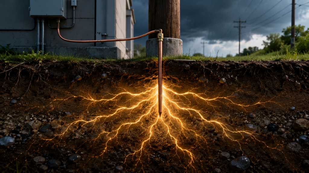
A live wire touches a metal enclosure. Current rushes into the grounding system. The circuit breaker trips.
Problem solved.
But where did the electricity actually go?
Did the earth absorb it? Did the current spread underground forever? Is there now a small pile of electricity sitting beneath the building, waiting to surprise someone with a shovel?
Not quite.
The idea that electricity enters the ground and simply disappears is one of the most stubborn electrical myths. In reality, current requires a complete circuit. When electricity flows into the earth, it normally spreads through conductive material and looks for a route back to the source that created the voltage.
In a household or industrial installation, that source is often the secondary winding of a utility transformer.
So, where does electricity go when grounded? It returns toward its source through available conductive paths. Sometimes the soil forms part of that route. More often, during an ordinary equipment fault, a deliberately installed grounding and bonding conductor provides the important low-impedance path back to the transformer.
Nothing magical happens when current reaches dirt.
Electricity Does Not Simply Disappear
Before discussing grounding, it helps to separate three ideas that people often bundle together under the word “electricity”:
- Electric charge
- Electric current
- Electrical energy
Electric current is the movement of charge through a conductive path. It only continues when there is a voltage difference and a complete circuit.
Electrical energy, meanwhile, is transferred and converted. A heater changes electrical energy into heat. A motor converts it into mechanical movement, sound and heat. During a short circuit, a great deal of energy may become heat, light, magnetic force and an electrical arc.
The ground is not a bottomless drain that destroys current.
When fault current enters the earth, charge moves through the soil toward other conductive points connected to the electrical source. Resistance in the soil converts some electrical energy into heat, although the temperature rise may be too small and widely distributed to notice.
Then a fuse, circuit breaker, RCD, GFCI or protective relay should disconnect the supply.
Current stops because the circuit has been opened—not because the earth has “used up” the electricity.
Electricity Always Needs a Circuit
Imagine a battery connected to a lamp.
Battery positive → Lamp → Battery negativeCurrent leaves one battery terminal, passes through the lamp and returns to the other terminal.
Now replace the battery with a transformer winding:
Transformer line terminal → Load → Transformer neutral terminalAgain, current travels in a loop.
With alternating current, the direction repeatedly reverses, but the same basic principle remains: there must be a closed path between the source terminals.
Grounding adds intentional connections between parts of the electrical system, exposed metalwork and the earth. It does not remove the need for a return path.
When a live conductor touches grounded metal, fault current travels through the grounding and bonding system toward the grounded point of the supply. OSHA describes the equipment-grounding conductor as the path that returns dangerous fault current to the system ground at the source, allowing a fuse or circuit breaker to operate.
That is the part people often miss.
The current is not merely travelling “down.” It is travelling back.
What Does “Ground” Actually Mean?
In electrical work, ground does not always mean a patch of garden soil.
It may refer to:
- The physical earth
- A grounding electrode
- A buried grounding grid
- Grounded structural steel
- The grounded point of an electrical source
- A conductive body acting as an earth reference
OSHA defines ground as a conductive connection between an electrical circuit or equipment and the earth, or another conductive body serving in its place.
Unfortunately, electrical terminology is not always kind to beginners. Several different conductors may contain “ground” in their name while performing very different jobs.
A grounding electrode conductor connects the electrical system to an earth electrode. An equipment-grounding conductor connects exposed conductive equipment parts back toward the supply grounding point. Bonding conductors join conductive parts together so they remain at approximately the same electrical potential.
Related? Yes.
Interchangeable? No.
Earth Can Conduct Electricity
Soil is not a perfect conductor, but it is not a perfect insulator either.
Its conductivity depends on factors such as:
- Moisture
- Mineral and salt content
- Temperature
- Soil composition
- Electrode depth
- Electrode surface area
- Distance between conductive points
Wet, mineral-rich soil generally conducts better than dry sand or rock.
When current enters the earth through a ground rod or buried electrode, it does not travel through one narrow underground wire-shaped path. It spreads outward through a large volume of soil.
The current density is highest near the electrode. As the current spreads farther away, it is distributed over an increasingly large area.
This creates a voltage gradient around the electrode.
The earth immediately beside a faulted electrode may be at a much higher potential than soil several metres away. That is why high-current faults and lightning strikes can create dangerous step voltage and touch voltage.
OSHA describes touch potential as the voltage difference between an energized grounded object and the ground beneath a person’s feet. It also warns that this potential can approach the full fault voltage in some situations.
Ground is therefore not always at exactly zero volts.
During a fault, different patches of ground can temporarily sit at very different voltages.
Ground Is a Reference, Not a Universal Zero
Electrical diagrams often use the ground symbol as though every ground point is identical.
On paper, that is convenient.
In the real world, every conductor has resistance and impedance. Ground rods, cables, metal structures and the soil itself develop voltage when current flows through them.
Suppose a grounding path has an impedance of 10 Ω and carries 20 A:
V = I × Z

V = 20 A × 10 Ω

V = 200 V
A 200 V rise is hardly “zero.”
Even relatively small currents can create noticeable voltages when the path resistance is high.
This explains why grounding systems are designed not only to connect equipment to earth, but also to control voltage differences and provide a reliable fault-clearing path.
The symbol is perfect. The real ground underneath a building is usually a little messier.
What Happens During an Appliance Ground Fault?
Consider a washing machine with a metal enclosure.
During normal operation:
Line → Internal load → Neutral → TransformerThe protective conductor carries no significant operating current.
Now suppose damaged insulation allows the line conductor to touch the metal enclosure.
Without an effective protective connection, the enclosure can remain energized. A person touching it while standing on a conductive surface may provide a path to earth.
With correct grounding and bonding, a different path is available:
Line conductor
↓
Metal enclosure
↓
Equipment-grounding conductor
↓
Bonding connection
↓
Grounded supply conductor
↓
Transformer winding
The low-impedance metallic path allows a large fault current to flow. That current should operate the circuit breaker or fuse quickly.
OSHA requires equipment-grounding conductors to run with the circuit conductors and to have enough current-carrying capacity for the fault current they may experience. Bonding conductors must also be capable of carrying the imposed fault current.
Notice what does most of the work in this example.
It is not a lonely ground rod buried outside the house.
It is the metallic fault-current path leading back to the source.
The Current Returns to the Transformer
For many low-voltage installations, the local utility transformer is the immediate electrical source.
A transformer secondary winding might provide a line conductor and a grounded neutral point. In a North American split-phase arrangement, for example, the centre point of the secondary winding is used as neutral. In common European three-phase distribution, the star point of the transformer secondary may form the neutral reference.
The exact arrangement varies, but the underlying idea is similar: a chosen point on the transformer secondary is intentionally connected to the grounding system.
OSHA distinguishes system grounding from equipment grounding and notes that the neutral conductor is grounded at the transformer and at the service entrance in the system it illustrates.
That grounded neutral point gives a line-to-earth fault a route back to the winding.
Think of the transformer as a pump in a closed pipe system. Water leaving the pump must eventually return to the other side before continuous circulation can occur.
Dumping water onto the floor does not create useful circulation—unless the floor, drains and pipes somehow lead back to the pump.
Likewise, current entering the ground must find a conductive return connection to the transformer winding. Without that return path, there may be voltage but little sustained current.
Why a Ground Rod Alone May Not Trip a Breaker
Here is where grounding becomes slightly counterintuitive.
A ground rod connects the system to the earth. That sounds like an excellent fault-current path. In many cases, however, the resistance of the earth path is far too high to operate an ordinary overcurrent device quickly.
Suppose a 230 V line conductor touches an enclosure connected only to an earth electrode with a total return-path resistance of 25 Ω:
I = V ÷ R

I = 230 V ÷ 25 Ω

I = 9.2 A
A 16 A circuit breaker may not see enough current to disconnect quickly. Depending on its operating curve, it may not trip at all.
At 120 V, the same resistance would allow:
I = 120 V ÷ 25 Ω

I = 4.8 A
That is even less likely to trip a typical branch-circuit breaker.
OSHA’s construction rules illustrate that a grounding electrode may have resistance measured in tens of ohms, while equipment-grounding conductors must be designed to carry imposed fault current safely.
This is why protective bonding and dedicated grounding conductors are so important.
The breaker needs a strong fault-current signal. A copper or aluminium conductor usually provides a much lower-impedance return path than several metres of soil.
In some earthing arrangements, earth electrodes deliberately form part of the fault loop. Those systems generally rely on suitable residual-current protection rather than expecting a high-current breaker alone to clear every earth fault.
Grounding Versus Bonding
These words are often thrown into the same bucket. They should not be.
Grounding
Grounding creates an intentional connection between an electrical system or equipment and the earth.
It can help:
- Establish a voltage reference
- Stabilize system voltages
- Limit voltage caused by lightning or accidental contact with higher-voltage conductors
- Provide a route for certain fault or surge currents
- Reduce dangerous voltage buildup
OSHA describes system grounding as intentionally connecting one circuit conductor to earth, partly to protect against lightning or high-voltage contact and to stabilize system voltage.
Bonding
Bonding electrically connects conductive parts together.
Examples include bonding:
- An electrical enclosure to the protective conductor
- Metal cable trays together
- A panel enclosure to its door
- Metal pipework to the equipotential system
- Raceway sections across mechanical joints
- A transformer enclosure to the grounding system
OSHA defines a bond as the electrical interconnection of conductive parts intended to maintain a common electrical potential.
Bonding tries to prevent a dangerous voltage difference from developing between objects that a person might touch simultaneously.
Grounding connects to earth.
Bonding connects parts together.
A well-designed installation usually needs both.
Why Bonding Is So Important During a Fault
Suppose a live wire touches the metal door of an electrical cabinet.
If the door is correctly bonded to the enclosure, protective conductor and source grounding point, fault current has a deliberate return route.
If the bonding strap is missing, the door may remain energized while the main cabinet body appears safe.
The two metal parts are physically close, but electrically separated.
Touch both and your body may become the missing bonding jumper.
Not ideal.
Bonding also ensures that metallic raceways, cable armour, machine frames and connected enclosures can participate in the fault-current path where the design permits it. The path must remain permanent and continuous. A loose hinge, painted joint or corroded connection may look mechanically secure while being electrically unreliable. OSHA requires continuity in grounding paths and sufficient fault-current capacity in bonding conductors.
Does Normal Current Flow Through the Ground?
Usually, not intentionally in a correctly operating low-voltage branch circuit.
Normal load current should travel through the designated circuit conductors:
Line → Load → NeutralThe equipment-grounding conductor should normally carry no operating current. OSHA describes neutral as an energized circuit conductor, while the equipment-grounding conductor becomes energized when leakage or a fault occurs and returns that current to the source.
The earth and protective conductors are not intended as convenient substitutes for neutral.
If significant normal current is flowing through grounding conductors, structural steel, cable screens or pipework, there may be:
- An incorrect neutral-to-earth connection
- A broken neutral or PEN conductor
- Parallel return paths
- Incorrect bonding
- Faulty equipment
- A wiring error
Current takes every available path in proportion to each path’s impedance.
It does not “choose the easiest path” and ignore all others. More current flows through lower-impedance paths, while smaller amounts may flow through higher-impedance paths.
That familiar phrase—electricity takes the path of least resistance—is useful until people take it too literally.
What If a Person Touches the Faulted Equipment?
A person standing on the ground can become one of the return paths.
The current might travel:
Faulted enclosure
↓
Hand
↓
Body
↓
Feet
↓
Earth
↓
Grounded transformer point
How much current flows depends on the voltage and total impedance of the path, including skin condition, footwear, contact area, floor material, soil condition and the electrical system.
If the protective conductor is intact and low impedance, most fault current should travel through it, causing rapid disconnection.
If that protective path is broken, the human path may suddenly matter far more.
OSHA warns that when the intended grounding path is absent or interrupted, fault current may take an alternative path through a worker’s body.
This is why a ground pin is not decorative, and cutting one off a plug is not a clever adaptation.
Where Does Lightning Go When It Reaches the Ground?
Lightning is a somewhat different case.
A lightning discharge transfers an enormous amount of charge between regions of different electrical potential—often between a cloud and the earth, although cloud-to-cloud and intracloud discharges are also common.
When lightning reaches a grounding system, current spreads through:
- Grounding electrodes
- Buried conductors
- Structural steel
- Soil
- Utility connections
- Bonded services
- Nearby conductive paths
A grounding system cannot make the lightning energy vanish. It attempts to control the path, reduce dangerous voltage differences and carry the surge without catastrophic damage.
The current produces a rapid ground-potential rise around the strike point. Because nearby locations can be at different voltages, a person may experience step voltage between their feet or touch voltage between grounded equipment and the surface beneath them.
This is one reason simply “being grounded” is not automatically safe during a high-energy event.
Grounding controls voltage differences. It cannot repeal physics.
Why Utility Transformers Are Grounded
Grounding the transformer secondary gives the electrical system a stable reference relative to earth.
Without an intentional reference, the secondary system could float. Its conductor-to-earth voltages might then be determined by leakage, capacitance, insulation conditions and accidental connections.
Grounding a secondary neutral or star point can:
- Establish predictable line-to-earth voltage
- Help protective devices detect and clear ground faults
- Limit voltage buildup relative to earth
- Provide a reference for connected installations
- Support coordinated system protection
OSHA notes that system grounding stabilizes voltage and prevents expected voltage levels from being exceeded under normal conditions. Its guidance also shows the relationship between the transformer secondary, grounded neutral, service entrance and equipment-grounding conductor.
In some industrial systems, the neutral is grounded through a resistor rather than directly. This intentionally limits ground-fault current while still allowing protective relays to detect and clear the fault. OSHA describes grounding resistors as devices used to limit fault current to a manageable value while preserving enough current for protective operation.
So even “grounded” systems are not all grounded in precisely the same way.
What Happens to the Electrical Energy?
During a ground fault, electrical energy may be converted into:
- Heat in conductors
- Heat in the soil
- An electrical arc
- Light
- Sound
- Magnetic force
- Melting or vaporization of metal
- Mechanical pressure
- Damage inside protective equipment
If the protection works correctly, the high current lasts only briefly. The fuse melts or the circuit breaker opens, breaking the circuit.
After disconnection, the continuous fault current ends.
Any remaining stored energy in capacitors, inductors or long cables may still require time or specific discharge methods. Grounding a circuit does not automatically prove that all stored energy has disappeared.
The safe question is never merely, “Is it grounded?”
It is, “Has it been isolated, discharged, tested and proven safe?”
Common Grounding Myths
“The earth absorbs unlimited electricity”
It does not. Soil has resistance, current creates voltage gradients, and high current can produce dangerous ground-potential rise.
“Electricity only takes the path of least resistance”
Current divides among all available conductive paths. The lower-impedance route carries more, but other paths may still carry dangerous current.
“A ground rod will always trip the breaker”
Not necessarily. Soil resistance may limit current below the breaker’s rapid-tripping threshold.
“Ground and neutral are the same”
They may be connected at a designated point, but they perform different functions. Neutral normally carries load current. The protective path should normally carry current only during faults or abnormal conditions.
“Anything connected to ground must be at zero volts”
Only if no meaningful current is flowing and there is no voltage drop. During a fault, grounded equipment and surrounding earth can rise to a dangerous potential.
“Grounding prevents all electric shocks”
Grounding reduces risk when designed and maintained correctly. It cannot protect against every contact condition, broken conductor or wiring error.
“Current stays in the soil after a fault”
No. Current flows while a voltage source and complete conductive path exist. When the protective device opens the circuit, sustained current stops.
A Simple Way to Picture It
Imagine the electrical source as a train station.
Current leaves the station, travels around the route and must return to the station. A ground fault is like a damaged section of track that diverts the train onto an emergency route.
The grounding and bonding system is supposed to guide that diverted train safely back to the station, where protective equipment closes the railway.
The soil may form part of the emergency route, depending on the system.
But the train does not drive into a field and cease to exist.
Neither does electrical current.
The Practical Answer
So, where does electricity go when grounded?
It flows through conductive paths toward the grounded point of the electrical source. In a building, fault current commonly returns through equipment-grounding and bonding conductors to the grounded neutral point of the supply transformer.
The earth can also become part of the circuit, particularly between grounding electrodes or during lightning and certain system faults. Because soil has resistance, current flowing through it creates voltage differences and dissipates some energy as heat.
Electricity does not disappear underground.
The fault current returns to its source, protective equipment disconnects the circuit, and the electrical energy is converted into heat, light, motion, sound or other forms along the way.
That is what grounding is really about—not burying unwanted electricity, but controlling its path.