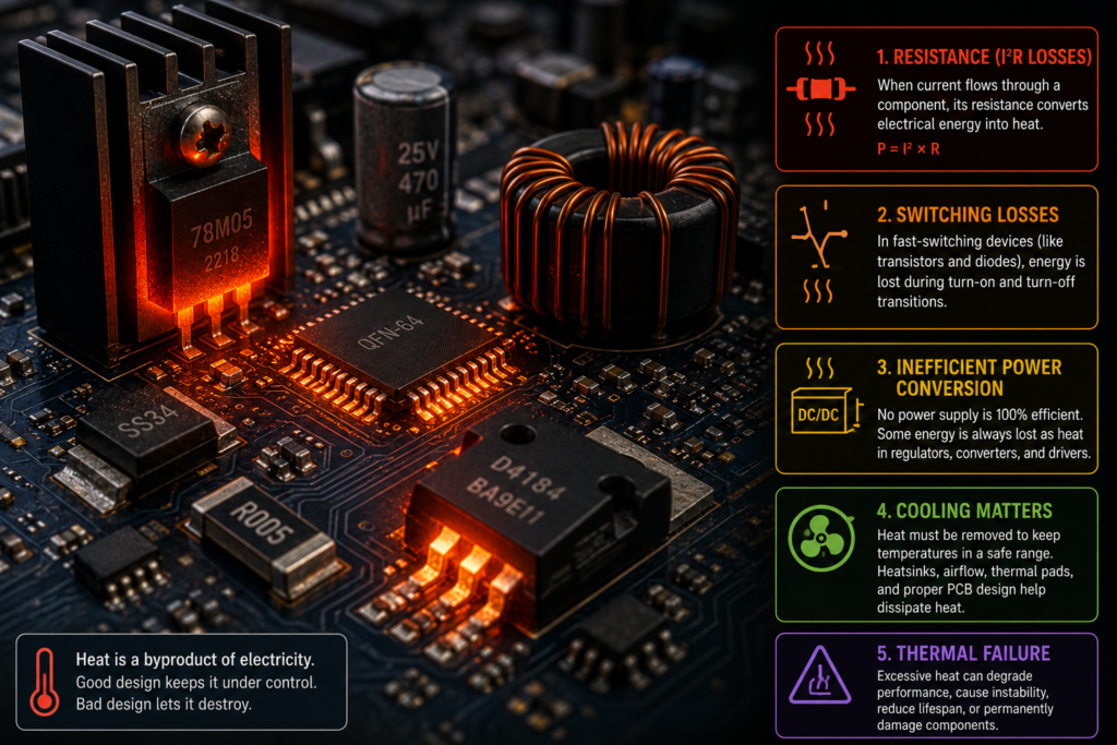
Touch the back of a laptop after a demanding game and you’ll feel it immediately. The charger is warm, the cooling fan is working overtime, and somewhere inside the case millions—actually billions—of microscopic electrical events are turning part of the incoming energy into heat.
That heat is not necessarily a sign that something is broken.
Electronic components warm up because real circuits are never perfectly efficient. Wires have resistance. Transistors do not switch instantaneously. Voltage converters lose a little energy during every conversion. Even capacitors, inductors and circuit-board tracks have imperfections that generate heat when current flows through them.
A modest temperature rise is normal.
Too much heat, though, shortens component life, changes electrical behaviour and may eventually cause permanent failure. That is why cooling is not an optional finishing touch in electronic design. In many products, it is part of the circuit’s survival plan.
Electrical Energy Has to Go Somewhere
Electronic equipment takes electrical energy from a battery, power supply or wall outlet and uses it to perform work.
A motor converts electrical energy into movement. An LED converts some of it into light. A speaker converts it into sound. A computer processor uses it to switch billions of transistors and process information.
But none of these conversions is perfect.
The energy that does not become useful output is commonly converted into heat.
For example, imagine a power converter receiving 100 watts and delivering 90 watts to its load. The missing 10 watts has not vanished. Most of it becomes heat inside switching transistors, inductors, diodes, capacitors and circuit-board conductors.
That may not sound like much. Ten watts is roughly the heat output of a small soldering iron spread across a compact enclosure. Without ventilation or a heatsink, temperatures can climb rather quickly.
Heat is often the receipt left behind by inefficiency.
Resistance Turns Current Into Heat
Every real conductor has some electrical resistance.
Copper wire has low resistance, but not zero. Circuit-board tracks have resistance. Connectors, switches, relay contacts and semiconductor junctions resist current as well.
When current flows through resistance, electrical energy is converted into heat. The power lost can be calculated using:
[
P = I^2R
]
Where:
- (P) is the heat-producing power loss in watts;
- (I) is the current in amperes;
- (R) is the resistance in ohms.
The important detail is that current is squared.
Double the current and the heating loss becomes four times greater. Triple the current and the loss becomes nine times greater.
This is why a connection that seems acceptable at a low current may become dangerously hot under a heavy load.
Suppose a connector has only 0.05 ohms of resistance.
At 2 amperes:
[
P = 2^2 \times 0.05 = 0.2\text{ W}
]
That produces a small amount of heat.
At 10 amperes:
[
P = 10^2 \times 0.05 = 5\text{ W}
]
Now the same tiny connection is producing 5 watts of heat in a concentrated area. Plastic may soften, contacts may oxidise, and resistance may rise further.
Then things begin feeding on themselves.
More resistance creates more heat. More heat damages the contact. The damaged contact develops even more resistance. Eventually, the connector discolours, melts or burns.
Not ideal.
Why Resistors Are Supposed to Get Warm
A resistor is specifically designed to oppose current and dissipate electrical energy.
In many circuits, producing heat is part of its job.
A resistor may limit LED current, divide voltage, discharge a capacitor, set transistor bias or absorb excess energy. The heat it generates is expected, provided the resistor remains within its rated power and temperature limits.
A resistor’s power can be calculated in several ways:
[
P = I^2R
]
[
P = \frac{V^2}{R}
]
[
P = VI
]
A resistor rated for 0.25 watts should not normally be expected to dissipate 0.25 watts continuously under every possible condition without becoming hot. Engineers usually include some margin and may use a larger power rating to reduce temperature and improve reliability.
A small resistor can become too hot to touch while still technically operating within its maximum specification. “Within specification” does not always mean “comfortable for human fingers.”
This catches beginners out surprisingly often.
Transistors Heat Up While Conducting
Power transistors are used as electronic switches or amplifying devices.
When fully off, an ideal transistor would block current and dissipate no power. When fully on, it would carry current with no voltage drop and again produce no heat.
Real transistors are less cooperative.
When a transistor is on, it still has some resistance or voltage drop. Current flowing through that imperfection produces conduction loss.
For a MOSFET, the conduction loss is often estimated using:
[
P_{conduction} = I^2R_{DS(on)}
]
Here, (R_{DS(on)}) is the MOSFET’s resistance while switched on.
A MOSFET with an on-resistance of 0.01 ohms carrying 20 amperes would lose approximately:
[
P = 20^2 \times 0.01
]
[
P = 4\text{ W}
]
Four watts concentrated inside a small semiconductor package is enough to produce a substantial temperature rise.
The on-resistance also tends to increase as the MOSFET gets hotter. That means conduction losses can rise with temperature, making thermal design even more important.
Other transistors, such as bipolar junction transistors and insulated-gate bipolar transistors, may be analysed using their voltage drop and current:
[
P = VI
]
No semiconductor behaves like a perfect switch. There is always a price for carrying current.
Usually, that price arrives as heat.
Switching Losses Happen During the Transition
A transistor in a switching power supply may turn on and off thousands, hundreds of thousands or even millions of times per second.
While fully off, current is low.
While fully on, voltage across the device is low.
But during the brief transition between those two states, the transistor may experience significant voltage and current at the same time. Since electrical power is voltage multiplied by current, each transition creates a small burst of heat.
One burst is tiny. Millions of bursts per second are not.
These are called switching losses.
Switching losses depend on factors such as:
- switching frequency;
- transistor turn-on and turn-off time;
- voltage;
- current;
- gate-drive strength;
- circuit layout;
- parasitic capacitance and inductance;
- diode recovery behaviour.
Increasing switching frequency can make a power converter smaller and improve its control response. However, it also creates more switching events every second.
There is always a trade-off.
Switch too slowly and the inductor, transformer or filter components may need to be larger. Switch too quickly and transistor losses, electromagnetic interference and circuit-layout problems become harder to control.
Electronic design has a habit of moving the difficulty rather than removing it.
Why Processors and Graphics Chips Become Hot
Modern processors contain enormous numbers of transistors switching at high speed.
Each transistor uses only a microscopic amount of energy per switching event. Add billions of transistors, high clock frequencies and repeated charging and discharging of internal capacitances, and the total power becomes significant.
That is why a processor may consume tens or hundreds of watts while physically occupying an area smaller than a postage stamp.
The heat is generated inside the silicon die. It must then travel through:
- the semiconductor junction;
- the chip package;
- the thermal interface material;
- the heatsink;
- the surrounding air or cooling liquid.
Every stage resists heat flow.
If heat cannot leave the chip as quickly as it is produced, the junction temperature rises. The processor may then reduce its clock speed and voltage to protect itself. This is known as thermal throttling.
Performance drops, but the chip survives.
Usually.
Power Conversion Is Never Perfect
Many electronic devices need voltages different from the available supply.
A laptop may receive 20 volts from its charger but require several lower voltages internally. A processor core may operate near 1 volt. Memory, fans, storage devices and communication circuits all need their own supply rails.
Voltage regulators perform these conversions.
There are two broad types commonly encountered:
- linear regulators;
- switching regulators.
Both can generate heat, but for different reasons.
Why Linear Regulators Get Hot
A linear regulator reduces voltage by effectively dropping the unwanted voltage across itself.
The power converted into heat is approximately:
[
P_{loss} = (V_{in}-V_{out})I
]
Suppose a linear regulator converts 12 volts to 5 volts while supplying 1 ampere.
The voltage drop is:
[
12-5=7\text{ V}
]
The regulator therefore dissipates:
[
P = 7\times1 = 7\text{ W}
]
Meanwhile, the load receives:
[
P_{load}=5\times1=5\text{ W}
]
The regulator is producing more heat than the useful power delivered to the load.
That is a terrible arrangement for efficiency, though linear regulators remain useful because they can be simple, inexpensive and electrically quiet.
At low currents or with a small voltage difference, the loss may be acceptable. At high currents, a heatsink may be required—or a switching converter may be the far better choice.
Why Switching Regulators Still Generate Heat
A switching regulator converts power more efficiently by rapidly switching current through inductors, transformers, capacitors and semiconductor devices.
Instead of continuously burning off the excess voltage, it transfers energy in controlled packets.
Efficiency may exceed 90%, and in well-designed systems it can be even higher. Still, it is never exactly 100%.
Losses occur in:
- transistor conduction;
- transistor switching;
- diode voltage drops;
- inductor winding resistance;
- magnetic core losses;
- capacitor equivalent series resistance;
- control circuitry;
- circuit-board tracks.
A converter delivering 100 watts at 90% efficiency draws about 111 watts from its source. The difference—roughly 11 watts—becomes heat.
At 97% efficiency, the same converter would lose only about 3 watts.
A few percentage points can make a dramatic thermal difference, especially in compact equipment.
That is why engineers can become strangely excited over a 1% efficiency improvement. It may sound tiny on paper, but inside a sealed enclosure it can mean the difference between pleasantly warm and repeatedly dead.
Capacitors Can Heat Up Too
Capacitors are often imagined as components that simply store charge without consuming energy.
Real capacitors have internal losses.
One important parameter is equivalent series resistance, usually shortened to ESR. It represents the small amount of effective resistance inside the capacitor.
When ripple current flows through the capacitor, ESR produces heat:
[
P = I_{ripple}^2 \times ESR
]
This is particularly important in switching power supplies, motor drives and audio amplifiers, where capacitors may handle substantial alternating current.
As electrolytic capacitors age, their ESR may increase. Higher ESR produces more heat, which accelerates ageing and may raise ESR further.
Eventually, the capacitor may bulge, leak electrolyte, lose capacitance or fail completely.
Heat is one of the main reasons electrolytic capacitors have limited lifespans.
A capacitor positioned next to a heatsink or power resistor may age far faster than the same component mounted in a cooler area. Circuit-board layout matters—not just electrically, but thermally.
Inductors and Transformers Also Produce Heat
Inductors and transformers contain copper windings and magnetic cores.
The windings have resistance, so current creates copper loss:
[
P_{copper}=I^2R
]
The magnetic core also experiences losses as its magnetic field changes. These include hysteresis losses and eddy-current losses.
Core heating depends on:
- switching frequency;
- magnetic flux density;
- core material;
- component shape;
- temperature;
- waveform.
A transformer can become warm even when it is not heavily loaded because its core experiences magnetising losses whenever voltage is applied.
Under heavy load, winding current increases and copper losses become more significant.
An overloaded transformer may become extremely hot, damage its insulation and eventually develop shorted turns. Once that begins, current rises further and failure can happen rather quickly.
Sometimes it smells before it fails.
That distinctive hot-varnish smell is not one to ignore.
Diodes Lose Energy Through Voltage Drop
A conducting diode has a voltage drop across it.
If a silicon diode has a forward voltage of 0.7 volts while carrying 5 amperes, its approximate power loss is:
[
P=0.7\times5
]
[
P=3.5\text{ W}
]
That heat must leave the diode somehow.
Schottky diodes often have a lower forward voltage and can reduce conduction losses. However, they may have higher leakage current, especially at high temperatures.
In switching circuits, diodes may also experience reverse-recovery losses. When the voltage reverses, the diode does not always stop conducting instantly. A brief reverse current can produce additional heating and stress.
This is one reason synchronous converters replace diodes with actively controlled MOSFETs in high-efficiency designs.
The circuit becomes more complicated, naturally. Better efficiency rarely arrives for free.
Poor Connections Create Local Hotspots
A whole circuit may appear to be carrying a reasonable current while one connector, solder joint or terminal becomes dangerously hot.
The cause is often elevated contact resistance.
Loose screws, corrosion, cracked solder joints and poorly crimped terminals reduce the effective contact area. Current is forced through a smaller or less reliable path, concentrating heat in one location.
Warning signs include:
- browned circuit boards;
- melted connector housings;
- discoloured terminals;
- intermittent operation;
- buzzing or crackling;
- a burnt-plastic smell;
- heat that appears only under load.
A thermal camera can reveal these hotspots before visible damage becomes obvious.
Oddly enough, the component that feels hottest may not be the original source of the problem. Heat can travel through copper tracks, metal terminals and nearby components.
Thermal troubleshooting takes a bit of detective work.
Why Small Components Can Become Extremely Hot
Heat generation is only half the story.
The other half is how easily that heat can escape.
A large component has more surface area from which to transfer heat into the air. A tiny semiconductor die may generate several watts in an extremely small volume.
That produces a high power density.
Ten watts spread across a large metal enclosure may barely be noticeable. Ten watts inside a small integrated circuit can destroy it within seconds unless the heat is transferred away efficiently.
This is why electronic components have thermal ratings, not just electrical ratings.
A transistor may be capable of carrying a certain current only when its case is held at a specified temperature. Without an adequate heatsink, its safe current may be much lower.
Datasheet numbers are often conditional.
The enormous current printed on the front page may assume perfect cooling, short pulses or a case temperature that your actual circuit will never achieve. The smaller notes and graphs usually tell the less glamorous truth.
How Heat Leaves an Electronic Component
Heat moves through three main mechanisms:
Conduction
Conduction transfers heat through solid materials.
Heat travels from a semiconductor die into its package, then through thermal paste or an insulating pad into a heatsink. Copper circuit-board areas can also conduct heat away from small components.
Thicker copper, thermal vias and large metal pads are often used to spread heat across a circuit board.
Convection
Convection transfers heat through moving air or liquid.
Warm air near a component rises and is replaced by cooler air. Fans accelerate this process by forcing more air across the hot surface.
Liquid-cooling systems transfer heat into a circulating fluid, which carries it to a radiator.
Radiation
Hot objects also release energy as electromagnetic radiation.
At normal electronic temperatures, radiation usually contributes less than conduction and convection, but it is still part of the overall heat-transfer process.
Cooling systems rarely rely on only one mechanism. A processor, for instance, conducts heat into a heatsink, which then transfers it to moving air through convection while also radiating a small amount into its surroundings.
What Does a Heatsink Actually Do?
A heatsink does not destroy heat.
It spreads heat over a larger surface area so that the surrounding air can carry it away more effectively.
The larger surface area reduces the temperature rise required to transfer a particular amount of heat.
Heatsinks often have fins because fins create far more surface area than a flat metal block of the same size.
Aluminium is commonly used because it conducts heat reasonably well, is lightweight and is relatively inexpensive. Copper conducts heat better but is heavier and generally costs more.
Some cooling systems combine a copper base with aluminium fins. Best of both worlds, more or less.
Why Thermal Paste Is Needed
A processor package and heatsink may appear smooth, but their surfaces contain microscopic gaps and irregularities.
If the surfaces are placed together without an interface material, those gaps trap air. Air is a poor conductor of heat.
Thermal paste fills the tiny imperfections and creates a better thermal path between the component and heatsink.
The goal is not to create a thick layer. Thermal paste itself is usually less conductive than metal. It should fill gaps, not become a sandwich filling.
Too little paste can leave air pockets. Too much may create an unnecessarily thick thermal barrier or make a mess around the socket.
More paste is not automatically more cooling.
Passive Cooling Versus Active Cooling
Passive cooling uses natural convection, conduction and radiation. It has no fans or pumps.
Examples include:
- heatsinks;
- metal enclosures;
- copper circuit-board areas;
- ventilation openings;
- heat spreaders.
Passive cooling is quiet, reliable and requires no moving parts. Its cooling capability, however, is limited by surface area and ambient temperature.
Active cooling uses powered devices such as:
- fans;
- blowers;
- pumps;
- thermoelectric coolers;
- refrigeration systems.
Active cooling can remove much more heat from a compact space, but fans wear out, collect dust and create noise. Pumps introduce additional failure points.
A cooling fan failing does not immediately stop the electronic circuit from producing heat. That is the uncomfortable part.
Thermal Resistance Explains Temperature Rise
Electronic thermal design often uses a concept called thermal resistance.
Thermal resistance describes how much the temperature rises for each watt of heat flowing through a path. It is usually expressed in degrees Celsius per watt.
A simple estimate is:
[
\Delta T=P\times R_{\theta}
]
Where:
- (\Delta T) is the temperature rise;
- (P) is dissipated power;
- (R_{\theta}) is thermal resistance.
Suppose a component dissipates 5 watts and has a junction-to-ambient thermal resistance of 20°C per watt.
Its junction temperature may rise approximately:
[
5\times20=100^\circ C
]
above ambient temperature.
If the surrounding air is already 30°C, the junction could reach around 130°C.
Add a suitable heatsink that reduces the total thermal resistance to 5°C per watt, and the rise becomes:
[
5\times5=25^\circ C
]
The same electrical loss now produces a far safer operating temperature.
This is why reducing thermal resistance can matter just as much as reducing electrical power loss.
Ambient Temperature Changes Everything
Cooling depends on the temperature difference between a component and its surroundings.
A heatsink works well when the surrounding air is cool. Place the same equipment inside a sealed cabinet under direct sunlight, and its cooling performance changes dramatically.
Industrial control panels are often affected by:
- high room temperature;
- sunlight;
- dust-clogged filters;
- failed cabinet fans;
- closely packed components;
- heat produced by neighbouring drives and power supplies.
A component that operates reliably in a 20°C laboratory may overheat inside a 45°C cabinet.
This is why component ratings are often derated at higher ambient temperatures.
The environment is part of the circuit, even though it does not appear on the schematic.
What Is Thermal Derating?
Derating means operating a component below its maximum advertised rating to improve reliability and account for real-world conditions.
A resistor rated for 1 watt may be used at only 0.5 watt. A transistor capable of 30 amperes under ideal conditions may be limited to much less in the actual product. A capacitor rated for 105°C may be kept below 80°C whenever possible.
Maximum ratings are limits, not recommended targets.
Driving every component at its maximum voltage, current and temperature may make the product cheaper or smaller, but it leaves little tolerance for:
- hot weather;
- manufacturing variation;
- blocked ventilation;
- ageing;
- temporary overloads;
- dust;
- voltage fluctuations.
Good design includes margin.
Otherwise, the product may work perfectly on the test bench and fail six months later in someone’s poorly ventilated cupboard.
What Happens When Electronics Overheat?
High temperature changes the electrical properties of components.
Resistance may increase. Semiconductor leakage current may rise. Capacitor life may fall. Insulation may soften or break down.
Possible symptoms include:
- reduced performance;
- unexpected resets;
- display glitches;
- distorted audio;
- unstable voltages;
- intermittent operation;
- thermal shutdown;
- shortened battery life;
- permanent component damage.
Processors and power electronics often include temperature sensors and protection circuits. When a limit is reached, the system may reduce power or switch off.
Older or simpler circuits may have no such protection.
They simply get hotter until something gives up.
Thermal Runaway Can Destroy Components
Thermal runaway occurs when rising temperature causes a component to dissipate even more power, which raises the temperature further.
The process reinforces itself.
For example, semiconductor leakage current often increases with temperature. More leakage produces additional heat. The extra heat creates still more leakage.
Certain transistor circuits can also draw more current as they warm unless properly stabilised.
Lithium-ion battery faults can produce a more dramatic form of thermal runaway, where internal heating causes chemical reactions that release additional heat. That subject deserves its own article, frankly.
Thermal runaway is dangerous because the temperature rise may accelerate rather than settle at a stable level.
Cooling and protective circuits must interrupt the cycle before damage becomes unavoidable.
Heat Causes Components to Age Faster
Electronic components may survive high temperature temporarily while still suffering long-term damage.
Chemical and material-degradation processes generally accelerate as temperature rises.
Electrolytic capacitors are especially sensitive. Their electrolyte gradually dries out, increasing ESR and reducing capacitance. A commonly used engineering rule suggests that capacitor life may approximately double for every 10°C reduction in operating temperature, although the exact relationship depends on the component.
Semiconductor bonding wires, solder joints, plastics and insulation also suffer from repeated heating and cooling.
These thermal cycles cause materials to expand and contract. Because different materials expand at different rates, mechanical stress builds over time.
Eventually, solder joints may crack, circuit boards may warp and connections may become intermittent.
The device works while cold. It fails when warm. Then it starts working again after cooling down.
A technician’s favourite sort of fault.
Dust Makes Cooling Worse
Dust does more than make electronics look neglected.
It forms an insulating layer over heatsinks and components, reducing heat transfer. It also blocks air passages and restricts fan airflow.
In computer systems, a dust-packed heatsink can cause higher fan speeds, thermal throttling and unexpected shutdowns. In industrial panels, blocked filters may raise the temperature of every device inside the cabinet.
Some dust is conductive or absorbs moisture, introducing additional electrical problems.
Cleaning cooling paths can restore performance, but compressed air should be used carefully. Fans should not be allowed to spin uncontrollably from a high-pressure air jet, and equipment must be properly isolated before maintenance.
Blowing dust deeper into the power supply is not quite the same thing as cleaning it.
Why Cooling Fans Get Louder Over Time
A fan may run faster because the electronics are producing more heat—or because cooling has become less effective.
Common causes include:
- dust buildup;
- dried thermal paste;
- obstructed air vents;
- warmer room temperature;
- background software load;
- worn fan bearings;
- failing components drawing excess current.
A louder fan is not always the problem itself. It may be responding correctly to another issue.
If a fan becomes noisy due to bearing wear, its speed may eventually fall or it may stop completely. The electronic device then loses a major part of its cooling system.
Noise is annoying. Silence, in that situation, may be worse.
Can Electronics Be Too Cold?
Most everyday electronic problems involve excessive heat, but very low temperatures can also cause trouble.
Cold conditions can change battery performance, capacitor characteristics, display behaviour and mechanical dimensions. Condensation may form when cold equipment is brought into a warm, humid room.
Still, within normal operating conditions, cooler electronics generally last longer than hotter ones.
The goal is not to freeze the circuit. It is to keep the component junctions comfortably below their maximum temperatures while avoiding moisture and extreme thermal stress.
How Engineers Reduce Heat
There are two broad approaches:
- produce less heat;
- remove heat more effectively.
Reducing heat may involve:
- selecting lower-resistance transistors;
- improving gate-drive circuits;
- reducing switching losses;
- using more efficient converter topologies;
- choosing lower-ESR capacitors;
- increasing conductor size;
- improving connector quality;
- lowering current;
- distributing loads across multiple components.
Removing heat may involve:
- heatsinks;
- fans;
- heat pipes;
- thermal pads;
- larger copper areas;
- ventilation;
- liquid cooling;
- metal enclosures;
- better component spacing.
The best thermal design usually combines both.
There is little sense in building an enormous cooling system around a circuit that wastes half its input power unnecessarily. Equally, even an efficient circuit may fail if its heat is trapped inside a sealed plastic box.
When Is Component Heat Normal?
Some components are expected to become warm or even quite hot during operation.
These commonly include:
- power resistors;
- processors;
- graphics chips;
- voltage regulators;
- transformers;
- power transistors;
- rectifier diodes;
- charging circuits;
- motor drives.
Whether the temperature is acceptable depends on the component’s specification, measured junction or case temperature, power level and surrounding conditions.
Touch is not a reliable measuring instrument.
A surface at 60°C feels very hot to a finger, but certain components may be designed to operate safely above that temperature. Conversely, the outside of a package may feel only warm while the internal semiconductor junction is much hotter.
Temperature sensors, thermocouples, thermal cameras and datasheet calculations provide more useful information.
Warning Signs of a Thermal Problem
Heat deserves investigation when you notice:
- repeated thermal shutdowns;
- a burning smell;
- browned circuit boards;
- melted plastic;
- bulging capacitors;
- unusually loud fans;
- unstable operation after warming up;
- equipment that works again after cooling;
- a component much hotter than identical nearby components;
- reduced output under load.
Disconnect equipment if there are signs of smoke, melting, sparking or severe overheating.
Do not cover ventilation openings or continue operating equipment that smells burnt. The product is not “settling in.” Something is being cooked.
Heat Is Usually a Symptom of Energy Loss
Electronic components get hot because some of the electrical energy passing through them is converted into heat.
Resistance creates (I^2R) losses. Transistors lose energy while conducting and switching. Voltage converters are never perfectly efficient. Capacitors, inductors, transformers, diodes and connectors all contribute their own smaller losses.
Cooling systems then move that heat away through conduction, convection and radiation.
When the heat produced equals the heat removed, the component reaches a stable temperature. When heat is produced faster than it can escape, temperature continues rising.
Eventually, performance drops, protection activates or something fails.
So warmth is not automatically bad. It is often just evidence that real electronics are doing real work.
Excessive heat is different.
That is the circuit telling you—sometimes rather bluntly—that energy is being lost faster than the design can handle it.