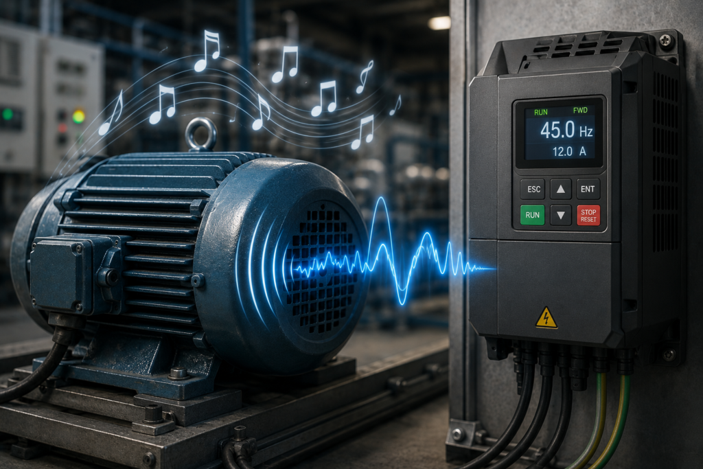
A motor connected directly to the mains usually produces a familiar low hum.
Connect the same motor to a variable-frequency drive, and suddenly it develops a musical career.
It may whistle at low speed, sing at one particular frequency, buzz under load or produce a sharp electronic tone that changes whenever a parameter is adjusted. Sometimes the noise is faint. Sometimes it can be heard across the workshop, cutting through fans, pumps and the usual industrial racket.
The motor is not necessarily failing.
A VFD controls motor speed by creating a rapidly switched output rather than delivering a perfectly smooth sine wave. Those electrical pulses produce changing magnetic forces inside the motor. The stator laminations, windings, motor frame and even the connected machine can vibrate in response.
When those vibrations fall inside the range of human hearing, the motor becomes audible.
The exact sound depends on the VFD’s switching frequency, pulse-width-modulation method, motor construction, operating speed, load and mechanical resonance. In many cases, changing the correct drive parameter can reduce the noise considerably.
There is a catch, naturally. Quieter operation may increase VFD heating or require output-current derating.
Nothing in drive engineering comes entirely free.
A VFD Does Not Produce a Perfect Sine Wave
A standard AC induction motor is designed to operate from an alternating voltage.
When connected directly to a three-phase supply, it receives three approximately sinusoidal voltages separated by 120 electrical degrees. Their combined effect creates a rotating magnetic field inside the stator.
A variable-frequency drive must reproduce that rotating field while also changing its frequency and voltage.
To do this, the VFD normally follows three broad stages:
- The incoming AC supply is rectified into DC.
- Capacitors smooth and store energy on the internal DC bus.
- Power transistors switch the DC voltage rapidly to create a controlled three-phase output.
The output voltage is not a smooth sine wave when viewed closely.
It consists of a sequence of high-speed voltage pulses switching between DC-bus levels. By changing the width and timing of those pulses, the drive controls the average voltage and current supplied to the motor.
The motor’s inductance smooths much of the resulting current, so the magnetic field behaves more like the sinusoidal waveform the motor needs.
Still, it is not perfect.
Small ripple currents and harmonic components remain, and those can create sound.
What Is Pulse-Width Modulation?
The switching method used by most modern VFDs is called pulse-width modulation, usually shortened to PWM.
The VFD’s output transistors switch fully on and fully off. Rather than operating halfway between those states, they produce pulses of different widths.
A series of narrow and wide pulses can create an average voltage that follows the shape of a sine wave.
When more output voltage is required, the drive keeps the transistor on for a greater portion of each switching cycle. When less voltage is required, the pulses become narrower.
The motor does not respond to each pulse as though it were a separate start command. Its inductance and magnetic structure average the pulses into a more continuous current.
Even so, each switching event produces a rapid change in voltage. Thousands of those changes happen every second.
That repeated electrical activity creates magnetic forces at the switching frequency and at related harmonic frequencies. If the motor’s structure responds mechanically, those forces become audible vibration.
Switching Frequency Is Often the Main Source of the Whistle
The VFD’s output transistors operate at a switching frequency, also called the carrier frequency.
Depending on the drive, this may be somewhere around a few kilohertz to well above 10 kilohertz. Exact available values vary by model, power rating and control method.
For example, a drive might switch at:
- 2 kHz;
- 4 kHz;
- 8 kHz;
- 12 kHz;
- 16 kHz.
A frequency of 4 kHz means the power transistors may perform approximately 4,000 switching cycles per second.
If the resulting motor vibration occurs near that frequency, a person may hear a 4 kHz tone. That can sound like a whistle, whine or high-pitched electrical squeal.
The sound may also contain sidebands and harmonics rather than one perfectly clean note. In practice, the motor can sound less like a tuning fork and more like a confused electronic insect.
The Carrier Frequency and Motor Speed Are Different Things
Two separate frequencies are involved, and they should not be confused.
The output or fundamental frequency controls the motor’s magnetic-field speed. In a basic induction-motor application, the VFD may vary this from nearly zero to 50 Hz, 60 Hz or higher.
The switching frequency controls how quickly the drive’s transistors produce the PWM pulses. This is usually measured in thousands of hertz.
For example, the drive could be operating the motor at:
- 30 Hz output frequency;
- 8 kHz switching frequency.
The 30 Hz value determines the approximate motor speed.
The 8 kHz activity helps construct the output waveform and may produce the audible whistle.
Changing motor speed therefore does not necessarily move the main switching tone by the same amount. However, the interaction between switching frequency, output frequency and motor harmonics can make the sound change as speed changes.
Why the Motor Vibrates
Electrical current flowing through the stator windings produces magnetic fields.
Those fields interact with the motor’s iron core and rotor. The interaction creates torque, which is the useful part, but it also produces small forces that repeatedly pull and push on the motor’s physical structure.
The stator core is built from many thin steel laminations. Windings sit inside slots around that core. None of these parts is infinitely rigid.
As the magnetic field changes:
- the laminations can expand and contract slightly;
- the windings can experience electromagnetic forces;
- the stator teeth can vibrate;
- the motor housing can flex;
- mounting feet can transmit vibration into the machine frame.
Individually, the movements are tiny.
Repeated thousands of times per second, though, they can generate a surprisingly clear sound.
Magnetostriction Contributes to Motor Noise
Ferromagnetic materials can change shape slightly when magnetised. This effect is called magnetostriction.
The dimensional change is extremely small, but the magnetic field in a motor is constantly changing. As a result, the steel core experiences repeated microscopic movement.
With a smooth sinusoidal supply, magnetostriction already contributes to the familiar motor hum.
A VFD introduces high-frequency voltage pulses and additional harmonic content. These can excite the steel laminations at frequencies that are far more noticeable to the human ear.
The motor may therefore produce both:
- a low-frequency magnetic hum related to the fundamental supply;
- a higher-frequency whistle related to PWM switching.
Sometimes the sounds overlap, and the result is a tone that seems to rise, flutter or change character with load.
Windings Can Move Slightly Too
The copper windings inside a motor carry changing currents and sit within strong magnetic fields.
Electromagnetic forces act on those conductors. If the windings are not held completely rigid by varnish, insulation and mechanical support, they may move by a tiny amount.
Loose or ageing windings can make VFD-related noise more noticeable.
This does not automatically mean the motor is about to fail, but an unusual increase in noise—especially when combined with overheating, vibration or insulation smell—deserves attention.
Two nominally identical motors can sound different on the same drive because their construction tolerances, winding impregnation and mechanical stiffness are not perfectly identical.
One whistles quietly.
The other performs as though it has been waiting years for a solo.
Mechanical Resonance Can Make One Frequency Much Louder
Every mechanical structure has natural frequencies at which it vibrates more easily.
This is called resonance.
The motor frame, fan cover, mounting plate, gearbox, pump casing and connected machine structure can all have their own resonant frequencies.
When an electrical force from the VFD matches one of those natural frequencies, the vibration can become much larger.
That is why a motor may sound acceptable at 32 Hz, become extremely loud at 36 Hz and then quieten again at 40 Hz.
The electrical excitation may be present across the entire speed range. It simply becomes much more audible when it lines up with a mechanical resonance.
The motor is not necessarily producing more total power loss at that exact point. The structure is just responding more enthusiastically.
A wine glass behaves similarly when exposed to the right tone, though hopefully the motor does not end the demonstration in the same way.
Why the Sound Changes With Motor Speed
Some noises remain at roughly the same pitch because they are tied mainly to a fixed switching frequency.
Other sounds change with speed because they are related to:
- fundamental electrical frequency;
- rotor speed;
- slip frequency;
- fan speed;
- bearing frequencies;
- mechanical resonance;
- load vibration;
- switching sidebands.
A useful rough observation is:
- A nearly constant high-pitched tone often points toward the carrier frequency.
- A tone that rises and falls with motor speed may involve the output frequency, mechanical components or switching sidebands.
- A noise appearing only in a narrow speed range may indicate resonance.
- Grinding, knocking or rumbling is less likely to be ordinary PWM noise and should prompt a mechanical inspection.
This is not a complete diagnostic method, but it helps separate a normal electronic whistle from a bearing that is having a much worse day.
Why Low Switching Frequencies Are More Audible
A lower carrier frequency is more likely to fall within the most sensitive part of human hearing.
For example, switching around 2–4 kHz can produce a very noticeable tone. Human hearing is particularly sensitive to sounds in part of this range, which is also one reason alarms and warning tones often live there.
Raising the switching frequency can move the most prominent tone higher.
At sufficiently high frequency, some adults may barely hear it or may not hear it at all. Younger people often hear higher frequencies more easily, so one technician may insist the motor is silent while another is standing nearby wondering how everyone else is tolerating the screaming.
Hearing sensitivity is annoyingly democratic like that.
Raising the Carrier Frequency Can Make the Motor Quieter
Many VFDs provide a parameter for changing the PWM carrier or switching frequency.
Increasing it can:
- move the switching tone above the most sensitive hearing range;
- reduce audible motor whine;
- reduce current ripple;
- make motor operation sound smoother;
- sometimes reduce certain low-frequency torque pulsations.
This is one of the first parameters people consider when trying to quiet a VFD-driven motor.
It can work very well.
However, the drive manufacturer’s manual must be checked before making the adjustment because a higher carrier frequency increases switching losses inside the VFD.
Why Higher Switching Frequency Heats the VFD
A power transistor loses relatively little energy when it is fully off and relatively little when it is fully on.
During the transition between those states, it briefly experiences significant voltage and current at the same time.
Every transition produces a small switching loss.
Raise the carrier frequency, and the transistors must make more transitions every second. The total switching loss rises.
This can cause:
- greater VFD heatsink temperature;
- increased cooling-fan operation;
- reduced maximum output current;
- required drive derating;
- earlier thermal trips in hot cabinets.
A VFD capable of supplying its full rated current at 4 kHz may require derating when operated at 12 or 16 kHz.
The exact limits vary significantly between manufacturers and drive sizes.
This is why changing the carrier-frequency parameter without reading the manual is not a harmless audio adjustment.
You may silence the motor while making the drive considerably less comfortable.
Higher Carrier Frequency Can Increase Cable-Related Stress
A VFD output cable has capacitance between conductors and from conductors to earth.
Every rapid voltage pulse charges and discharges that capacitance. More switching events per second mean more capacitive current.
With long motor cables, higher carrier frequency may contribute to:
- greater leakage current;
- increased VFD output current;
- heating;
- earth-fault or residual-current trips;
- electromagnetic interference;
- stress on output filters;
- motor-bearing current problems.
Long cables can also produce reflected-wave effects that increase the peak voltage reaching the motor terminals.
The relationship between carrier frequency, cable length, voltage rise time and motor insulation stress is not always simple. Still, a higher carrier setting is not automatically better merely because the workshop becomes quieter.
The cable and motor insulation must be suitable for inverter operation.
Lower Carrier Frequency Has Its Own Advantages
Reducing the switching frequency may:
- lower VFD switching losses;
- reduce drive temperature;
- allow greater output-current capacity;
- improve reliability in hot environments;
- reduce cable-charging current;
- help certain long-cable applications.
This is why larger drives often use lower default carrier frequencies than small drives.
A 0.75 kW VFD may switch relatively quietly without much difficulty. A drive controlling a very large motor handles far more current, so each transistor transition involves more energy. High-frequency switching becomes thermally expensive.
Large industrial drives are not usually designed around the comfort of someone standing beside the motor listening for a faint whistle.
They are designed to survive.
PWM Creates More Than One Audible Frequency
The motor sound is not always equal to the carrier frequency alone.
PWM produces a spectrum containing:
- the fundamental motor frequency;
- switching-frequency components;
- harmonics of the switching frequency;
- sidebands around the carrier;
- combinations of carrier and output frequency.
These components can excite different mechanical parts of the motor.
As the VFD changes output frequency, the sidebands shift. That can make the audible tone rise, fall, pulse or appear to wobble even when the carrier-frequency parameter itself remains fixed.
This explains why a motor may seem to “sing” rather than produce one steady note.
The drive is generating an organised pattern of pulses. The motor translates some of that pattern into sound.
Not intentionally, but impressively.
Random PWM Can Make the Tone Less Annoying
Some VFDs include a random carrier, random PWM or spread-spectrum function.
Instead of switching at one perfectly fixed frequency, the drive varies the carrier slightly within a controlled range.
The total acoustic energy may not disappear, but it is spread across a wider band of frequencies. A sharp whistle becomes a softer hiss or less distinct whine.
Human hearing often finds a broad, low-level sound less irritating than a single narrow tone.
This feature may be listed under names such as:
- random PWM;
- carrier-frequency modulation;
- acoustic-noise reduction;
- spread-spectrum switching;
- random carrier.
Availability depends on the drive model.
As always, the manual wins. Inventing a parameter because another brand had one is rarely productive.
Automatic Carrier-Frequency Control
Some drives adjust their switching frequency automatically.
The VFD may use a higher carrier at light load for quieter operation, then reduce it when:
- output current rises;
- internal temperature increases;
- motor speed falls;
- overload conditions appear;
- cooling becomes insufficient.
This allows the system to balance sound and thermal performance.
An operator may notice that the motor suddenly becomes louder during heavy load or hot weather. The drive may not be developing a fault. It may simply be reducing the carrier frequency to protect its power stage.
Checking diagnostic data and parameter settings can confirm this behaviour.
Motor Control Mode Can Affect the Sound
VFDs may offer several motor-control methods, including:
- basic volts-per-hertz control;
- sensorless vector control;
- closed-loop vector control;
- permanent-magnet motor control;
- specialised energy-saving modes.
These modes calculate voltage and current differently.
Poorly matched motor data or an incorrect control mode can produce excessive current ripple, torque pulsation or unstable operation. The motor may buzz, growl or sound rough at low speed.
Performing the manufacturer’s recommended motor identification or autotune procedure can improve control.
The VFD may need accurate values for:
- motor rated voltage;
- motor rated current;
- rated frequency;
- rated speed;
- rated power;
- power factor;
- winding resistance.
Typing “close enough” values into a vector-control drive can produce close-enough results, which is not always a compliment.
Incorrect Motor Data Can Increase Noise
If the VFD does not know the correct motor characteristics, its internal model may calculate the wrong voltage, slip compensation or magnetic flux.
Possible effects include:
- rough low-speed operation;
- excessive current;
- unstable torque;
- motor overheating;
- audible humming;
- vibration;
- poor starting performance.
The motor nameplate should be entered carefully.
A drive configured for a 400V, 50 Hz motor should not be casually connected to a differently rated motor without adjusting the parameters.
This is especially important when using vector control, where the drive relies more heavily on its motor model.
Voltage Boost Can Make a Motor Hum More
At low speed, the resistance of the motor windings becomes more significant compared with the reduced output voltage.
Some VFDs apply low-frequency voltage boost to maintain magnetic flux and starting torque.
Too little boost may result in weak torque.
Too much boost can over-magnetise the motor, causing:
- high current;
- increased heating;
- magnetic saturation;
- stronger vibration;
- louder humming.
Older or basic drives may require manual boost adjustment. Modern vector drives often calculate it automatically.
Increasing voltage boost because “the motor sounds stronger” is not a reliable tuning method.
Sometimes louder is simply hotter.
Certain Speeds Can Be Skipped
If the motor or machine resonates strongly at a particular operating frequency, many VFDs allow the designer to define skip frequencies or prohibited speed bands.
For example, if severe vibration occurs around 37 Hz, the drive can be configured to avoid continuous operation in a narrow range around that point.
During acceleration or deceleration, the VFD passes through the range but does not remain there.
This can help with:
- fan resonance;
- pump vibration;
- duct resonance;
- frame vibration;
- coupling resonance;
- audible mechanical tones.
Skip frequencies should not be used to hide an actual mechanical defect.
A cracked mounting foot still deserves repair, even if the drive can be programmed to avoid the frequency where it rattles loudest.
Acceleration and Deceleration Can Affect Temporary Sounds
A motor may pass through several resonant frequencies while speeding up or slowing down.
With a long acceleration time, it remains in each region longer, so a whistle or vibration may be more noticeable.
A shorter ramp can move through troublesome frequencies more quickly, provided the motor, load and VFD can handle the required torque and current.
Changing acceleration time may therefore alter the sound without changing the carrier frequency.
However, excessively short acceleration can cause:
- overcurrent trips;
- mechanical stress;
- belt slip;
- coupling damage;
- process instability.
Likewise, aggressive deceleration can raise the DC-bus voltage and cause overvoltage trips unless braking energy is handled correctly.
Noise reduction is not the only consideration.
Motor Cooling Becomes Worse at Low Speed
A standard totally enclosed fan-cooled motor often uses a cooling fan mounted on its shaft.
When the motor slows down, the fan slows down too.
The VFD may still ask the motor to produce substantial torque, which means significant current and heat, but the motor receives less airflow.
This is separate from the audible whistle, yet it matters during parameter changes. A motor that sounds quieter at low speed may still be overheating quietly.
For continuous high-torque operation at low speed, the application may require:
- a separately powered cooling fan;
- a larger motor;
- thermal sensors;
- reduced torque;
- an inverter-duty motor.
Do not use sound as a temperature indicator.
A motor can fail with almost professional silence.
Is the Noise Coming From the Motor or the VFD?
Both can produce audible sound.
The motor may whistle because of magnetic forces and mechanical vibration.
The VFD itself may also make noise from:
- cooling fans;
- DC-link components;
- internal inductors;
- electromagnetic filters;
- contactors;
- transformer-like magnetic components.
An input or output reactor can hum. A braking resistor may make nearby metalwork expand and tick. Cabinet panels can resonate and amplify what began as a small internal vibration.
Standing close to each part of the system may help locate the source, but keep appropriate distance from live equipment.
A mechanic’s stethoscope or vibration measurement equipment can be useful when applied safely by trained personnel.
Placing an ear against an energised cabinet is not a measurement procedure.
When a Whistle Is Probably Normal
A steady high-pitched tone is often normal when:
- it appeared after the motor was connected to a VFD;
- the motor operates smoothly;
- current remains within expected limits;
- temperatures are normal;
- no unusual mechanical vibration is present;
- the tone changes after adjusting the carrier frequency;
- there are no drive fault codes.
Some motor and VFD combinations are simply more audible than others.
The sound may be annoying without indicating damage.
Still, baseline behaviour matters. A motor that has always produced a mild whistle is different from one that suddenly develops a harsh new sound after years of quiet operation.
When the Sound Should Be Investigated
Further inspection is sensible when the noise is accompanied by:
- excessive motor current;
- overheating;
- burning smell;
- severe vibration;
- bearing noise;
- unstable speed;
- torque loss;
- VFD overcurrent trips;
- earth-fault trips;
- insulation alarms;
- loose mounting hardware;
- sudden changes in sound;
- arcing or crackling.
A mechanical rumble, scraping sound or repeated knocking should not be dismissed as PWM noise.
The VFD can make diagnosis more confusing because it introduces tones that were not present during direct-on-line operation. That does not mean every new sound comes from switching frequency.
Bearings still fail. Fans still rub. Bolts still come loose.
The electronics have not eliminated ordinary machinery problems. They have merely added a soundtrack.
Practical Parameter Adjustments
If the motor is operating correctly but the audible noise is unacceptable, several adjustments may help.
Increase the carrier frequency
This often moves the main tone to a higher, less audible range.
Before changing it:
- check the VFD manual;
- review output-current derating;
- confirm cabinet cooling;
- consider motor-cable length;
- monitor drive temperature;
- verify motor insulation suitability.
Enable random PWM
Where available, random PWM can spread the tone over a wider frequency range and make it less noticeable.
Use automatic carrier adjustment
Some drives can optimise the switching frequency according to current and temperature.
Verify motor nameplate parameters
Incorrect motor data can cause rough or noisy control.
Perform motor autotuning
Follow the manufacturer’s procedure. Some autotunes require the motor to rotate, while others are stationary.
Check the control mode
A suitable vector-control mode may improve low-speed smoothness, though it must be configured correctly.
Review voltage boost
Excessive low-frequency boost can increase current, hum and heating.
Configure skip frequencies
Use them when a specific speed excites genuine mechanical resonance.
Inspect mounting and driven equipment
Tighten loose hardware and check couplings, guards, fan covers, bearings and frames.
Consider an output reactor or sine-wave filter
In certain applications, output filtering can smooth the waveform and reduce motor noise, cable stress and voltage peaks.
Filter selection must match the VFD, motor, switching frequency and cable system.
Output Reactors and Filters
A VFD output reactor adds inductance between the drive and motor.
It can reduce current ripple, limit the rate of current change and help with certain long-cable or motor-noise problems.
A dV/dt filter is designed primarily to reduce the rate of voltage rise and peak voltage at the motor terminals.
A sine-wave filter provides much stronger filtering and can make the motor voltage more closely resemble a sinusoidal waveform.
A sine-wave filter may significantly reduce audible motor noise, but it adds:
- cost;
- size;
- heat;
- voltage drop;
- installation requirements;
- frequency limitations.
The filter must be approved for the drive application.
Connecting random capacitors to a VFD output in an attempt to smooth the waveform can damage the drive. VFD outputs and ordinary power-factor-correction capacitors do not make friendly neighbours.
Inverter-Duty Motors May Behave Better
Motors intended for inverter operation may include features such as:
- improved winding insulation;
- better resistance to voltage pulses;
- suitable cooling arrangements;
- reinforced winding support;
- bearing-current mitigation;
- thermal sensors;
- wider operating-speed ranges.
An inverter-duty motor is not guaranteed to be silent, but it is designed with VFD operation in mind.
Older motors may operate successfully from a VFD, especially at moderate cable lengths and voltages. However, insulation condition, bearing design, cooling and operating range should be considered.
A motor manufactured long before modern fast-switching drives became common did not have the opportunity to object during the design meeting.
Never Ignore the VFD Manual
Carrier-frequency limits and derating rules vary considerably.
One drive may permit 16 kHz operation at full current. Another may require substantial derating above 4 kHz. A large drive may allow only a narrow range.
The manual may also specify:
- maximum motor-cable length;
- required output reactors;
- compatible filter types;
- motor-insulation requirements;
- permissible leakage current;
- grounding methods;
- protected frequency ranges;
- limitations by control mode.
These details matter more than general internet advice.
The correct parameter is not merely the one that makes the motor quieter. It is the one that keeps the complete system within its electrical and thermal limits.
Safety Before Adjusting or Inspecting
VFD systems can retain dangerous voltage after incoming power is disconnected.
The internal DC-bus capacitors need time to discharge. The display going dark does not prove that the bus is safe.
Before working on the motor, drive or wiring:
- isolate all energy sources;
- follow lockout and tagout procedures;
- wait for the manufacturer’s specified discharge time;
- verify absence of voltage using suitable test equipment;
- remember that the motor may be driven by stored mechanical energy;
- follow site and manufacturer safety procedures.
Parameter adjustments should also be made carefully. A change to control mode, maximum frequency, torque boost or motor data can affect machine movement.
A quieter motor is not worth an unexpected start.
Why the Motor Sings
A VFD makes an electric motor whistle or sing because it controls the motor using high-speed PWM voltage pulses.
Those pulses create changing magnetic forces inside the stator. The steel laminations, windings, frame and connected machinery respond with tiny physical movements. When the resulting vibration falls within the audible range—or excites a mechanical resonance—you hear it as a whistle, buzz or electronic tone.
The carrier frequency often has the greatest influence on the high-pitched noise. Raising it can make the motor quieter, but it also increases switching losses and heat inside the VFD. Lowering it improves drive efficiency and thermal capacity, though the motor may become more audible.
Other adjustments, including random PWM, motor autotuning, control-mode selection, voltage boost and skip frequencies, can help in the right application.
The sound is often normal.
It is the motor physically responding to a power waveform made from thousands of precisely timed electrical pulses.
In other words, it is not really singing.
But standing beside one at 4 kHz for an entire shift, the distinction starts to feel rather academic.