The electrician presses Forward.
The contactor pulls in, the motor starts—and the conveyor runs backwards.
Nothing inside the motor has been mechanically flipped. The windings have not moved. The gearbox is still exactly where it was five minutes ago.
Only two supply wires were exchanged.
So, why does swapping two phases reverse a motor?
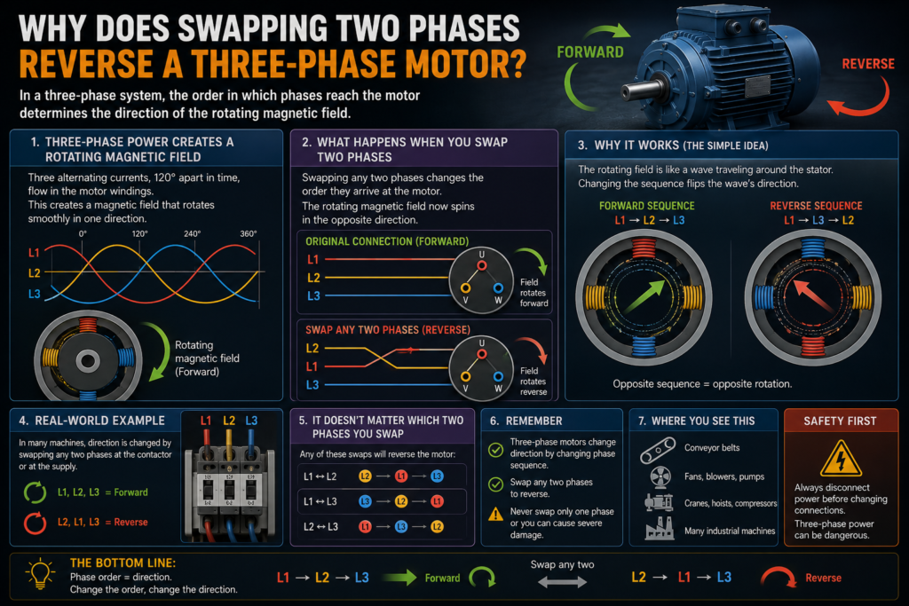
A three-phase motor turns because the three supply phases create a rotating magnetic field inside the stator. The direction of that field depends on the order in which the phase voltages reach their peaks.
Swap any two phases and the phase sequence reverses.
The magnetic field begins rotating in the opposite direction, and the motor follows it.
Simple electrically. Potentially rather dramatic mechanically.
What Is Phase Sequence?
A three-phase supply contains three alternating voltages separated from one another by 120 electrical degrees.
The phases are commonly identified as:
L1
L2
L3
Or:
Phase A
Phase B
Phase C
They do not all reach their positive peak at the same moment.
Instead, they rise and fall in a repeating order. One possible sequence is:
L1 → L2 → L3After L3, the cycle starts again:
L1 → L2 → L3 → L1 → L2 → L3This order is known as the phase sequence, phase rotation or phase order.
A phase-sequence monitoring relay can detect whether the incoming phases appear in the expected order. Siemens, for example, offers monitoring relays specifically designed to recognize phase sequence and phase failure in three-phase systems.
How Three Phases Create a Rotating Magnetic Field
A typical three-phase motor has three groups of stator windings positioned around the motor.
Each winding is supplied from a different phase.
Because the three currents reach their peaks at different times, the magnetic fields produced by the windings also rise and fall in sequence.
The combined result is not a magnetic field that merely switches on and off.
It rotates around the stator.
A simplified view might look like this:
Time 1: Magnetic field points toward winding L1

Time 2: Magnetic field moves toward winding L2

Time 3: Magnetic field moves toward winding L3

Time 4: The pattern repeats
Siemens describes a three-phase supply as producing a rotating magnetic field in the motor stator. Its motor documentation also links a defined U-V-W phase sequence and clockwise rotating field to a corresponding clockwise rotor direction.
This rotating field is what determines the motor’s direction.
How an Induction Motor Follows the Field
In a squirrel-cage induction motor, the rotor is not normally supplied through external electrical wires.
The rotating stator field cuts through the rotor conductors and induces current in them.
Those rotor currents create their own magnetic field. The interaction between the rotor field and stator field produces torque.
The rotor accelerates in the same general direction as the rotating stator field.
It never quite reaches the field’s synchronous speed during normal motoring operation because some speed difference—called slip—is needed to induce rotor current and produce torque.
The important point is straightforward:
Stator field rotates clockwise
↓
Rotor turns clockwise
Reverse the stator field:
Stator field rotates counterclockwise
↓
Rotor turns counterclockwise
The rotor does not decide which direction looks more productive.
It follows the field.
What Changes When Two Phases Are Swapped?
Suppose the original phase sequence is:
L1 → L2 → L3Now exchange L2 and L3:
L1 → L3 → L2The order has reversed.
As a result, the magnetic field moves around the stator in the opposite direction.
The motor follows and its shaft rotation reverses.
Schneider Electric’s motor-drive guidance confirms that reversing two of the three motor leads changes the output phase rotation and corrects a motor that is running in the wrong direction.
You could swap:
- L1 and L2
- L2 and L3
- L1 and L3
Any one of those exchanges reverses the phase sequence.
Only two conductors need to move.
Why Swapping All Three Phases Does Not Necessarily Reverse It
Moving every phase one position while keeping the same cyclic order does not reverse rotation.
These three arrangements have the same sequence direction:
L1 → L2 → L3
L2 → L3 → L1
L3 → L1 → L2
The starting label has changed, but the order still progresses in the same direction.
These arrangements form the opposite sequence:
L1 → L3 → L2
L3 → L2 → L1
L2 → L1 → L3
So the motor does not care which terminal was called “first” in a written list.
It cares about the order in which the three waveforms arrive.
Does This Work With Every Three-Phase Motor?
Swapping two phases reverses the rotation of many common three-phase motors, including:
- Squirrel-cage induction motors
- Wound-rotor induction motors
- Many three-phase synchronous motors
- Certain permanent-magnet motors when operated with suitable controls
However, the exact procedure depends on how the motor is supplied.
A motor connected directly to the mains behaves differently from a motor controlled by a variable-frequency drive, servo drive or electronic motor starter.
Always follow the motor and controller manufacturer’s instructions.
A three-phase motor is reversible in principle.
The machinery attached to it may have much stronger opinions.
What Is a Forward and Reverse Contactor Circuit?
A reversing starter commonly uses two three-pole contactors:
K1 = Forward contactor

K2 = Reverse contactor
The forward contactor connects the phases to the motor in the normal sequence:
Supply        Motor

L1 ───────── U
L2 ───────── V
L3 ───────── W
The reverse contactor crosses two phases:
Supply        Motor

L1 ───────── W
L2 ───────── V
L3 ───────── U
The exact two phases selected for crossing are not important as long as the resulting sequence is reversed.
One contactor supplies:
L1 → U
L2 → V
L3 → W
The other might supply:
L1 → W
L2 → V
L3 → U
Since two motor connections have changed places, the rotating magnetic field reverses.
ABB describes compact reversing contactor assemblies as paired contactors with mechanical interlocking for controlling three-phase motor loads in opposite directions.
Why Both Contactors Must Never Close Together
Look closely at the reversing connections.
The two contactors wire two phases differently. If both close at the same time, the crossed connections can join one supply phase directly to another.
That creates a phase-to-phase short circuit.
Possible consequences include:
- Extremely high fault current
- An electrical arc
- Welded contactor contacts
- Damaged busbars
- Blown fuses
- Tripped breakers
- Burned wiring
- Arc-flash injury
- Fire
- Damage to the motor-control panel
ABB warns that switching reversing contactors too quickly can create a phase-to-phase short circuit, particularly if the first contactor’s arc has not been extinguished before the second contactor closes.
A reversing starter therefore needs more than two contactors and an optimistic push-button arrangement.
It needs interlocking.
What Is Electrical Interlocking?
Electrical interlocking uses auxiliary contacts to prevent both contactor coils from being energized together.
A normally closed auxiliary contact from the reverse contactor is placed in the forward contactor’s coil circuit.
Likewise, a normally closed auxiliary contact from the forward contactor is placed in the reverse coil circuit.
Simplified:
Forward coil circuit includes a normally closed K2 contact.

Reverse coil circuit includes a normally closed K1 contact.
When K1 is energized, its auxiliary contact opens the K2 coil circuit.
When K2 is energized, its auxiliary contact opens the K1 coil circuit.
The logic becomes:
K1 ON → K2 cannot energize

K2 ON → K1 cannot energize
This arrangement is often combined with push-button or PLC logic that requires the running contactor to drop out before the opposite direction can be selected.
Electrical interlocking is important.
It should not be the only barrier.
What Is Mechanical Interlocking?
A mechanical interlock physically links the two contactors.
When one contactor is closed, the mechanism blocks the other contactor from closing.
ABB describes its mechanical interlock as a device that prevents one contactor from closing while the other remains closed. Its reversing-contactor guidance also requires mutual electrical interlocking in addition to mechanical protection.
Mechanical interlocking protects against situations such as:
- Welded auxiliary contacts
- Incorrect PLC outputs
- Control-wiring faults
- Both push buttons being pressed
- A failed output relay
- Software errors
- Contactor timing differences
A good reversing circuit normally uses both:
Electrical interlocking
+
Mechanical interlocking
One prevents the command.
The other prevents the physical movement.
Belts and braces. In this case, entirely justified.
Why A PLC Program Alone Is Not Enough
A PLC can be programmed so the forward and reverse outputs are never energized simultaneously.
That is useful, but software should not be the only protection against a phase-to-phase short circuit.
PLC logic can fail because of:
- Incorrect program changes
- Forced outputs
- Output-module faults
- Wiring errors
- Duplicate coil logic
- Communication problems
- Maintenance bypasses
- Commissioning mistakes
The hardwired electrical and mechanical interlocks remain effective even when the software does something unexpected.
The PLC may be clever.
Copper and plastic should still have the final veto.
Why a Delay May Be Needed Before Reversing
A motor has inertia.
When the forward contactor opens, the shaft does not stop instantly. It continues turning because the rotor and driven machinery still contain mechanical energy.
If the reverse contactor closes immediately, the motor’s rotating field suddenly opposes the existing rotor movement.
This is known as plugging or counter-current braking.
It can produce:
- Very high current
- Strong mechanical torque
- Violent shock loading
- Contact wear
- Coupling damage
- Gearbox stress
- Belt damage
- Tripped protection
- Overheating
Some systems are specifically designed for controlled plugging.
Others are not.
A normal reversing starter may use a time delay, zero-speed switch, encoder feedback or drive control to ensure the motor has slowed sufficiently before the opposite direction is allowed.
The required method depends on:
- Motor size
- Load inertia
- Required stopping time
- Number of reversals
- Mechanical design
- Contactor rating
- Braking system
- Manufacturer instructions
A small unloaded motor may stop quickly.
A large fan or loaded conveyor may keep turning for quite a while, as if hoping nobody noticed the stop command.
Reversing With a Variable-Frequency Drive
A motor controlled by a variable-frequency drive needs slightly different thinking.
Most VFDs rectify the incoming AC supply into an internal DC bus. The inverter stage then creates a new three-phase output for the motor.
Because of this, swapping two phases on the input side of many VFDs does not change the motor direction.
The drive creates its own output phase sequence.
Schneider Electric explains that a VFD rectifies the incoming supply to a DC bus and then uses its inverter stage to produce the motor’s three-phase output. Its guidance states that changing the input phase order will not normally alter output rotation.
To reverse a VFD-driven motor, the usual options are:
- Issue a reverse-run command
- Change the drive’s direction parameter
- Swap two motor leads on the VFD output
The exact method must follow the drive manufacturer’s instructions.
Do not place ordinary contactors between a running VFD and motor unless the drive system has been specifically designed for output-side switching.
Why Swapping VFD Output Leads Works
The VFD supplies the motor through output terminals commonly identified as:
U/T1
V/T2
W/T3
If the motor runs backwards during a forward command, swapping any two output leads changes the phase order reaching the motor.
Schneider specifically recommends exchanging two leads on the drive output when the motor’s physical direction does not match the commanded direction.
However, first confirm that the problem is genuinely motor phasing.
A machine may also run in the wrong direction because:
- The reverse command is active
- Digital inputs are assigned incorrectly
- PLC logic is inverted
- The direction parameter was changed
- Encoder feedback polarity is wrong
- Mechanical transmission reverses the shaft direction
- A bypass circuit has different phase order
Changing motor leads without checking the command may correct one operating mode while making another wrong.
Industrial machinery does enjoy keeping a spare fault ready.
What About a VFD Bypass Circuit?
Some installations allow a motor to run either through a VFD or directly from the mains using a bypass contactor arrangement.
The motor direction must be checked in both modes.
If the motor turns correctly through the drive but incorrectly in bypass, the phase sequence differs between the two supply paths.
If it turns incorrectly in both modes, the wiring may need to be changed at a point common to both paths.
Schneider advises checking bypass rotation before changing motor leads because moving two conductors in the wrong location may correct VFD operation while reversing the bypass mode—or vice versa.
Bypass systems also require carefully designed contactor interlocking so the VFD output cannot be connected directly to the mains supply.
That particular mistake tends to be memorable.
How To Check Motor Direction Safely
Motor direction should be verified during commissioning and after work involving:
- Incoming supply cables
- Motor replacement
- Contactor replacement
- VFD replacement
- Motor-lead reconnection
- Generator changeover systems
- Transformer replacement
- Distribution-board modifications
Where the machinery design and safety procedures permit it, technicians often perform a brief controlled jog or bump test.
Before doing so:
- Confirm the area is clear.
- Verify guards and protective devices.
- Check that reverse movement cannot create a hazard.
- Disconnect the driven load where required.
- Confirm valves and process conditions.
- Warn nearby personnel.
- Be ready to stop the motor immediately.
- Observe the manufacturer’s defined viewing direction.
Motor direction descriptions such as clockwise and counterclockwise depend on which shaft end is being viewed. Siemens documentation, for example, defines rotation from a specified motor end rather than leaving the viewing direction to interpretation.
“Clockwise from where?” is not a pointless question.
It may be the only useful question in the room.
Using a Phase-Sequence Meter
A phase-sequence meter can identify the order of a three-phase supply without starting the motor.
Depending on the instrument, it may indicate:
- Clockwise sequence
- Counterclockwise sequence
- Correct phase order
- Reversed phase order
- Missing phase
This is useful when checking:
- Incoming utility supplies
- Generator connections
- Temporary power systems
- Industrial sockets
- Replacement panels
- Mobile machines
- Motor-control centres
A monitoring relay can also prevent startup when the incoming sequence is wrong. Schneider’s phase-reversal protection identifies incorrect phase sequence because it can cause motors and other rotating equipment to run opposite to the expected direction.
Still, the final machine direction should be confirmed mechanically.
The gearbox, belt arrangement or driven mechanism may reverse the relationship between motor-shaft direction and machine movement.
When Reverse Rotation Is Harmless
Some loads can operate in either direction when they are specifically designed for it.
Examples may include:
- Reversible conveyors
- Winches with proper controls
- Machine-tool feeds
- Positioning systems
- Reversing rolling equipment
- Certain mixers
- Doors and gates
- Traversing mechanisms
These machines still require suitable:
- Limit switches
- End-position protection
- Braking
- Interlocking
- Mechanical stops
- Control logic
- Overload protection
A motor’s ability to rotate backwards does not prove the machine can reverse without preparation.
The motor may be perfectly cheerful while the rest of the mechanism is having a dreadful afternoon.
When Reverse Rotation Can Damage a Pump
Many centrifugal pumps can rotate backwards briefly without immediate catastrophic failure, but they may produce very little useful flow or pressure.
Longer reverse operation can cause serious problems depending on the design.
Possible effects include:
- Reduced or absent flow
- Poor cooling
- Incorrect lubrication
- Abnormal axial loading
- Excessive vibration
- Loosening of direction-sensitive components
- Damage to the pump or motor assembly
Grundfos advises checking rotation whenever a three-phase pump connection is changed and warns that long-term reverse operation can severely damage the pump and motor assembly.
Never assume a pump is operating correctly because the motor sounds normal.
Check:
- Rotation arrow
- Discharge pressure
- Flow
- Motor current
- Vibration
- Manufacturer instructions
A backwards pump can sound surprisingly professional while accomplishing almost nothing.
Fans and Blowers
A fan rotating backwards may still move some air.
Usually, it moves much less than intended.
Possible consequences include:
- Poor cooling
- Reduced extraction
- Overheated equipment
- Incorrect airflow through filters
- Process-temperature problems
- Reduced motor cooling
- Unexpected noise and vibration
A motor’s own cooling fan may also be designed for one preferred direction.
If the main machine depends on forced ventilation, reverse rotation can allow motors, drives or process equipment to overheat even though the shaft appears to be spinning smoothly.
Motion alone is not proof of correct operation.
A desk fan waved backwards still moves air. It just does it with the confidence of someone reading the instructions upside down.
Conveyors and Material-Handling Equipment
Unexpected conveyor reversal can:
- Drop material
- Cause product collisions
- Jam transfer points
- Pull material into the wrong machine
- Release objects from an incline
- Overload a backstop
- Endanger workers
- Damage scrapers or tensioning systems
Inclined conveyors, bucket elevators and lifting mechanisms may include backstops or one-way devices that are not intended to absorb driven reverse torque.
Before bump-testing the motor, consider where the load will move.
“Only for one second” can be a surprisingly long time when gravity joins in.
Compressors and Refrigeration Equipment
Direction-sensitive compressors may rely on correct rotation for:
- Lubrication
- Oil circulation
- Cooling
- Compression
- Internal sealing
- Correct loading and unloading
Reverse rotation can result in little or no compression and may damage internal parts, depending on the compressor design.
Some equipment includes phase-sequence protection specifically to prevent the motor from starting with incorrect rotation.
Never repeatedly start a compressor in the wrong direction while troubleshooting.
The absence of immediate noise does not mean the lubrication system agrees with the experiment.
Hoists, Lifts and Positioning Machinery
On a hoist, crane or lifting mechanism, incorrect rotation can send the load in the opposite direction from the operator’s command.
Pressing Up could lower the load.
Pressing Close could open a clamp.
Pressing Forward could send a carriage towards the wrong end stop.
This can cause:
- Collision
- Dropped loads
- Overtravel
- Rope or chain problems
- Limit-switch bypass
- Crushing hazards
- Structural damage
Directional controls must therefore be function-tested under controlled conditions before normal operation.
Do not discover phase reversal with a suspended production load.
There are cheaper ways to make commissioning memorable.
Screw Conveyors and Threaded Mechanisms
A screw conveyor rotating backwards transports material in the opposite direction.
That may:
- Empty material into the wrong hopper
- Pack material against a closed end
- Overload the screw
- Block an inlet
- Damage seals
- Jam the process
Threaded shafts, impellers, nuts and couplings may also rely on a particular rotation direction to remain tight.
Whether reverse rotation can loosen them depends entirely on the mechanical design.
The motor does not know which fastener was expected to stay attached.
Lubrication and Cooling Systems
The driven machine may contain small auxiliary pumps or fans connected to the same shaft.
If rotation is wrong:
- Oil may not circulate correctly.
- Cooling airflow may reverse.
- Bearings may run without lubrication.
- Gearboxes may receive inadequate oil distribution.
- Seals may operate under incorrect pressure.
Damage may develop before the main machine shows an obvious problem.
This is why direction must be confirmed before extended running—not after an hour of observing that the shaft definitely turns.
What Happens If the Utility Phase Sequence Changes?
A utility supply, temporary generator or replacement transformer may introduce a different phase sequence after electrical work.
Every direct-on-line three-phase motor connected downstream could then attempt to run in the opposite direction.
That is especially dangerous at facilities containing:
- Pumps
- Compressors
- Refrigeration equipment
- Conveyors
- Hoists
- Fans
- Process machinery
Phase-sequence protection is often used where reverse rotation could create equipment damage or a safety hazard.
Siemens phase-sequence relays and Schneider motor-protection devices are designed to detect this condition before or immediately after startup, depending on the device and configuration.
After major supply work, checking one convenient motor and assuming the rest must be fine is not always enough.
Every critical direction-sensitive load should be included in the commissioning plan.
Does Swapping Two Phases Change Motor Speed?
Not under normal direct-on-line operation.
It changes the direction of the rotating magnetic field, but not its synchronous-speed magnitude.
Motor synchronous speed still depends mainly on:
Supply frequency
and
Number of motor poles
For example, a four-pole motor supplied at 50 Hz has a synchronous field speed of 1,500 rpm in either direction.
Swapping two phases changes:
+1,500 rpm directionto:
−1,500 rpm directionConceptually, at least.
The motor’s actual loaded speed remains slightly below synchronous speed for an induction motor, regardless of direction.
The gearbox and load may behave differently in reverse, but the electrical phase swap itself does not select a new speed.
Does Swapping Two Phases Change Voltage?
No.
If the supply is healthy, the phase-to-phase voltage remains the same.
You have changed the sequence, not the voltage magnitude.
For example:
Before swapping:
L1–L2 = 400 V
L2–L3 = 400 V
L3–L1 = 400 V
After swapping two phases, the same nominal line-to-line voltages remain available.
This is why an ordinary multimeter cannot determine phase sequence using only three separate voltage-magnitude readings.
All three phase-to-phase readings may look perfectly normal while the motor direction is completely wrong.
You need a phase-sequence instrument—or a controlled rotation test—to identify the order.
Common Phase-Reversal Myths
“You must reverse all three motor wires”
No.
Swapping any two phase conductors reverses the sequence.
“The motor changes direction because current flows backwards”
That is an oversimplification.
Each phase already alternates direction. The motor reverses because the order of the three phase waveforms changes, reversing the rotating magnetic field.
“Reversing the phases changes motor speed”
Not by itself.
It reverses direction while the synchronous-speed magnitude remains determined by frequency and pole count.
“Both reversing contactors can briefly overlap”
No.
Their crossed phase connections can create a phase-to-phase short circuit.
“PLC interlocking is enough”
Software interlocking is helpful, but hardwired electrical and mechanical interlocking provide essential additional protection.
“Swapping two phases before a VFD reverses the motor”
Usually not.
Most VFDs rectify the incoming AC and independently create their output phase sequence.
“If the motor can reverse, the machine can too”
Not necessarily.
Pumps, compressors, conveyors, fans, hoists and lubrication systems may be direction-sensitive.
“A backwards pump will simply pump backwards”
Often it will mainly produce poor pressure and flow rather than functioning as a useful reverse pump. Depending on its design, continued reverse operation may cause damage.
A Practical Reversing-Starter Checklist
Before commissioning a forward-and-reverse motor circuit, verify:
- The motor nameplate and connection are correct.
- The supply voltage and phase sequence are correct.
- Only two phases are crossed in the reverse path.
- Forward and reverse contactors have electrical interlocking.
- A mechanical interlock is installed.
- Both contactors cannot close together.
- Overload protection applies in both directions.
- A suitable transition delay is provided where required.
- Emergency-stop and safety circuits work in both directions.
- End limits are correctly assigned.
- The PLC command matches the contactor output.
- Forward and reverse labels match real machine movement.
- VFD and bypass directions match, where applicable.
- The driven machine can safely tolerate the test.
- Rotation is checked from the manufacturer’s specified viewing end.
Do not finalize the panel merely because both contactors make satisfying clicking sounds.
The machine’s definition of forward is the one that matters.
The Practical Answer
So, why does swapping two phases reverse a motor?
Because three-phase current creates a rotating magnetic field inside the motor.
With a phase sequence such as:
L1 → L2 → L3the magnetic field rotates in one direction.
Swap any two phases:
L1 → L3 → L2and the sequence reverses. The magnetic field rotates the other way, so the motor develops torque in the opposite direction.
A reversing starter automates this process using two contactors:
- The forward contactor supplies the normal phase sequence.
- The reverse contactor crosses two phases.
Those contactors must have electrical and mechanical interlocking because simultaneous closure can create a destructive phase-to-phase short circuit.
Most ordinary three-phase motors can rotate in either direction.
The real question is whether the connected machinery can.
Pumps may lose flow or suffer damage. Fans may stop cooling. Conveyors may dump material. Compressors may lose lubrication. Hoists may move opposite to the operator’s command.
The phase swap takes seconds.
Checking what the machine will do afterwards deserves considerably longer.